This pre start-u - Armstrong Pumps
This pre start-u - Armstrong Pumps
This pre start-u - Armstrong Pumps
- No tags were found...

You also want an ePaper? Increase the reach of your titles
YUMPU automatically turns print PDFs into web optimized ePapers that Google loves.
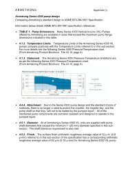
®FILE NO.:USF43.192DATE: July 30, 2000SUPERSEDES: NEWDATE:NEWHORIZONTAL SPLIT CASE AND END SUCTION TYPE DIESEL ENGINE DRIVEN FIRE PUMPPRE START-UP CHECKLIST (U.S. VERSION)<strong>This</strong> <strong>pre</strong> <strong>start</strong>-up checklist shows items that must be completed prior to a scheduled <strong>start</strong>-up. If the answer to anyquestions is “No”(when it should be “Yes”), is left blank or contradicts the requirements of NFPA 20, the installation is notready for <strong>start</strong>-up. Indicate “N/A” for not applicable wherever appropriate. These questions should be answered inconjunction with the fire pump (mechanical) contractor and electrical contractor. Check list must be returned signed anddated below.Fire Pump IO&M manuals are available on the <strong>Armstrong</strong>’s website www.armstrongpumps.comPlease note the attached “CLARKE Exhaust Pipe Data Fax” sheet (C13 158) is an integral part of properly completing thischecklist, specifically in confirming the exhaust piping has been properly sized. <strong>This</strong> can also be done by using thewww.clarkefire.com website to obtain immediate confirmation.The attached “ENGINE INSTALLATION CHECKLIST” must also to be completed by the installing contractor andsubmitted along with the other forms to the local <strong>Armstrong</strong> Darling Re<strong>pre</strong>sentative prior to scheduling <strong>start</strong>-up inspection.The sole purpose of this <strong>pre</strong> <strong>start</strong>-up checklist is to serve as a guide only. <strong>Armstrong</strong> does not assume any liability orresponsibility for the accuracy of this list or any items omitted. <strong>This</strong> list does not absolve the installing contractors of theirresponsibilities for proper installation in accordance with the local and national codes and standards.Project Name: _____________________________________________________________________________________Site Address: _____________________________________, City: ____________________, State: _________________Insuring Authority: __________________________________________________________________________________Flow Test to be performed by: Company Name: __________________________________________________________Contact: _________________________________ Tel: ________________________ Fax: ________________________Pre Start-Up Check Date: ____________________________________________________________________________Pre Start-Up Checklist completed by: a).Company Name: __________________________________________________b). Contact Name: ___________________________________________________c). Telephone: __________________________ Fax: _______________________I. NAMEPLATE DATA (must be taken directly from each equipment nameplate):1. Pump Model Number: ___________________________________________ Pump S/N: ______________________2. Rated Flow: _______________________ Rated Pressure: ______________ Pump Speed: ________________ rpm3. Controller Mfg: ______________________ Model Number: _______________________________________________4. Controller S/N: ______________________ Voltage: _____________________ Phase: ___________ Hz: __________5. Engine Mfg: _________________________ Engine Model Number: ________________________________________6. Engine S/N: ___________________________ Horsepower: ______________ Engine Speed: ________________ rpm7. Voltage: ___________________________ Phase: ______________________ Hz: ____________________________8. Jockey Pump Model Number: _______________________________________ Jockey Pump S/N: _______________9. Jockey Pump Motor Mfg: ___________________________________________ Model Number: __________________10. Jockey Pump Motor S/N: ____________ Horsepower: __________________ Motor Speed: ________________ rpm11. Jockey Pump Motor Voltage: __________ Phase: ______________________ Hz: ___________________________II. GENERAL INSTALLATION: YES NO1. Visual Inspection done of the overall pump assembly(No visible sign of cracks, damage, rust or watermarks). ____ ____2. All mechanical installation in accordance with NFPA 20 Standards. ____ ____3. All electrical installation in accordance with NFPA 70 Standards. ____ ____4. All electrical supplies correspond to all engine, motor and controller nameplates. ____ ____5. Entire pump assembly base securely anchored with foundation bolts of suitable size embedded inthe concrete floor. ____ ____6. Entire pump assembly base grouted sufficiently substantial to absorb any vibrationand to form a rigid support for the base plate. ____ ____7. Entire pump assembly base level and aligned with all connecting piping and fixtures. ____ ____8. Fire Pump System manual c/w certified performance curve and wiring diagrams available for <strong>start</strong>-up. ____ ____Page 1 of 6
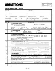
III. MAIN FIRE PUMP INSTALLATION – DIESEL ENGINE DRIVEN (HSC & ES):1. Pump installed in the proper direction of flow in relation to the system (Suction & Discharge Orientation). ____ ____2. Drive to Pump Assembly direction of rotation correct. ____ ____3. Pump to drive coupling re-aligned after the entire pump assembly base installation completedand coupling lubricated (usually shipped dry). ____ ____5. Minimum of 4 to 6 pipe diameters length of straight pipe installed at pump suction connection. ____ ____6. Suction and Discharge system piping supports c/w anchors installed near to but independent of thepump assembly. ____ ____7. System piping does not exert any strain on the pump casing. ____ ____8. Eccentric reducer installed on the pump suction side (as required by NFPA 20). ____ ____9. Concentric Increaser installed on the pump discharge side (as required by NFPA 20). ____ ____10. Suction line has been tested to ensure there aren’t any leaks. ____ ____11. Listed OS&Y Gate Valve installed close to pump on the suction sided of the pump. ____ ____12. Listed OS&Y Gate Valve or Butterfly Valve on pump discharge line. ____ ____13. A Listed Check Valve is installed and is in the proper direction. ____ ____IV. DIESEL ENGINE WITH HEAT EXCHANGER COOLING:1. Engine Crankcase (lube oil) level verified full (as per manufacturers specifications-Note JDFP engines mustonly use John Deere Engine Break-In Oil #TY22041 during the 1-year break-in period, see page 23 IO&M). ____ ____2. Engine cooling system filled with coolant conditioner/anti-freeze ASTM-4985 Grade. ____ ____3. Engine Block heater is connected. ____ ____4. Batteries are rack supported above floor, secured against displacement and located to avoidexcessive temperature, vibration, mechanical injury or flooding with water (NFPA 20 8-2.5.2.5 & 8-2.5.2.6). ____ ____5. Batteries filled, charged and connected to engine <strong>start</strong>ers. ____ ____6. Battery chargers are wired correctly (typically #10 AWG 0-25’, and #8 AWG 25-50’ linear feetfrom controller to engine block). ____ ____7. Battery cables as per engine manufacturer’s requirements (NFPA 20 8-2.5.2.5). ____ ____8. Heat Exchanger Main cooling line taken-off from the pump discharge line and prior to discharge check valve. ___ ____9. Heat Exchanger Main cooling line consists of an indicating manual shut-off valve, an approved flushingtype strainer, a <strong>pre</strong>ssure regulator (NFPA 20 8-2.6.3.2), an automatic valve (solenoid valve) listed for fireprotection service (NFPA 20 8-2.6.3.3), a second indicating manual shutoff valve and a <strong>pre</strong>ssure gaugeinstalled on the engine side of the last manual valve, all in accordance with NFPA 20 8-2.6.3.1.____ ____10. Heat Exchanger Water Supply Bypass line consists of manual valves, a flush-type strainer and a<strong>pre</strong>ssure regulator, installed around the main cooling line’s manual shut-off, strainer, <strong>pre</strong>ssure regulatorand automatic valve (NFPA 20 8-2.6.4). ____ ____11. Cooling water automatic valve (solenoid) wired correctly to the “W” terminal on the engine instrument panel. ____ ____12. Cooling water inlet & outlet connections properly installed on engine heat exchanger (NFPA 20 8-2.6.3). ____ ____13. Cooling loop strainers flushed clean (after installation). ____ ____14. Cooling loop waste outlet piped to drain. ____ ____15. Heat Exchanger Waste Outlet discharges into a visible waste cone (NFPA 20 8-2.6.5). ____ ____16. Exhaust system properly sized (see CLARKE Exhaust Pipe Data Fax sheet, complete and fax toCLARKE or go to www.clarkefire.com website, if other than CLARKE, contact manufacturer directly). ____ ____17. Exhaust system is independent, properly constructed, routed, supported, located and connected to enginein accordance with NFPA 20 8-5, including insulation, 9” away from combustible materials, etc.____ ____18. Exhaust pipe is same size diameter or larger than engine exhaust outlet (NFPA 20 8-5.3). ____ ____19. Residential silencer installed. ____ ____20. Fuel Tank Capacity in accordance with NFPA 20 8-4.3. ____ ____21. Fuel Supply Location in accordance with NFPA 20 8-4.5. ____ ____22. Fuel lines (both supply & return) connected to fuel tank and engine.23. Guard or protecting pipe on all exposed fuel lines (NFPA 20 8-4.2). ____ ____24. Flame-resistant flexible hoses listed for fire service at the engine for connection to fuel system piping. ____ ____25. Fuel tank drained of water and sediment. ____ ____26. Fuel tank filled with clean #2 diesel fuel (NFPA 20 8-4.7). ____ ____27. Is there a Fuel Solenoid Valve installed? If yes, can it be manually by-passed (NFPA 20 8-4.8). ____ ____28. Engine jacket water heater voltage connected to matching supply voltage (AC power) (only after coolantlevel verified as full).____ ____29. Air inlet filter installed on engine. ____ ____30. Fresh air supply, adequate for engine combustion and room ventilation (NFPA20 8-3.2 to 8-3.2.2 & FigureA-8-3.2(a)). ____ ____31. Room temperature controlled for a maximum 120 degrees F at the combustion air cleaner inlet withengine running at rated load (NFPA 20 8-3.2(1)). ____ ____Page 2 of 6
V. JOCKEY PUMP INSTALLATION:1. Jockey pump inlet and outlet are in the proper location. ____ ____2. Jockey pump direction of rotation is correct. ____ ____3. Jockey pump suction line is piped ahead of the main fire pump suction OS&Y Gate Valve. ____ ____4. Jockey pump discharge line is piped after the main fire pump discharge valve (OS&Y or Butterfly). ____ ____5. Jockey Line contains 2 isolation gate valves and a check valve. ____ ____VI. PUMP MINIMUM FITINGS:1. A 1/2” Automatic Air Release valve is installed on top of pump casing (applicable to HSC pumps only). ____ ____2. Compound Suction gauge with 3 ½” dial face with <strong>pre</strong>ssure range twice the maximum suction <strong>pre</strong>ssurebut not less than 100 psi) with ¼” gauge valve (as per NFPA 20 2-5.2). ____ ____3. Discharge gauge with 3 ½” dial face with <strong>pre</strong>ssure range twice the rated working pump <strong>pre</strong>ssure but notless than 200 psi) with ¼” gauge valve (NFPA 20 2-5.1). ____ ____VII. SENSING LINES FOR MAIN FIRE PUMP & JOCKEY PUMP:1. Main fire pump and Jockey pump sensing lines totally independent of each other and connected totheir respective controllers in accordance with NFPA 20 9-5.2.1. & (a), Figures A-7-5.2.1 (a) & (b). ____ ____2. Each sensing line is ½” non-ferrous metallic piping. ____ ____3. Each sensing line is complete with 2 bronze check valves, each with a 3/32” diameter hole drilled inthe flapper, orientated to open in the direction of the pump, and spaced 5 feet from each other as perNFPA 20 9-5.2.1 (b).____ ____VIII. DIESEL FIRE PUMP AND JOCKEY PUMP CONTROLLERS:1. Fire Pump Controller is located within sight of the engine (as per NFPA 20 9-2.1). ____ ____2. Fire Pump Controller installed not less than 12 inches above the floor (as per NFPA 20 9-2.2). ____ ____3. The appropriate incoming power service is connected and installed as per NFPA 20 and 70. ____ ____4. Battery chargers are wired correctly (typically #10 AWG 0-25’, and #8 AWG 25-50’ linear feetfrom controller to block on engine). ____ ____5. Proper materials used (including Liquid-tite conduit, etc.). ____ ____6. Listed termination kits used. ____ ____7. Main Fire Pump controller equipped with an automatic weekly exercise cycle ____ ____8. Fuses available and installed prior to <strong>start</strong>-up date (Jockey Pump Panel). ____ ____9. Separate manual and wiring diagram inside each controller enclosure. ____ ____10.Pressure Switch Rating verified. ____ ____11.Control Wiring, #14 AWG minimum used. ____ ____12. Controller terminals 1 to 12 wiring corresponds to engine terminals. ____ ____13. Electrical rating labels on controller, battery chargers compatible with incoming AC line, battery voltageand grounding polarity. Supply voltage to Diesel Controller is within 10% of controller nameplate. ____ ____IX. MAIN RELIEF VALVE (if applicable):1. Listed Main Relief Valve installed. ____ ____2. Located between the pump discharge and the check valve. ____ ____3. Confirm: Maximum Suction Pressure ___________ , Pump Shut-Off Pressure ___________System Rated Pressure ___________X. ENCLOSED DISCHARGE CONE (if applicable):1. Enclosed discharge cone installed on the outlet line of the main relief valve. ____ ____2. Provides for a visual indication of water movement or has a sight glass. ____ ____3. Piped to the drain, or discharges back to the main fire pump suction line. ____ ____XI. FLOW METER (if applicable):1. Listed for fire pump service and installed in proper direction. ____ ____2. Flow meter gauge display has a range of at least 1.75 times the rated flow of the fire pump. ____ ____3. Capable of being isolated and removed without affecting fire pump service. ____ ____4. Straight pipe length before and after flow meter in accordance with manufacturer's specifications. ____ ____Page 3 of 6
XII. BY-PASS LINE (if applicable):1. Pump by-pass line installed across the main fire pump. ____ ____2. Complete with listed check valve and isolation valves. ____ ____XIII. TEST FITTINGS (if applicable):1. Test tee installed after the check valve and before the discharge butterfly valve. ____ ____2. Hose valve header sized and contains the right number of hose valve outlets according toNFPA 20 Table 2-20____ ____3. Ball drip valve installed prior to the hose valve header (NFPA 20 2-14.3.3). ____ ____4. Indicating gate valve or Indicating butterfly valve installed between Test-Tee and Hose Valve Header. ____ ____XIV. LOW SUCTION PRESSURE SHUT-OFF PANEL (if applicable):1. Low Suction Pressure Shut-Off panel installed. ____ ____2. Sensing line and electrical connections installed in accordance with manufacturer’s instructions. ____ ____XV. ADDITIONAL COMMENTS:________________________________________________________________________________________________________________________________________________________________________________________________________Signed: ________________________________________________ Date: ________________________________________I certify the above items are completed and were checked at the job site and the pump equipment is ready for a <strong>start</strong>-upand performance test.Once fully completed, please return the above Pre Start-Up Checklist to __________________________________________(local U.S. <strong>Armstrong</strong> Darling Re<strong>pre</strong>sentative) to the attention of ________________________________________________<strong>start</strong>-up date(s) will be determined based on the availability of these parties. It is the responsibility of the installingcontractor to arrange for the other required parties to be <strong>pre</strong>sent and have the installation ready on the scheduled date ofthe <strong>start</strong>-up. Scheduling of fire pump <strong>start</strong>-up will commence only once the installation is deemed ready for <strong>start</strong>-up asderived from the answers provided on this form.Important: A standard <strong>start</strong>-up is based on a maximum 3 hours at the job site. Should the time required to complete the<strong>start</strong>-up exceed this standard duration or should the <strong>start</strong>-up service need to be repeated due to circumstances caused byother parties, and or situations out of our control, any additional service or incurred costs are the sole responsibility of theinstalling contractor.Before performing any tests, to avoid false alarms where a supervisory service is provided, the alarm receiving facilitiesmust always be notified by the building owner or designated re<strong>pre</strong>sentative.Prior to the Start-Up, the Installing Contractor must ensure that the Pre-Start-Up Verification has been performed andprovide confirmation to the local U.S. <strong>Armstrong</strong> Darling re<strong>pre</strong>sentative ensuring:1. Pump Alignment.2. Pump Packing Gland Adjusted.3. System Integrity.4. Electrical Integrity.5. All applicable items on the Pre Start-Up Checklist have been verified and answered accordingly.6. The installation is ready for <strong>start</strong>-up (including all air bled from the system and ready to flow water) and is inaccordance with all applicable national and local codes and standards.7. All applicable documentation is on-hand at <strong>start</strong>-up (including pump certified performance curve(s), equipmentmanuals & wiring diagrams)8. All the appropriate parties (e.g. AHJ-Fire Marshall, Electrician, Millwright/Pipe Fitter, Building Owner/Re<strong>pre</strong>sentative,etc.) will be <strong>pre</strong>sent throughout the entire <strong>start</strong>-up.S.A. <strong>Armstrong</strong> Limited23 Bertrand AvenueToronto, OntarioCanada, M1L 2P3Tel: (416) 755-2291Fax: (416) 759-9101Visit us at www.armstrongpumps.com<strong>Armstrong</strong> <strong>Pumps</strong> LimitedPeartree Road, StanwayColchester, EssexUnited Kingdom, C03 5JXTel: 01206-579491Fax: 01206-760532© S.A. <strong>Armstrong</strong> Limited 2000Page 4 of 6<strong>Armstrong</strong> <strong>Pumps</strong> Inc.93 East AvenueBuffalo, New YorkU.S.A. 14120-6594Tel: (716) 693-8813Fax: (716) 693-8970<strong>Armstrong</strong> Darling Inc.2200 Place TranscanadienneMontreal, QuebecCanada, H9P 2X5Tel: (514) 421-2424Fax: (514) 421-2436
CLARKEExhaust Pipe Data FaxTHIS FORM TO BE USED AS A MASTER FOR COPYING AND RETURNED TO YOUR MANUAL FOR FUTURE USEATTN: Sales Engineering DATE: __________________________FAX: 1-513-771-8930 SENT BY: __________________________PHONE: 1-513-771-2200 Company: __________________________FAX:__________________________INSTALLATION DATA: PHONE: ___________________________COMPANY/FACILITYADDRESSCITY/STATE/POSTAL CODECOUNTRYENGINE S/N & M/N:ENGINE RATED RPM:TYPE EXHAUST SYSTEM:__________________________________________________________________________________________________________________________SINGLE SILENCER ____________________ Check oneDUAL SILENCER ________________________EXHAUST PIPE SIZE:_________________ ________(SPECIFY DESIRED DIAMETER)EXHAUST PIPE LENGTH: ________________(SPECIFY TOTAL FEET, HORIZ & VERT)EXHAUST PIPE 45º ELBOW(S): _____________ _____________(SPECIFY QUANTITY IN EACH PIPE)EXHAUST PIPE 90º ELBOW(S): ____________ (SPECIFY QUANTITY IN EACH PIPE)EXHAUST PIPE ‘Y’ CONNECTION: _____________________(YES/NO)COMPLETE ALL BLANKS ABOVE THE DOUBLE LINEExhaust Pipe RecommendationMAXIMUM ALLOWED BACKPRESSURE: ________________________________________________________________________________H20 TOTAL SYSTEMRECOMMENDED PIPE SIZE: _____________________=_______________________ H2O BACKPRESSUREMAX ALLOWED SILENCER BACKPRESSURE: ________________________________________________________ H20 (SEE NOTE BELOW)COMMENTS:__________________________________________________________________________________________________________________________________________________________________________________________________________________NOTE: SILENCER BACKPRESSURE MUST BE ADDED TO PIPE BACKPRESSURE TO GET TOTAL SYSTEM BACKPRESSURE. THESILENCER MANUFACTURER MUST ADVISE SILENCER BACKPRESSURE.Page 5 of 6
ENGINE INSTALLATION CHECKLISTC13 158TO BE COMPLETED BY THE INSTALLING CONTRACTOR THEN SUBMITTED TO CLARKE SERVICE DEALERBY ARMSTRONG DARLING FIRE PUMP SERVICE DEPARTMENT PRIOR TO SCHEDULING START-UP INSPECTIONSection I:Project & Equipment Data• Facility Identification (Name) ___________________________________________________________________Address: ____________________________________________________________________________________State/Province _______________________________________________ Postal Zone __________ Country _____________________________Contact Name ______________________________________ __________ Phone _____________________________________ Fax ___________________________________________________________________________________• Pump Mfg. ______________________ Pump Model ____________________________Pump S/N ______________________________________________________________________Pump Rating _____________ (gpm/lpm); Pressure _______(psi/kpa); Speed _________________________ (rpm)• Controller Mfg. ______________________________________________Model ________________________________________ ; S/N ____________________________________________________________________________________• Engine Model _______________________________________________ S/N _____________________________________________ Speed (rpm) _________________________Section II:Sequential Checklist for Installing Contractor**Initial DateA. Engine-Pump alignment check; Service coupling/shaft as required. ____ ____B. Unit properly mounted & secured; Base grouted. ____ ____C. Controller wiring connected to engine junction box. ____ ____D. Batteries serviced and charged 24 hours; connected to engine. ____ ____E. Cooling water connections properly installed on engine heat exchanger,Both inlet and outlet; Confirm cooling water by-pass solenoid operation. ____ ____F. Exhaust system properly sized, routed and connected to engine. ____ ____G. Cooling system filled to proper level with <strong>pre</strong>mixed solution of water andcoolant conditioner (see engine manual for details). ____ ____H. Add engine oil to proper level (see engine manual for oil type & quantity). ____ ____I. Fuel lines (both supply and return) connected to fuel tank and engine. ____ ____J. Fuel tank filled with clean #2 diesel fuel; drain water & sediment from tank. ____ ____K. Engine jacket water heater connected to correct AC power (after item G). ____ ____L. Air inlet filter installed on engine; Fresh air supply adequate for enginecombustion and room ventilation. ____ ____**These items are to be completed before Installation Review and Start-up InspectionSubmitted by: ___________________________________________ Date: ________________________________Company: _____________________ City: ______________C 13272Page 6 of 6