On the aerodynamic optimization of mini-RPV ... - CAFE Foundation
On the aerodynamic optimization of mini-RPV ... - CAFE Foundation
On the aerodynamic optimization of mini-RPV ... - CAFE Foundation

Create successful ePaper yourself
Turn your PDF publications into a flip-book with our unique Google optimized e-Paper software.
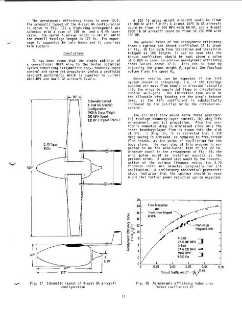
The <strong>aerodynamic</strong> efficiency index is over 12.0.The schematic layout <strong>of</strong> <strong>the</strong> 4-seat GA configurationis shown in Fig. 17; a high-wing arrangement wasselected with a span <strong>of</strong> 360 in. and a 0.45 taperratio. The useful fuselage length i s 147 in. while<strong>the</strong> overall fuselaoe lenoth i s 174 in. The emDennageis supported -by twin booms and it comprisestwin rudders.ConclusionsIt has been shown that <strong>the</strong> simole addition <strong>of</strong>a conventional NACA wing to <strong>the</strong> tested optimizedsystem comprising axisymmetric body, boundary-layercontrol and stern jet propulsion yields a predictedaircraft perfonnance which is superior to current<strong>mini</strong>-<strong>RPV</strong> and small GA aircraft levels.Schematic Layout4-Seat GA AircraftConfiguration2903 Ib Gross Weight2% MPH Speed120 HP (Tripped Trans. )A 250 lb gross weight <strong>mini</strong>-<strong>RPV</strong> could be flownat 100 Kn with 7.0 HP; a 2-seat 1675 lb GA aircraftcould be flown at 200 MPH with 69 HP, and a 4-seat2900 lb GA aircraft could be flown at 200 MPH with120 HP.The general trend <strong>of</strong> <strong>the</strong> <strong>aerodynamic</strong> efficiencyindex E against <strong>the</strong> thrust coefficient CT is shownin Fig. 18 for both free transition and transitiontripped at 10% length; it can be seen that <strong>the</strong>thrust coefficient should be kept above a value<strong>of</strong> 0.025 in order to achieve <strong>aerodynamic</strong> efficiencyindex values above 12.0. This can be done byadjusting <strong>the</strong> gross weight Wo against <strong>the</strong> fuselagevolume V and <strong>the</strong> speed Uo.Better results can be expected if <strong>the</strong> liftsystem should be integrated, i.e. if <strong>the</strong> fuselagesuction air mass flow should be directed laterallyinto <strong>the</strong> wings to supply jet flaps or circulationcontrolwall-jets. The limitation <strong>the</strong>n would be<strong>the</strong> allowable wing loading and <strong>the</strong> wing's induceddrag, as <strong>the</strong> lift coefficient is substantiallyincreased by <strong>the</strong> jet-flap or by <strong>the</strong> circulationcontrol.The air mass flow would serve three purposes:(a) fuselage boundary-layer control, (b) wing liftenhancement, and (c) propulsion. Also <strong>the</strong> suction'smomentum drag is <strong>mini</strong>mized since only <strong>the</strong>inner boundary-layer flow i s drawn into <strong>the</strong> slotat Sta. 1 (Fig. 5); it is estimated that a 33%drag saving is achieved, as compared to free-streamflow intake, at <strong>the</strong> point <strong>of</strong> equilibrium for <strong>the</strong>body alone. The next step <strong>of</strong> this program is expectedto be <strong>the</strong> wind-tunnel test <strong>of</strong> <strong>the</strong> 20 in.diameter model in <strong>the</strong> arrangement <strong>of</strong> Fig. 14; <strong>the</strong>wing pylon would be installed exactly as <strong>the</strong>present strut. A second step would be <strong>the</strong> investigation<strong>of</strong> <strong>the</strong> optimum fineness ratio; <strong>the</strong> 2.72fineness ratio was selected originally for LTAapplication. A preliminary <strong>the</strong>oretical parametricstudy indicates that <strong>the</strong> optimum should be near6 and that fur<strong>the</strong>r power reduction can be expected.174" I181 Free Transitionand16 - Transition TrippedT aQ 58%\,**--o-C 14 - # .ox-Ea-.$< 12E=-lO-"35u II 8.-gi0- ,2'6--I'2-SeatGAB 123 MPH- I// Mini-<strong>RPV</strong>2 -,'@1WKn 701I I I I0 0.01 0.02 0.03 0.04 0.05Thrust Coefficient CT = T/qoVo'66-_/--/'# s t Transition,*' Tripped B 10%;:LMPH 7Fig. 17Schematic layout <strong>of</strong> 4-seat GA aircraftconfigurationFig. 18 Aerodynamic efficiency index E vsThrust coefficient CT11