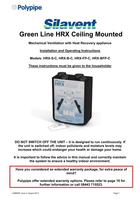
Silavent Green Line HRX Ceiling Mounted - Polypipe
Silavent Green Line HRX Ceiling Mounted - Polypipe
Silavent Green Line HRX Ceiling Mounted - Polypipe

Create successful ePaper yourself
Turn your PDF publications into a flip-book with our unique Google optimized e-Paper software.
1.2 Physical specification1.3 Optional main featuresnet weight 11.5kg1.3.1 Summer bypass (<strong>HRX</strong>-B-C, <strong>HRX</strong>-FB-C models)The models listed above will be supplied with an additional Winter/Summer switch (seehighlighted option boxes on the appliance cardboard cover). When the switch is set tosummer, the fresh air is no longer pre-warmed by the heat in the outgoing stale air. Additionalfresh outdoor air will also be supplied to the living areas. Important: when the switch is set tosummer, both fans will stop for 45 seconds to allow the internal bypass doors to open.1.3.2 Frost protection (<strong>HRX</strong>-FP-C, <strong>HRX</strong>-BFP-C models)The models listed above are supplied with an automatic frost protection system. Duringperiods of very cold weather, the fresh air supply fan will automatically turn off to reduce theload on your heating system and avoid possible freezing of the heat exchanger. During theseperiods, the extract fan will speed up slightly to maintain an even air pressure. See alsosection 2.3.LAB983R, Issue 3, August 2013 Page 6
2.0 Installation2.1 Overview2.1.1 The following instructions are intended to help prevent hazards. Installation should only becarried out by a qualified electrician and competent persons in clean, dry conditions wheredust and humidity are at minimum levels.Note: we advise installers to fix all mains, switch and sensor wiring prior to fixing the <strong>HRX</strong>ceiling unit in position (in accordance with the latest edition of the Wiring Regulations). Forconvenience, buried cables for the wiring centre should terminate in a 2 gang metal box ordry-lining box. The wiring centre can be fixed directly onto the box using standard M3.5screws (not supplied).2.2 Preparation2.2.1 When accepting delivery of the appliance, inspect for transit damage. If in doubt, call ourCustomer Services team on 08443 715523.2.2.2 The <strong>HRX</strong> ceiling appliance is as the name suggests is designed to be fitted directly to aceiling or within a ceiling void with a minimum clear depth of 350mm.2.2.3 Ensure that the position chosen for the wiring centre is close enough to the <strong>HRX</strong> ceilingappliance so that there is no undue strain applied to the cables between the appliance andthe wiring centre. Important: these cables can not be lengthened or shortened.2.2.4 Appropriate screw fixings to suit the support medium will need to be supplied by the installer.The support bracket is pre-drilled to suit 6 x 4mm (No.8) pan/round head screws.2.2.5 Ensure that there is sufficient space for the wiring centre, condensation fittings and ductwork.2.2.6 Ensure that there is sufficient space to access the filters and for carrying out any futuremaintenance on the appliance.2.2.7 The <strong>HRX</strong> ceiling appliance must be connected to the duct work as shown below; ductconnections can not be substituted.2.2.8 When viewed from the duct connection end, the duct configurations are as shown on thediagram below:LAB983R, Issue 3, August 2013 Page 7
2.3 Installing the frost protection sensor (<strong>HRX</strong>-FP-C, <strong>HRX</strong>-BFP-C models)2.3.1 Important: This operation must be carried out before fitting the angled mounting bracket.2.3.2 Referring to the diagram at 2.2.8; remove the filter cap nearest to and in line with the ‘INTAKEAIR FROM OUTSIDE’ duct connection socket.2.3.3 Insert the frost sensor filter cover and gently push the cable into the groove running up theface of the main housing. Ensure that no undue stress is put on the cable.2.3.4 See also 3.2 for wiring centre connections.2.4 Fitting the <strong>HRX</strong> ceiling unit2.4.1 Using a 13mm spanner/socket, remove the central nut and washer and then slide out thesupport bracket stud from the rear.2.4.2 Refer to the diagram on page 6 to determine where the extents of the <strong>HRX</strong> ceiling unit are inrelation to the support bracket. Using the support bracket as a template, mark the positionsfor the six fixings.2.4.3 Using 6 x 4mm (No.8) pan/round head screws and appropriate anchors (not supplied), securethe support bracket ensuring it is evenly touching the support surface. Do not over-tighten thescrews.2.4.4 Slide the <strong>HRX</strong> ceiling appliance onto the support bracket stud and refit the central nut andwasher. Ensure that no cables are trapped behind the <strong>HRX</strong> ceiling appliance and that theappliance is installed horizontally from side to side and at an angle of 3º downwards towardsthe condensate drain.2.4.5 Attach the four black self-adhesive ‘hook’ pads, one onto each corner indentation of the mainbody. Attach the four white self-adhesive ‘loop’ pads, one to each corner of the cardboardhouseholder-instruction’ cover. Carefully fit the ‘householder-instruction’ cover by pressing toengage the ‘hook and loop’ pads.LAB983R, Issue 3, August 2013 Page 8
2.5 Fitting the Domus 297 condensate drain kit2.5.1 Using a small amount of solvent weld suitable for ABS pipe fittings (not supplied), attach thethreaded socket to the selected condensate outlet spigot (see no 2.1.9). Important: follow thehealth and safety and user instructions supplied with the solvent weld. This is particularlyimportant when working in confined spaces.2.5.2 When the threaded socket is secure, fit and hand-tighten the threaded elbow, making surethat the rubber seal washer is seated correctly. Important: the threaded elbow may besubstituted for an in-line threaded fitting (not supplied). Gently push the waterless trap ontothe elbow stem. Important: check that the arrows printed on the trap point away from the<strong>HRX</strong> ceiling appliance (in the direction of flow) and prior to fitting, ensure that the waterlesstrap operates correctly by running a trickle of water from a tap through the trap in the directionof the arrows.2.5.3 Using the remainder of the kit items, complete the condensate drain-system to suit thedwelling layout. Important: the drain must incorporate a continuous fall of approximately 5º(87mm in every 1000mm) to the nearest waste water network.2.5.4 The condensate drain system should be adequately supported and suitably insulated if itpasses through unheated spaces and voids (e.g. loft spaces) to prevent freezing.Straight threaded connectornot suppliedLAB983R, Issue 3, August 2013 Page 9
2.6 Fitting the wiring centre2.6.1 Remove the cover of the wiring centre by removing the four retaining screws while taking carenot to dislodge any of the cables.2.6.2 Carefully remove sufficient knock-out panels in the mounting plate to provide access for themains supply, switch and external sensor cables.Either;2.6.3 Pass the cables through the knock-outs and push the mounting plate firmly against themounting surface. Using 2 x M3.5 electrical screws (not supplied) through the upper fixingholes, attach the mounting plate to the 2 gang metal box or dry-ling box already installed (notsupplied).Or;2.6.4 Pass the cables through the knock-outs and push the mounting plate firmly against themounting surface. Using the mounting plate as a template, mark the positions for the twolower fixing holes. Using 2 x 3mm (No.6) round or pan head screws and appropriate anchors(not supplied), secure the mounting plate.2.6.5 Make the wiring connections – see section 3.02.6.6 Refit the cover.2.7 Ducting guidelines2.7.1 Please refer to the design drawings for the proposed ducting layout.2.7.2 Four Ø125mm diameter sockets are provided for connecting the ducting. Ductwork should besecurely connected to the sockets using Domus DDSEAL acrylic sealant; failure to do thiswill cause unnecessary air leakage and impair performance. Ducting must be connected to allfour sockets according to left or right-hand configuration (see 2.2.7).2.7.3 Where ducts pass through unheated areas and voids (e.g. loft spaces) it must be insulatedusing Domus Thermal duct insulation in order to comply with The Building Regulations.Additionally, both ducts connecting the <strong>HRX</strong> ceiling to outside must be insulated whenpassing through heated areas to avoid condensation forming on the outside of the ducts.2.7.4 Alternative proprietary duct insulation may be used provided it complies with the 2010Domestic Ventilation Compliance Guide.2.7.5 When passing through a fire-stopping wall or fire-compartment wall, Domus FireBrakeintumescent duct connectors should be used in order to comply with The BuildingRegulations.2.7.6 Alternative proprietary fire-stopping methods may be employed provided they comply withApproved Document B of The Building Regulations.2.7.7 Rigid ducting – install using the least number of fittings to minimise resistance to airflow.Important: do not reduce the ducting size below Ø125mm diameter or 204mm x 60mmrectangular. All duct runs should be as short and as straight as possible for maximumperformance.2.7.8 Flexible ducting – ensure flexible ducting lengths are kept to a minimum and ducting is pulledtaut so that it is smooth and straight. Where bends are necessary and where ducting runs inrestricted areas, ensure that the ducting is not crushed. Mechanically fix flexible ducts usingLAB983R, Issue 3, August 2013 Page 10
2.7.9 Domus 125-5 hose clips and tape seal using Domus 50TP45 duct tape or any good qualityproprietary duct tape for added air-tightness.2.7.10 The fresh supply air must be drawn in from the exterior of the property. If drawn through awall, a Domus 905 airbrick or Domus 5904 fixed louvred grille should be fitted. If drawn inthrough the roof a Domus 4411 universal roof terminal should be fitted or a proprietary roofterminal designed for mechanical ventilation with a free area of at least 11500mm².2.7.11 The stale extract air must be expelled to the exterior of the property. If expelled through awall, a Domus 905 airbrick or Domus 5904 fixed louvred grille should be fitted. If expelledthrough the roof a Domus 4411 universal roof terminal should be fitted or a proprietary roofterminal designed for mechanical ventilation with a free area of at least 11500mm².2.7.12 It is recommended that the fresh supply and stale exhaust external inlets and outlets shouldbe fitted at least 2m apart to avoid recirculation of stale exhaust air.2.7.13 Further details regarding installation can be found in the 2010 Domestic VentilationCompliance Guide.3.0 Electrical3.1 Overview3.1.1 WARNING: This appliance must be earthed.3.1.2 Important: All wiring must conform to the latest edition of BS7671: IEE WiringRegulations.3.1.3 Important: The electrical installation must be carried out by a qualified electrician.3.1.4 This appliance is suitable for 230V 50Hz single phase supply only, fused at 3 Amps.3.1.4 A double-pole switch having a minimum contact separation of 3mm must be used to provideisolation for the appliance.3.1.5 Refer to page 14 for <strong>HRX</strong>-S-C wiring diagram, page 15 for <strong>HRX</strong>-B-C wiring diagram, page 16for <strong>HRX</strong>-FP-C wiring diagram and page 17 for <strong>HRX</strong>-BFP-C wiring diagram.3.1.6 Supplementary sensor diagrams are shown on page 18.3.1.7 External wiring (1.5mm² max.) and isolators to be supplied by others.LAB983R, Issue 3, August 2013 Page 11
3.2 Frost protection only, wiring-centre fan connections (<strong>HRX</strong>-FP-C, <strong>HRX</strong>-BFP-C models)3.2.1 Important: the fan selected as SUPPLY FRESH AIR TO ROOMS must be connected asshown in the diagram below.3.3 Summer bypass with fresh air filtration (<strong>HRX</strong>-B-C and <strong>HRX</strong>-BFP-C models)3.3.1 If filtration of the fresh air during summer bypass is a requirement for health reasons,separate the plug and socket labelled SUMMER BYPASS adjacent to the FRESH AIRSPIGOTS shown in the diagram below.LAB983R, Issue 3, August 2013 Page 12
4.0 Commissioning4.1.1 Overview4.1.2 When the wiring connections have been checked, switch on the mains supply and check thatthe system is operating correctly. The unit should switch between low and boost speeds usingthe manual boost switch (see 1.1.2).4.1.3 Airflow rates will need to be set at each room’s air-valve in accordance with the 2010Domestic Ventilation Compliance Guide to balance the system. Airflow measurements shouldbe performed using a calibrated airflow measuring device and the results recorded in litresper second (l/s) onto the Inspection Checklist and Airflow Measurement Test Sheet containedwithin the 2010 Domestic Ventilation Compliance Guide. The most common method uses avane anemometer, or similar, placed in a hood which completely covers the air-valve tomeasure the extract or supply airflow rate. The instrument should be calibrated annually byreturning the instrument to a UKAS accredited calibration centre and be capable of achievingan accuracy of ±5%.4.1.4 Each room airflow rate will need to be recorded on the Inspection Checklist and AirflowMeasurement Test Sheet. A completed copy must accompany these instructions and behanded over to the dwelling owner upon completion of the installation.4.2 System balancingFully open all of the air valvesSwitch the system to boostClose all internal and external doors and windowsMeasure the total air volume of the extract valves (wet rooms)Remove the rubber tamper-deterrent cap and using a small screwdriver, adjust the‘boost’ control on the wiring centre to achieve the total design extract rateAdjust individual room air valves to achieve the individual room design extract ratesSwitch the system to lowMeasure the total air volume of the supply valves (habitable rooms)Remove the rubber tamper-deterrent cap and using a small screwdriver, adjust the‘low’ control on the wiring centre to achieve the total design supply rateAdjust individual room air valves to achieve the individual room design supply ratesUsing the lock nuts fitted to the air valves, lock in positionRefit the rubber tamper-deterrent caps to the lid of the wiring centreLAB983R, Issue 3, August 2013 Page 13
<strong>HRX</strong>-B-C wiring diagramLAB983R, Issue 3, August 2013 Page 15
<strong>HRX</strong>-BFP-C wiring diagramLAB983R, Issue 3, August 2013 Page 17
Auxiliary control wiring diagramsELE150R – SWITCHED LIVEEXTENSION BOARDANC108A – OVERRUN TIMERANC802 – HUMIDISTAT WITH TIMER,ANC808A – HUMIDISTAT WITH PULLCORD,ANC846A IN DUCT HUMIDITY SENSORANC813A – PIR WITH OVERRUNTIMERNOTE:-TERMINALS 7 & 8 IN THE WIRING CENTRE ARE AVAILABLE FOR EXTERNAL SENSORS ANDSWITCHES TO PROVIDE BOOST FUNCTIONIMPORTANT: CONNECTIONS TO THESE TERMINALS MUST HAVE CLEARLY LABELLEDISOLATORS SITUATED ADJACENT TO THE WIRING CENTRELAB983R, Issue 3, August 2013 Page 18
5.0 Maintenance5.1 Routine maintenance5.1.2 The appliance G3/EU3 filters should be cleaned on a regular basis, the exact frequency willbe determined by individual living conditions, but we recommend inspection every 3,000hours (4 months) with replacement every 27,000 hours (three years).5.1.3 Before cleaning the filters, turn off the appliance at the isolator switch.5.1.4 To remove the two filters, pull out the two caps from the front of the appliance and gently slideout the filters in their carrier frames.5.1.5 Lightly vacuum the filters to remove surface debris and then gently wash through in warmsoapy water. Ensure that the filters are completely dry before refitting. Important: do not dryon a radiator or use excessive heat as this will distort the carrier frames.6.0 WarrantyLIMITED TWO YEAR WARRANTYIn the event that any problem or fault develops with the product due to faulty materials orworkmanship during the two year period beginning on the date on which you purchased the productthen subject to the various limitations and exclusions as detailed below, <strong>Polypipe</strong> will as soon asreasonably possible either repair or replace the product during its usual working hours or, at<strong>Polypipe</strong>’s discretion, provide you with a refund of the purchase price which you paid for the product.If you need to make a claim under this warranty then please contact <strong>Polypipe</strong> using one of thefollowing methods:<strong>Polypipe</strong> VentilationSandall Stones RoadKirk Sandall Industrial EstateKirk Sandall, DoncasterDN3 1QR, UKTel: 08443 715523Fax: 08443 715524International Tel: +44 (0)1302 348878International Fax: +44 (0)1302 348879Email: vent.info@polypipe.comThe above warranty does not apply to nor cover the repair of any problem or fault with the productwhich arises as a result of: (a) failure to install, operate, maintain and/or repair the product or anyassociated parts and components (including any ducting) using reasonable skill and care and inaccordance with the instructions provided with it (unless the original installation, maintenance orrepair which gave rise to the problem or fault was carried out by or on the behalf of <strong>Polypipe</strong> in whichcase this exclusion will not apply); (b) use of the product for any purposes other than those for whichit is designed; (c) modifications made to the product by anyone other than <strong>Polypipe</strong> or its approvedcontractors; (d) deliberate damage; and/or (e) damage caused by fire, flood or other water damage,explosions, rust or corrosion.<strong>Polypipe</strong> may carry out the repair or replacement of the product itself or using an approved subcontractorbut will always remain liable to you for the acts or omissions of any such sub-contractor asif those were the acts or omissions of <strong>Polypipe</strong> itself.Where you have purchased the product acting in your capacity as a consumer then the abovewarranty is offered by <strong>Polypipe</strong> in addition to and is not intended to affect or lessen those statutoryrights which you became entitled to as a consumer when you purchased the product. In the UK youcan find out more about your rights as a consumer by visiting the website of the Citizen’s AdviceBureau (http://www.adviceguide.org.uk/england/consumer_e.htm).In addition to this two year warranty <strong>Polypipe</strong> also offers extended warranty protection for thisproduct for consumers based in the UK subject to additional terms and conditions. You can find outmore about this extended warranty cover and purchase by contacting <strong>Polypipe</strong> using one of theabove methods.LAB983R, Issue 3, August 2013 Page 19
Installer contact details:Company name:Contact name:Tel:Email:Notes :<strong>Polypipe</strong> VentilationSandall Stones RoadKirk Sandall Industrial EstateKirk SandallDoncasterDN3 1QRUKTel: 08443 715523Fax: 08443 715524International Tel: +44 (0)1302 348878International Fax: +44 (0)1302 348879Have you considered an extendedwarranty package, for extra peace ofmind?<strong>Polypipe</strong> offer extended warrantyoptions.Please refer to page 19 for furtherinformation or call our CustomerService Department on 08443 715523.Email: vent.info@polypipe.comWeb: www.polypipe.com/ventilationE&OELAB983R, Issue 3, August 2013 Page 20