

Wiring Diagrams - Docs.hvacpartners.com
Wiring Diagrams - Docs.hvacpartners.com
Wiring Diagrams - Docs.hvacpartners.com

You also want an ePaper? Increase the reach of your titles
YUMPU automatically turns print PDFs into web optimized ePapers that Google loves.
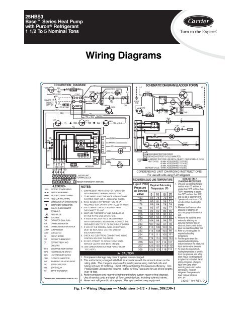
25HBS3Baset Series Heat Pumpwith Puronr Refrigerant11/2To5NominalTons<strong>Wiring</strong> <strong>Diagrams</strong>*CHS208/230 1ØPOWERSUPPLYCONNECTION DIAGRAMBLKorREDRED or BLK*LPSL1L2EQUIP GNDBLKBLKBLK*CHCOMPSCBLKRYELYELBLUHCFCAPYELBLU+t°YEL*ST*SCBRN*DTS*HPSYEL REDRED BLU YEL or BLUYELBLKCONT11 2123 23BLKYELYEL/BLUYEL or BLUBRNOFM1 2BLU5*SREQUIPGNDL1* CHSO OW2R RSCHEMATIC DIAGRAM (LADDER FORM)CONT11 21* CH5 21*SROFMDROF1 OF2RVS*SCDFTHCFCOMPC RCSDFT*ST+t°CAPLOGICCONT23 23L2DROF1OF2CBC Y O W2 RYEL WHTBLK ORN REDC Y O W2 R E L W3SPEED UPC Y O W2 R E L G-LEGEND-FACTORY POWER WIRINGFIELD POWER WIRINGFACTORY CONTROL WIRINGFIELD CONTROL WIRINGCONDUCTOR ON CIRCUIT BOARDCOMPONENT CONNECTION1/4-INCH QUICK CONNECTTERMINALSFIELD SPLICEJUNCTIONCAP CAPACITOR (DUAL RUN)*CH CRANKCASE HEATER*CHS CRANKCASE HEATER SWITCHCOMP COMPRESSORCONT CONTACTORCB CIRCUIT BOARDDFT DEFROST THERMOSTATDR DEFROST RELAY ANDCIRCUITRY*DTS DISCHARGE TEMP. SWITCH*HPS HIGH PRESSURE SWITCH*LPS LOW PRESSURE SWITCHOFM OUTDOOR FAN MOTORRVS REVERSING VALVE SOLENOID*SC START CAPACITOR*SR START RELAY*ST START THERMISTOR* MAY BE FACTORY OR FIELD INSTALLEDGLOGIC30 60 90 W1HK32EA001INDOOR UNITTERMINAL BLOCKINDOOR THERMOSTAT (NOTE #5)NOTES:YT1CDFTCORORNYEL/BLUBRN/YELORNPNKPNKDFTRVS1. COMPRESSOR AND FAN MOTOR FURNISHEDWITH INHERENT THERMAL PROTECTION.2. TO BE WIRED IN ACCORDANCE WITH NATIONALELECTRIC CODE (N.E.C.) AND LOCAL CODES.3. N.E.C. CLASS 2, 24 V CIRCUIT, MIN. 40 VAREQUIRED, 60VA ON UNITS INSTALLED WITH LLS.4. USE COPPER CONDUCTORS ONLY FROMDISCONNECT TO UNIT.5. MUST USE THERMOSTAT AND SUB-BASE ASSTATED IN PRE-SALE LITERATURE.6. IF INDOOR SECTION HAS A TRANSFORMERWITH A GROUNDED SECONDARY, CONNECT THEGROUNDED SIDE TO "C" ON THE CIRCUIT BOARD.7. IF ANY OF THE ORIGINAL WIRE, AS SUPPLIED,MUST BE REPLACED, USE THE SAME OREQUIVALENT WIRE.8. CHECK ALL ELECTRICAL CONNECTIONS INSIDECONTROL BOX FOR TIGHTNESS.9. DO NOT ATTEMPT TO OPERATE UNIT UNTILSERVICE VALVES HAVE BEEN OPENED.10. USE CONDUCTORS SUITABLE FOR AT LEAST75ºC (167ºF).Y YC*LPSDRT1*DTS9060 FIELD SELECTED TIME PERIODBETWEEN DEFROST CYCLES (MINUTES)30SPEED JUMPERED TEST PINS (USE METAL OBJECT), FIELD SPEED-UP CYCLEUP HEAT CYCLE: 90 MIN. ACCELERATED TO 21 SEC.60 MIN. ACCELERATED TO 14 SEC.30 MIN. ACCELERATED TO 7 SEC.DEFROST CYCLE: 10 MIN. ACCELERATED TO 2 SEC.CONDENSING UNIT CHARGING INSTRUCTIONSFor use with units using R-22 refrigerantREQUIRED LIQUID LINE TEMPERATURE COOLING ONLYCHARGING PROCEDURELiquid (PSIG)1. Only use sub cooling chargingRequired Subcooling method when OD ambient isPressure Temperature (ºF) greater than 70ºF and less thanat Service100ºF, indoor temp is greaterValve 5 10 15 20 than 70ºF and less than 80ºF,163 83 78 73 68 and line set is less than 80 ft.2. Operate unit a minimum of 15171 86 81 76 71 minutes before checking the179 89 84 79 74 charge.187 92 87 82 77 3. Measure liquid service valve196 95 90 85 80 pressure by attaching anaccurate gauge to the service205 98 93 88 83 port.214 101 96 91 86 4. Measure the liquid line temperatureby attaching an223 104 99 94 89233 107 102 97 92 accurate thermistor type orelectronic thermometer to the243 110 105 100 95 liquid line near the outdoor coil.253 113 108 103 98 5. Refer to unit rating plate for264 116 111 106 101 required subcoolingtemperature.274 119 114 109 104 6. Find the point where the285 122 117 112 107 required subcooling temperatureintersects the measured297 125 120 115 110 liquid service valve pressure.309 128 123 118 113 7. To obtain the required subcoolingtemperature at specificCAUTIONliquid line pressure, add refrigerantif liquid line temperatureis higher than indicated. Whenadding refrigerant, charge inliquid form using a flowrestricting device into suctionservice port. Recoverrefrigerant if temperature islower. Allow a toleranceof +/- 3ºF.332037-101 REV. D1. Compressor damage may occur if system is over charged.2. This unit is factory charged with R-22 in accordance with the amount shown on therating plate. The charge is adequate for most systems using matched coils andtubing not over 15 feet long. Check refrigerant charge for maximum efficiency. SeeProduct Data Literature for required Indoor air Flow Rates and for use of line lengthsover 15 feet.3. Relieve pressure and recover all refrigerant before system repair or final disposal.Use all service ports and open all flow-control devices, including solenoid valves.4. Never vent refrigerant to atmosphere. Use approved recovery equipment.Fig. 1 – <strong>Wiring</strong> Diagram — Model sizes 1 -1/2 - 5 tons, 208/230 -1*HPSCONTC
208/230 3ØPOWERSUPPLYL2L1BLUALERT!L3(NOTE #11)EQUIP GND* CHS BLKor BLKREDBLK-LEGEND-CAP*CH*CHSCOMPCONTCBDFTDR*HPS*LPSOFMPRMRVS*CHBLKOF1OF2CBPRM L1 L3 L2CONT 24V COMYELDRYELBLK*LPSYELC Y O W2 RYEL WHTORN REDC Y O W2 R EYELBRN/YELBLK or REDL W3 GC Y O W2 R E L GFACTORY POWER WIRINGFIELD POWER WIRINGFACTORY CONTROL WIRINGFIELD CONTROL WIRINGCONDUCTOR ON CIRCUITBOARDCOMPONENT CONNECTION1/4 - INCH QUICK CONNECTTERMINALSFIELD SPLICEJUNCTIONCAPACITORCRANKCASE HEATERCRANKCASE HEATER SWITCHCOMPRESSORCONTACTORCIRCUIT BOARDDEFROST THERMOSTATDEFROST RELAY ANDCIRCUITRYHIGH PRESSURE SWITCHLOW PRESSURE SWITCHOUTDOOR FAN MOTORPHASE ROTATION MONITORREVERSING VALVESOLENOID* MAY BE FACTORY OR FIELD INSTALLED.CONNECTION DIAGRAMLOGIC60120 9030HK32EA001BLUCONTCOMPT1 T211 21 BLKT313 23YELCAPYELOFMBLKBRNBLKYELBLUSPEEDUP*HPSINDOOR UNITTERMINAL BLOCKINDOOR THERMOSTAT(NOTE #5)NOTES:YT1CCODFTRYEL/BLUBRN/YELBRN/YELYEL/BLUYEL/BLUBLU or YELORNRVSORN ORNorORNorBLK BLKPNKPNKBLK BLKorPNKorPNKDFT1. Compressor and fan motor furnished withinherent thermal protection.2. To be wired in accordance with NationalElectric Code (N.E.C.) and local codes.3. N.E.C. class 2, 24V circuit, min. 40 VA required.4. Use copper conductors only, from disconnectto unit.5. Must use thermostat and sub-base as statedin pre-sale literature.6. If indoor section has a transformer with agrounded secondary, connect the groundedside to "C" on the circuit board.7. If any of the original wire, as supplied, mustbe replaced, use the same or equivalent wire.8. Check all electrical connections inside controlbox for tightness.9. Do not attempt to operate unit until servicevalves have been opened.10. It is imperative to connect 3Ø field powerto unit with correct phasing. The PhaseRotation Monitor will not allow the contactorto be energized if thephasing is not correct.If phasing is reversed, simply interchange any twoof the three power connections on the field side.11. Use conductors suitable for at least 75ºC (167ºF).EQUIPGNDO OW2R RCY YSCHEMATIC DIAGRAM(LADDER FORM)*LPSDRDFTRVST190FIELD SELECTED TIME PERIOD6030 BETWEEN DEFROST CYCLES (MINUTES)SPEEDUP JUMPERED TEST PINS (USE METAL OBJECT), FIELD SPEED-UP CYCLEHEAT CYCLE: 90 MIN. ACCELERATED TO 21 SEC.60 MIN. ACCELERATED TO 14 SEC.NOTEPRM LED INDICATOR30 MIN. ACCELERATED TO 7 SEC.DEFROST CYCLE: 10 MIN. ACCELERATED TO 2 SEC.OFF:ON:NO 24VACOKFLASH: PHASE PROBLEMDFTCLOGIC*HPSCONTCONDENSING UNIT CHARGING INSTRUCTIONSFor use with units using R-22 refrigerantCAUTION1. Compressor damage may occur if system is over charged.2. This unit is factory charged with R-22 in accordance with the amount shown on therating plate. The charge is adequate for most systems using matched coils and tubing notover 15 feet long. See product data literature for required indoor air flow rates and for useof line lengths over 15 Ft.3. Relieve pressure and recover all refrigerant before system repair or final unit disposal.Use all service ports and open all flow-control devices, including solenoid valves.L1*CHSCONT11 21*CHOF1 DR OF2REQUIRED LIQUID LINE TEMPERATURELiquid (PSIG)Required SubcoolingPressure Temperature (ºF)at ServiceValve1631711791871962052142232332432532642742852973095 10 15 2083 78 73 6886 81 76 7189 84 79 7492 87 82 7795 90 85 8098 93 88 83101 96 91 86104 99 94 89107 102 97 92110 105 100 95113 108 103 98116 111 106 101119 114 109 104122 117 112 107125 120 115 110128 123 118 113COMPT1T3OFMFig. 2 – <strong>Wiring</strong> Diagram — Model size 2 -1/2 - 5 tons, 208/230 -3T2PRML3CAPL2L1CONT23 13L2PRMCONT 24V COMCOOLING ONLYCHARGING PROCEDURE330758-101 REV. CCL31. Only use sub cooling charging method whenOD ambient is greater than 70ºF and lessthan 100ºF, indoor temp is greater than 70ºFand less than 80ºF, and line set is less than80 ft.2. Operate unit a minimum of 15 minutes beforechecking the charge.3. Measure liquid service valve pressure byattaching an accurate gauge to the serviceport.4. Measure the liquid line temperature byattaching an accurate thermistor type orelectronic thermometer to the liquid line nearthe outdoor coil.5. Refer to unit rating plate for requiredsubcooling temperature.6. Find the point where the required subcoolingtemperature intersects the measuredliquid service valve pressure.7. To obtain the required subcoolingtemperature at specific liquid line pressure,add refrigerant if liquid line temperatureis higher than indicated. When addingrefrigerant, charge in liquid form using a flowrestricting device into suction service port.Recover refrigerant if temperature islower. Allow a tolerance of +/- 3ºF.2
L2BLU460 3ØL1POWERSUPPLYL3ALERT!(NOTE #11)EQUIP GNDBLK or REDBLK* CHSPRMBLK*LPSYEL/BLU YEL-LEGEND-CAP*CH*CHSCOMPCONTCBDFTDR*HPS*LPSOFMOFRPRMRVS*CHOF1OF2CBDRBLKL1 L3 L2CONT 24V COMBLK or REDYELC Y O W2 RYEL WHTORN REDC Y O W2 R EYELL W3 GC Y O W2 R E L GFACTORY POWER WIRINGFIELD POWER WIRINGFACTORY CONTROL WIRINGFIELD CONTROL WIRINGCONDUCTOR ON CIRCUITBOARDCOMPONENT CONNECTION1/4 - INCH QUICK CONNECTTERMINALSFIELD SPLICEJUNCTIONCAPACITORCRANKCASE HEATERCRANKCASE HEATER SWITCHCOMPRESSORCONTACTORCIRCUIT BOARDDEFROST THERMOSTATDEFROST RELAY ANDCIRCUITRYHIGH PRESSURE SWITCHLOW PRESSURE SWITCHOUTDOOR FAN MOTOROUTDOOR FAN RELAYPHASE ROTATION MONITORREVERSING VALVESOLENOID* MAY BE FACTORY OR FIELD INSTALLED.CONNECTION DIAGRAMCONTBLUCOMPT1 T211 21BLKBLKT313 23 YELCAPYELOFMOFRBLKBRNBRN/YEL1 3YELLOGIC60120 9030HK32EA001BRN/YELBLUSPEEDUP*HPSDFTRINDOOR UNITTERMINAL BLOCKINDOOR THERMOSTAT(NOTE #5)YT1CCOBRN/YELBLKYEL/BLUBLU or YELYEL/BLUYEL/BLUBRN/YELORNRVSORN ORNorORNorBLK BLKPNKPNKBLK BLKorPNKorPNKDFTNOTES:1. Compressor and fan motor furnished withinherent thermal protection.2. To be wired in accordance with NationalElectric Code (N.E.C.) and local codes.3. N.E.C. class 2, 24V circuit, min. 40 VA required.4. Use copper conductors only, from disconnectto unit.5. Must use thermostat and sub-base as statedin pre-sale literature.6. If indoor section has a transformer with agrounded secondary, connect the groundedside to "C" on the circuit board.7. If any of the original wire, as supplied, mustbe replaced, use the same or equivalent wire.8. Check all electrical connections inside controlbox for tightness.9. Do not attempt to operate unit until servicevalves have been opened.10. It is imperative to connect 3Ø field powerto unit with correct phasing. The PhaseRotation Monitor will not allow the contactorto be energized if thephasing is not correct.If phasing is reversed, simply interchange any twoof the three power connections on the field side.11. Use conductors suitable for at least 75ºC (167ºF).EQUIPGNDL1* CHSO OW2R RCY YSCHEMATIC DIAGRAM(LADDER FORM)CONT11 21* CH*LPS9060OFRDROFMCOMPRVSFIELD SELECTED TIME PERIODBETWEEN DEFROST CYCLES (MINUTES)30SPEEDUP JUMPERED TEST PINS (USE METAL OBJECT), FIELD SPEED-UP CYCLEHEAT CYCLE: 90 MIN. ACCELERATED TO 21 SEC.60 MIN. ACCELERATED TO 14 SEC.NOTE30 MIN. ACCELERATED TO 7 SEC.DEFROST CYCLE: 10 MIN. ACCELERATED TO 2 SEC.T1T3T2CAPOF1 DR OF2DFTT1PRMCDFTLOGIC*HPSOFRCONTCONDENSING UNIT CHARGING INSTRUCTIONSFor use with units using R-22 refrigerantREQUIRED LIQUID LINE TEMPERATURELiquid (PSIG)Required SubcoolingPressure Temperature (ºF)at ServiceValve1631711791871962052142232332432532642742852973095 10 15 2083 78 73 6886 81 76 7189 84 79 7492 87 82 7795 90 85 8098 93 88 83101 96 91 86104 99 94 89107 102 97 92110 105 100 95113 108 103 98116 111 106 101119 114 109 104122 117 112 107125 120 115 110128 123 118 113CAUTION1. Compressor damage may occur if system is over charged.2. This unit is factory charged with R-22 in accordance with the amount shown on the ratingplate. The charge is adequate for most systems using matched coils and tubing not over15 feet long. Check refrigerant charge for maximum efficiency. See Product DataLiterature for required Indoor air Flow Rates and for use of line lengths over 15 feet.3. Relieve pressure and recover all refrigerant before system repair or final disposal. Use allservice ports and open all flow-control devices, including solenoid valves.4. Never vent refrigerant to atmosphere. Use approved recovery equipment.Fig. 3 – <strong>Wiring</strong> Diagram — Model size 3 - 5 tons, 460/3L3CONT23 13L2L1L2C333234-101 REV. BL3PRMCONT 24V COMPRM LED INDICATORO FF: NO 24V A CON : OKFLASH: PHASE PROBLECOOLING ONLYCHARGING PROCEDURE1. Only use sub cooling charging method whenOD ambient is greater than 70ºF and lessthan 100ºF, indoor temp is greater than 70ºFand less than 80ºF, and line set is less than80 ft.2. Operate unit a minimum of 15 minutes beforechecking the charge.3. Measure liquid service valve pressure byattaching an accurate gauge to the serviceport.4. Measure the liquid line temperature byattaching an accurate thermistor type orelectronic thermometer to the liquid line nearthe outdoor coil.5. Refer to unit rating plate for requiredsubcooling temperature.6. Find the point where the required subcoolingtemperature intersects the measuredliquid service valve pressure.7. To obtain the required subcoolingtemperature at specific liquid line pressure,add refrigerant if liquid line temperatureis higher than indicated. When addingrefrigerant, charge in liquid form using a flowrestricting device into suction service port.Recover refrigerant if temperature islower. Allow a tolerance of +/- 3ºF.3
Copyright 2009 Carrier Corp. S 7310 W. Morris St. S Indianapolis, IN 46231Printed in U.S.A. Edition Date: 09/09Manufacturer reserves the right to change, at any time, specifications and designs without notice and without obligations.Catalog No: 25HBS3---1WReplaces: New4


