Installation Instructions - Carrier
Installation Instructions - Carrier
Installation Instructions - Carrier
- No tags were found...
You also want an ePaper? Increase the reach of your titles
YUMPU automatically turns print PDFs into web optimized ePapers that Google loves.
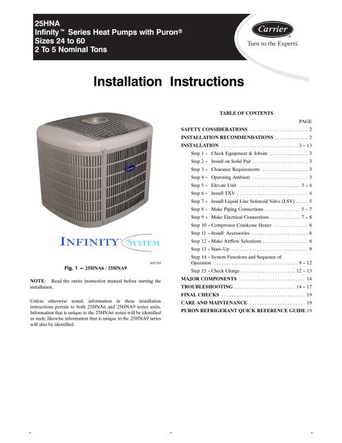
25HNAInfinityt Series Heat Pumps with PuronrSizes 24 to 602To5NominalTons<strong>Installation</strong> <strong>Instructions</strong>Fig. 1 --- 25HNA6 / 25HNA9A05240NOTE: Read the entire instruction manual before starting theinstallation.Unless otherwise noted, information in these installationinstructions pertain to both 25HNA6 and 25HNA9 series units.Information that is unique to the 25HNA6 series will be identifiedas such; likewise information that is unique to the 25HNA9 serieswill also be identified.TABLE OF CONTENTSPAGESAFETY CONSIDERATIONS ....................... 2INSTALLATION RECOMMENDATIONS ............. 2INSTALLATION .............................. 3-13Step 1 - Check Equipment & Jobsite ............... 3Step 2 - Install on Solid Pad ...................... 3Step 3 - Clearance Requirements .................. 3Step 4 - Operating Ambient ...................... 3Step 5 - Elevate Unit ........................ 3 - 4Step 6 - Install TXV ............................ 4Step 7 - Install Liquid Line Solenoid Valve (LSV) ..... 5Step 8 - Make Piping Connections .............. 5 - 7Step 9 - Make Electrical Connections ............ 7 - 8Step 10 - Compressor Crankcase Heater ............. 8Step 11 - Install Accessories ...................... 8Step 12 - Make Airflow Selections .................. 8Step 13 - Start-Up .............................. 9Step 14 - System Functions and Sequence ofOperation ................................. 9 - 12Step 15 - Check Charge ..................... 12 - 13MAJOR COMPONENTS .......................... 14TROUBLESHOOTING ........................ 14 - 17FINAL CHECKS ................................. 19CARE AND MAINTENANCE ...................... 19PURON REFRIGERANT QUICK REFERENCE GUIDE 19
25HNASAFETY CONSIDERATIONSImproper installation, adjustment, alteration, service,maintenance, or use can cause explosion, fire, electrical shock, orother conditions which may cause death, personal injury, orproperty damage. Consult a qualified installer, service agency, oryour distributor or branch for information or assistance. Thequalified installer or agency must use factory -authorized kits oraccessories when modifying this product. Refer to the individualinstructions packaged with the kits or accessories when installing.Follow all safety codes. Wear safety glasses, protective clothing,and work gloves. Use quenching cloth for brazing operations.Have fire extinguisher available. Read these instructionsthoroughly and follow all warnings or cautions included inliterature and attached to the unit. Consult local building codesand National Electrical Code (NEC) for special requirements.Recognize safety information. This is the safety -alert symbol !When you see this symbol on the unit and in instructions ormanuals, be alert to the potential for personal injury. Understandthese signal words; DANGER, WARNING, and CAUTION.These words are used with the safety -alert symbol. DANGERidentifies the most serious hazards which will result in severepersonal injury or death. WARNING signifies hazards whichcould result in personal injury or death. CAUTION is used toidentify unsafe practices which may result in minor personalinjury or product and property damage. NOTE is used tohighlight suggestions which will result in enhanced installation,reliability, or operation.! WARNINGELECTRICAL SHOCK HAZARDFailure to follow this warning could result in personalinjury or death.Before installing, modifying, or servicing system, mainelectrical disconnect switch must be in the OFF position.There may be more than 1 disconnect switch. Lock outand tag switch with a suitable warning label.! WARNINGUNIT OPERATION AND SAFETY HAZARDFailure to follow this warning could result in personal injuryor equipment damage.PuronR refrigerant systems operate at higher pressures thanstandard R -22 systems. Do not use R -22 service equipmentor components on PuronR refrigerant equipment.INSTALLATION RECOMMENDATIONSNOTE: In some cases noise in the living area has been traced togas pulsations from improper installation of equipment.1. Locate unit away from windows, patios, decks, etc. whereunit operation sound may disturb customer.2. Ensure that vapor and liquid tube diameters areappropriate for unit capacity.3. Run refrigerant tubes as directly as possible by avoidingunnecessary turns and bends.4. Leave some slack between structure and unit to absorbvibration.5. When passing refrigerant tubes through the wall, sealopening with RTV or other pliable silicon -based caulk.(See Fig. 2.)6. Avoid direct tubing contact with water pipes, duct work,floor joists, wall studs, floors, and walls.7. Do not suspend refrigerant tubing from joists and studswith a rigid wire or strap which comes in direct contactwith tubing.(See Fig. 2.)8. Ensure that tubing insulation is pliable and completelysurrounds vapor tube.9. When necessary, use hanger straps which are 1 in. wideand conform to shape of tubing insulation. (See Fig. 2.)10. Isolate hanger straps from insulation by using metalsleeves bent to conform to shape of insulation.When outdoor unit is connected to factory -approved indoor unit,outdoor unit contains system refrigerant charge for operation withARI rated indoor unit when connected by 15 ft. of field -suppliedor factory accessory tubing. For proper unit operation, checkrefrigerant charge using charging information located on controlbox cover and/or in the Check Charge section of this instruction.IMPORTANT: Maximum liquid -line size is 3/8 -in. OD for allresidential applications including long line applications.IMPORTANT: Always install the factory -supplied liquid -linefilter drier. Obtain replacement filter driers from your distributoror branch.2
OUTDOOR WALLCAULKINSTALLATIONNOTE: Avoid contact between tubing and structureINDOOR WALLLIQUID TUBEINSULATIONHANGER STRAP(AROUND VAPORTUBE ONLY)THROUGH THE WALLVAPOR TUBEJOISTINSULATIONVAPOR TUBE1” MIN.SUSPENSIONFig. 2 --- Connecting Tube <strong>Installation</strong>LIQUID TUBEA94026Specifications for this unit in residential new construction marketrequire the outdoor unit, indoor unit, refrigerant tubing sets,metering device, and filter drier listed in presale literature. Therecan be no deviation. Consult the Service Manual – AirConditioners and Heat Pumps Using Puron® Refrigerant toobtain required unit changes for specific applications and forR -22 retrofit.STEP 1 —Check Equipment and Job SiteUnpack UnitMove to final location. Remove carton taking care not to damageunit.Inspect EquipmentFile claim with shipping company prior to installation if shipmentis damaged or incomplete. Locate unit rating plate on unit cornerpanel. It contains information needed to properly install unit.Check rating plate to be sure unit matches job specifications.STEP 2 —Install on a Solid, Level Mounting PadIf conditions or local codes require the unit be attached to pad, tiedown bolts should be used and fastened through knockoutsprovided in unit base pan. Refer to unit mounting pattern in Fig.3 to determine base pan size and knockout hole location.For hurricane tie downs, contact distributor for details and PECertification (Professional Engineer), if required.On rooftop applications, mount on level platform or frame. Placeunit above a load -bearing wall and isolate unit and tubing setfrom structure. Arrange supporting members to adequatelysupport unit and minimize transmission of vibration to building.Consult local codes governing rooftop applications.Roof mounted units exposed to winds above 5 mph may requirewind baffles. Consult the Service Manual - Residential SplitSystem Air Conditioners and Heat Pumps Using Puron®Refrigerant for wind baffle construction.UNIT BASE PANDIMENSIONSTIEDOWN KNOCKOUT LOCATIONSA B C36-1/2x40 11 -5/8 6 -13/16 28 -3/429 -1/2 X 33 10–1/16 5–5/8 23–3/4Fig. 3 --- Tiedown Knockout LocationsA05242NOTE: Unit must be level to within ±2° (±3/8 in./ft.) percompressor manufacturer specifications.STEP 3 —Clearance RequirementsWhen installing, allow sufficient space for airflow clearance,wiring, refrigerant piping, and service. Allow 30 -in. clearance toservice end of unit and 48 in. above unit. For proper airflow, a6 -in. clearance on 1 side of unit and 12 in. on all remaining sidesmust be maintained. Maintain a distance of 24 in. between units.Position so water, snow, or ice from roof or eaves cannot falldirectly on unit.On rooftop applications, locate unit at least 6 in. above roofsurface.STEP 4 —Operating AmbientThe minimum outdoor operating ambient in cooling mode is55°F without low ambient cooling enabled and the maximumoutdoor operating ambient in cooling mode is 125°F. OnInfinityt communicating systems only (for both 25HNA6 and25HNA9), low ambient cooling is available to 0°F.The maximum outdoor operating ambient in heating mode is66°F on all models. Continuous operation in the heating mode isapproved to -30_F.STEP 5 —Elevate Unit!CAUTIONUNIT OPERATION HAZARDFailure to follow this caution may result in equipmentdamage or improper operation.Do not allow water and/or ice to build up in base pan.Elevate unit per local climate and code requirements to provideclearance above estimated snowfall level and ensure adequatedrainage of unit.25HNA3
25HNA!CAUTIONUNIT OPERATION HAZARDFailure to follow this caution may result in equipmentdamage or improper operation.Locate the unit in such a way that it is stable in allcircumstances including adverse weather conditions.STEP 6 —Install TXVNOTE: Applies to non -TXV indoor units only. If installing arated and approved indoor coil without a factory installedPuronR TXV, remove and replace the fixed orifice or R -22 TXVexpansion device with a hard shutoff Puron TXV.The thermostatic expansion valve is specifically designed tooperate with Puron® refrigerant. Do not use an R -22 TXV. Anexisting R -22 TXV must be replaced with a factory -approvedTXV specifically designed for Puron refrigerant. Refer toProduct Data Digest for the appropriate TXV kit number.!CAUTIONUNIT OPERATION HAZARDFailure to follow this caution may result in equipmentdamage or improper operation.All indoor coil units must be installed with a hard shutoff PuronR TXV metering device.IMPORTANT: The TXV should be mounted as close to theindoor coil as possible and in a vertical, upright position. Avoidmounting the inlet tube vertically down. Valve is moresusceptible to malfunction due to debris if inlet tube is facingdown. A factory -approved filter drier must be installed in theliquid line.Installing TXV in Place of Piston1. Pump system down to 2 psig and recover refrigerant.2. Remove hex nut from piston body. Use backup wrench onfan coils.3. Remove and discard factory -installed piston. Be sureTeflon seal is in place.4. Reinstall hex nut. Finger tighten nut plus 1/2 turn.NOTE: If the piston is not removed from the body, TXV willnot function properly.!CAUTIONEQUIPMENT DAMAGE HAZARDFailure to follow this caution may result in equipmentdamage or improper operation.Use a brazing shield and wrap TXV with wet cloth oruse heat sink material.5. Install TXV on indoor coil liquid line. Sweat swiveladapter to inlet of indoor coil and attach to TXV outlet.Use backup wrench to avoid damage to tubing or valve.Sweat inlet of TXV, marked “IN” to liquid line. Avoidexcessive heat which could damage valve.6. Install vapor elbow with equalizer adapter to suction tubeof line set and suction connection to indoor coil. Adapterhas a 1/4 -in. male connector for attaching equalizer tube.47. Connect equalizer tube of TXV to 1/4 -in. equalizer fittingon vapor line adapter.8. Attach TXV bulb to horizontal section of suction lineusing clamps provided. Insulate bulb with field -suppliedinsulation tape. See Fig. 4 for correct positioning ofsensing bulb.9. Proceed with remainder of unit installation.10 O'CLOCK2 O'CLOCKSUCTION TUBESTRAPSENSING BULB8 O'CLOCK 4 O'CLOCK7⁄ 8 IN. OD & SMALLER LARGER THAN 7 ⁄ 8 IN. ODA81032Fig. 4 --- Position of Sensing BulbReplacing TXV on R -22 Indoor Coil1. Pump system down to 2 psig and recover refrigerant.2. Remove coil access panel and fitting panel from front ofcabinet.3. Remove TXV support clamp using a 5/16 -in. nut driver.Save the clamp.4. Remove R -22 TXV using a backup wrench on flareconnections to prevent damage to tubing.5. Using wire cutters, cut equalizer tube off flush with vaportube inside cabinet.6. Remove bulb from vapor tube inside cabinet.7. Braze equalizer stub -tube closed. Use protective barrier asnecessary to prevent damage to drain pan.IMPORTANT: Route the equalizer tube of Puron TXV throughsuction line connection opening in fitting panel prior to replacingfitting panel around tubing.8. Install TXV with 3/8 -in. copper tubing through small holein service panel. Use wrench and backup wrench, to avoiddamage to tubing or valve, to attach TXV to distributor.9. Reinstall TXV support clamp (removed in item 3).10. Attach TXV bulb to vapor tube inside cabinet, in samelocation as original was when removed, using suppliedcopper bulb clamps. See Fig. 4 for correct positioning ofsensing bulb.11. Route equalizer tube through suction connection opening(large hole) in fitting panel and install fitting panel inplace.12. Sweat inlet of TXV, marked “IN” to liquid line. Avoidexcessive heat which could damage valve.13. Install vapor elbow with equalizer adapter to vapor line ofline set and vapor connection to indoor coil. Adapter hasa 1/4 -in. male connector for attaching equalizer tube.14. Connect equalizer tube of TXV to 1/4 -in. equalizer fittingon vapor line adapter. Use backup wrench to preventdamage to equalizer fitting.15. Proceed with remainder of unit installation.
STEP 7 —In Long -Line Applications, Install Liquid -LineSolenoid Valve (LSV)For refrigerant piping arrangements with equivalent lengthsgreater than 80 ft. and/or when elevation difference betweenindoor and outdoor unit is greater than ±20 ft., follow allrequirements of the Long -Line Guideline—Air Conditioners andHeat Pumps Using PuronR refrigerant. If required byLong -Line Guideline, install LSV kit, part no. KHALS0401LLS,specifically designed for PuronR refrigerant heat pumps. LSVshould be installed within 2 ft. of outdoor unit with flow arrowpointing toward outdoor unit. Follow the <strong>Installation</strong> <strong>Instructions</strong>included with accessory kit.IMPORTANT: Flow arrow must point toward outdoor unit.STEP 8 —Make Piping Connections! WARNINGPERSONAL INJURY AND UNIT DAMAGEHAZARDFailure to follow this warning could result in personalinjury or death.Relieve pressure and recover all refrigerant beforesystem repair or final unit disposal. Use all serviceports and open all flow -control devices, includingsolenoid valves.!CAUTIONUNIT DAMAGE HAZARDFailure to follow this caution may result in equipmentdamage or improper operation.Do not leave system open to atmosphere any longer thanminimum required for installation. POE oil in compressor isextremely susceptible to moisture absorption. Always keepends of tubing sealed during installation.!CAUTIONUNIT DAMAGE HAZARDFailure to follow this caution may result in equipmentdamage or improper operation.If ANY refrigerant tubing is buried, provide a 6 in. verticalrise at service valve. Refrigerant tubing lengths up to 36 in.may be buried without further special consideration. Donot bury lines longer than 36 in.!CAUTIONUNIT DAMAGE HAZARDFailure to follow this caution may result in equipmentdamage or improper operation.Observe the following:S Use a brazing shield.S Wrap service valves with wet cloth or use a heat sinkmaterial.Outdoor units may be connected to indoor section usingaccessory tubing package or field -supplied refrigerant gradetubing of correct size and condition. For tubing requirementsbeyond 80 ft., substantial capacity and performance losses canoccur. Following the recommendations in the ApplicationGuideline and Service Manual -Residential Split -System AirConditioners and Heat Pumps Using PuronR Refrigerant willreduce these losses. Refer to Table 1 for field tubing diameters.Refer to Table 2 for accessory requirements.Outdoor Unit Connected to Factory -Approved Indoor Unit:Outdoor unit contains correct system refrigerant charge foroperation with factory approved ARI rated indoor unit withhighest sales volume when connected by 15 ft. of field -suppliedor factory -accessory tubing, and factory supplied filter drier.Check refrigerant charge for maximum efficiency.25HNATable 1—Refrigerant Connections and Recommended Liquid and Vapor Tube Diameters (In.)Information is Specific to 25HNA6 and 25HNA9 ModelsUNIT SIZEConnectionDiameterLIQUIDTubeDiameterConnectionDiameterRATED VAPOR(up to 80 ft. T.E.L)TubeDiameter25HNA624 3/8 3/8 5/8 5/825HNA636 3/8 3/8 3/4 3/425HNA648 3/8 3/8 7/8 7/825HNA660 3/8 3/8 7/8 1-1/825HNA924 3/8 3/8 3/4 3/425HNA936 3/8 3/8 3/4 7/825HNA948 3/8 3/8 7/8 7/825HNA960 3/8 3/8 7/8 1-1/8Notes:1. Tube diameters are for total equivalent lengths (T.E.L.) up to 80 ft. Consult the Long Line Guideline—Air Conditioners and Heat Pumps using Puron®... refrigerant.2. Do not apply capillary tube or the fixed orifice indoor coils to these units.3. T.E.L. --- Total Equivalent Length5
Table 2—Accessory Usage25HNAAccessoryREQUIRED FOR LOW---AMBI-ENT APPLICATIONS(Below 55 °F)REQUIRED FOR LONG LINEAPPLICATIONS*(Over 80 ft.)REQUIRED FOR SEACOAST APPLICATIONS(Within 2 miles)Crankcase Heater Standard Standard StandardEvaporator Freeze ProtectionStandard with Infinity Control(Low Ambient not allowed with non---NoNocommunicating thermostat)Winter Start ControlStandard with Infinity Control(Low Ambient not allowed with non---communicating thermostat)NoNoCompressor Start Assist Capacitorand Relay}Standard on 25HNA6 models.Not required on 25HNA9 modelssince compressor always startsunloaded.Standard on 25HNA6 models.Not required on 25HNA9 modelssince compressor always startsunloaded.Standard on 25HNA6models.Not required on 25HNA9models since compressoralways starts unloaded.Low---Ambient ControlStandard with Infinity Control (Lowambient not allowed with non---communicatingNoNothermostat)Support Feet Recommended No RecommendedLiquid Line Solenoid Valve No Yes NoBall Bearing Fan Motor Standard Standard StandardPuron Balance Port Hard Shut---OffTXVYes{ Yes{ Yes{* For Tubing Set lengths between 80 and 200 ft. horizontal or 20 ft. vertical differential (Total Equivalent Length), refer to the Long Line Guideline—Air ConditionersandHeatPumpsusingPuron®refrigerant.{Required on all indoor units. Standard on all new Puron refrigerant fan coils and furnace coils.} Information is specific to 25HNA6 and 25HNA9 models.Install Liquid -Line Filter Drier IndoorRefrigerant Tubing connection OutdoorRefer to Fig. 5 and install filter drier as follows:Connect vapor tube to fitting on outdoor unit vapor service1. Braze 5 -in. liquid tube to the indoor coil.valves (see Table 1).Install Adapter Tube2. Wrap filter drier with damp cloth.3. Braze filter drier to above5 -in.liquid tube.Flow arrow mustpoint towards indoor coil.4. Connect and braze liquid refrigerant tube to the filter drier.!CAUTIONUNIT DAMAGE HAZARDFailure to follow this caution may result in equipment damageor improper operation.<strong>Installation</strong> of filter drier in liquid line is required.1. Remove plastic retainer holding outdoor piston in liquidservice valve.2. Check outdoor piston size with matching number listed onunit rating plate.3. Locate plastic bag taped to unit containing adapter tube.4. 4. Remove TeflonR washer from bag and install onopen end of liquid service valve.5. Remove adapter tube from bag and connect threaded nutto liquid service valve. Tighten nut finger tight and thenwith wrench tighten an additional 1/2 turn (15 ft -lb).DO NOT OVERTIGHTEN!Sweat Connections!CAUTIONUNIT DAMAGE HAZARDFailure to follow this caution may result in equipmentdamage or improper operation.Service valves must be wrapped in a heat-sinkmaterial such as a wet cloth.Fig. 5 --- Liquid Line Filter DrierA05227Use refrigerant grade tubing. Service valves are closed fromfactory and ready for brazing. After wrapping service valve witha wet cloth, braze sweat connections using industry acceptedmethods and materials. Consult local code requirements.Refrigerant tubing and indoor coil are now ready for leak testing.This check should include all field and factory joints.6
Evacuate Refrigerant Tubing and Indoor Coil!CAUTIONUNIT DAMAGE HAZARDFailure to follow this caution may result in equipmentdamage or improper operation.Never use the system compressor as a vacuum pump.Refrigerant tubes and indoor coil should be evacuated using therecommended deep vacuum method of 500 microns. Thealternate triple evacuation method may be used if the procedureoutlined below is followed. Always break a vacuum with drynitrogen.Deep Vacuum MethodThe deep vacuum method requires a vacuum pump capable ofpulling a vacuum of 500 microns and a vacuum gage capable ofaccurately measuring this vacuum depth. The deep vacuummethod is the most positive way of assuring a system is free of airand liquid water. (See Fig. 6)MICRONS500045004000350030002500200015001000500LEAK INSYSTEM0 1 2 3 4 5 6 7MINUTESTriple Evacuation MethodFig. 6 --- Deep Vacuum GraphVACUUM TIGHTTOO WETTIGHTDRY SYSTEMA95424A95424The triple evacuation method should only be used when vacuumpump is only capable of pumping down to 28 in. of mercuryvacuum and system does not contain any liquid water. Refer toFig. 7 and proceed as follows:1. Pump system down to 28 in. of mercury and allow pumpto continue operating for an additional 15 minutes.2. Close service valves and shut off vacuum pump.3. Connect a nitrogen cylinder and regulator to system andopen until system pressure is 2 psig.4. Close service valve and allow system to stand for 1 hr.During this time, dry nitrogen will be able to diffusethroughout the system absorbing moisture.5. Repeat this procedure as indicated in Fig. 7. System willthen be free of any contaminants and water vapor.EVACUATEBREAK VACUUM WITH DRY NITROGENWAITEVACUATEBREAK VACUUM WITH DRY NITROGENWAITEVACUATECHECK FOR TIGHT, DRY SYSTEM(IF IT HOLDS DEEP VACUUM)CHARGE SYSTEMFig. 7 --- Triple Evacuation MethodFinal Tubing CheckA95425IMPORTANT: Check to be certain factory tubing on bothindoor and outdoor unit has not shifted during shipment. Ensuretubes are not rubbing against each other or any sheet metal. Payclose attention to feeder tubes, making sure wire ties on feedertubes are secure and tight.STEP 9 —Make Electrical Connections! WARNINGELECTRICAL SHOCK HAZARDFailure to follow this warning could result in personalinjury or death.Do not supply power to unit with compressor terminalbox cover removed.Be sure field wiring complies with local and national fire, safety,and electrical codes, and voltage to system is within limits shownon unit rating plate. Contact local power company for correctionof improper voltage. See unit rating plate for recommendedcircuit protection device.NOTE: Operation of unit on improper line voltage constitutesabuse and could affect unit reliability. See unit rating plate. Donot install unit in system where voltage may fluctuate above orbelow permissible limits.NOTE: Use copper wire only between disconnect switch andunit.NOTE: Install branch circuit disconnect of adequate size perNEC to handle unit starting current. Locate disconnect withinsight from and readily accessible from unit, per Section 440 -14of NEC.Route Ground and Power WiresRemove access panel to gain access to unit wiring. Extend wiresfrom disconnect through power wiring hole provided and intounit control box.25HNA7
25HNA! WARNINGELECTRICAL SHOCK HAZARDFailure to follow this warning could result in personalinjury or death.The unit cabinet must have an uninterrupted or unbrokenground to minimize personal injury if an electrical faultshould occur. The ground may consist of electrical wire ormetal conduit when installed in accordance with existingelectrical codes.Connect Ground and Power WiresConnect ground wire to ground connection in control box forsafety. Connect power wiring to contactor as shown in Fig. 8.DISCONNECTPER N. E. C. AND/ORLOCAL CODESFIELD POWERWIRINGFIELD GROUNDWIRINGGROUNDLUGCONTACTORA91056Fig. 8 --- Line Power ConnectionsConnect Control WiringRoute low voltage control wires through control wiring grommetand connect leads to control board.For 25HNA9 models, connect to Infinity connections ABCDonly. Standard non -communicating thermostats are not allowedunless it is an emergency that User Interface is not workingproperly and new User Interface is not available. For emergencyuse, connect to standard thermostat connections R, C, W, Y1, Y2,and O.NOTE: When unit is operating in emergency mode, STATUSlight will flash rapidly. Unit will operate in high stage ONLY.For 25HNA6 models, connect to ABCD for Infinity Control orstandard thermostat connections R, C, W1, Y1, Y2, and O.General InformationUse No. 18 AWG color-coded, insulated (35°C minimum) wirefor all installations.All wiring must be NEC Class 1 and must be separated fromincoming power leads.Use furnace transformer, fan coil transformer, or accessorytransformer for control power, 24v/40va minimum. The outdoorunit requires a minimum of 27va/24vac control power.Final Wiring CheckIMPORTANT: Check factory wiring and field wire connectionsto ensure terminations are secured properly. Check wire routingto ensure wires are not in contact with tubing, sheet metal, etc.STEP 10 —CompressorCrankcaseHeaterFurnish power to crankcase heater a minimum of 24 hr beforestarting unit. To furnish power to heater only, set thermostat toOFF and close electrical disconnect to outdoor unit.NOTE: On 25HNA6 models, starting the compressor without aminimum of 12 hours of crankcase heat prior to initial start -upmay result in a compressor chattering noise and possible damageto the compressor.STEP 11 —Install AccessoriesRefer to the individual instructions packaged with kits oraccessories when installing.STEP 12 —Make Airflow Selections for 25HNA6 SeriesOnly Using Non -Communicating (Non -Infinity) ThermostatsAirflow Selection for 58CVA/58MVB FurnacesThe 58CVA/58MVB variable speed furnaces provide high -andlow -stage blower operation to match the capacities of thecompressor at high and low stages. To select the recommendedairflow and for adjustments to the manual switches labeledSW1 -5, AC, and CF on the control board refer to the furnace<strong>Installation</strong>, Start-UP, and Operating <strong>Instructions</strong>. The58CVA/58MVB utilizes a control center that allows the installingtechnician to select the proper airflows. The HP switchdetermines the airflow during high stage compressor operation.Airflow for high - and low -stage can be calculated at either 350CFM per ton or 400 CFM per ton, based on the positions ofSW1 -5.When using communicating (Infinity) control, dipswitchadjustments are not necessary on furnaces. Airflows aredetermined by Infinity Control setup.Airflow Selection for FK4 or FV4 Fan Coils for 25HNA6Series Only Using Non -Communicating (Non -Infinity)ThermostatsThe FV4 provides high - and low -stage blower operation tomatch the capacities of compressor at high - and low -stage. Toselect recommended airflow, refer to FV4 <strong>Installation</strong><strong>Instructions</strong>. The FV4 utilizes an Easy Select control board thatallows the installing technician to select proper airflows. Foradjustments to control board, select appropriate HP SIZE andCFM ADJUST setting. This fan coil has an adjustable blower offdelay factory set at 90 sec for high - and low -stage bloweroperation.For other combinations of equipment Consult Product DataDigest.8
STEP 13 —Start-Up!CAUTIONUNIT OPERATION AND SAFETY HAZARDFailure to follow this caution may result in minor personalinjury, equipment damage or improper operation.Observe the following:S Do not overcharge system with refrigerant.S Do not operate unit in a vacuum or at negative pressure.S Do not disable low pressure switchS Dome temperatures may be hot.!CAUTIONPERSONAL INJURY HAZARDFailure to follow this caution may result in personal injury.Wear safety glasses, protective clothing, and gloves whenhandling refrigerant.!CAUTIONENVIRONMENTAL HAZARDFailure to follow this caution may result in environmentaldamage.Federal regulations require that you do not ventrefrigerant to the atmosphere. Recover during systemrepair or final unit disposal.Follow these steps to properly start up the system:1. After system is evacuated, fully back seat (open) liquidand vapor service valves.2. Unit is shipped with valve stem(s) front seated (closed)and caps installed. Replace stem caps after system isopened to refrigerant flow (back seated). Replace capsfinger-tight and tighten with wrench an additional 1/12turn.3. Close electrical disconnects to energize system.4. Set room thermostat or User Interface at desiredtemperature. Be sure set point is below indoor ambienttemperature and is set low enough to energize desiredstage.5. Set room thermostat or User Interface to COOL and fancontrol to ON or AUTO mode, as desired. Operate unit for15 minutes. Check system refrigerant charge.NOTE: For 25HNA6 Series only using non -communicating(non -Infinity) thermostat. <strong>Carrier</strong> electronic thermostats areequipped with a 15 -minute staging timer. This timer prevents thetwo -stage system from operating at high stage until unit has beenoperating in low stage for 15 minutes, unless there is at least a 5°Fdifference between room temperature and thermostat set point. Toforce high stage (after a minimum of 2 minutes in low stage),adjust the set point at least 5°F below room ambient.6. Set room thermostat or User Interface to HEAT or COOLand fan control to AUTO or ON, as desired. Wait forappropriate time delay(s). Operate unit for 15 minutes.Check refrigerant charge.STEP 14 —SYSTEM FUNCTIONS AND SEQUENCE OFOPERATIONThe outdoor unit control system has special functions. Thefollowing is an overview of the two -stage control functions:Cooling and Heating OperationThe 25HNA6 model utilizes either a standard indoor thermostator Infinity Communication User Interface. The 25HNA9 modelsutilize an Infinity communicating User Interface only. With a callfor first stage cooling, the outdoor fan, reversing valve, and lowstage compressor are energized. If low -stage cannot satisfycooling demand, high -stage cooling is energized by the secondstage of indoor thermostat or User Interface. After second stage issatisfied, the unit returns to low -stage operation until first stage issatisfied or until second stage is required again. When both firststage and second stage cooling are satisfied, the compressor willshut off. The reversing valve will remain energized until thecontrol board power is removed or a call for heating in initiated.With a call for heating, the outdoor fan and compressor areenergized. The compressor will operate in high or low stageoperation, as needed to meet the heating demand. When theheating demand is satisfied, the compressor and fan will shut off.The reversing valve is de -energized in the heating mode.NOTE: When two -stage unit is operating at low -stage, systemvapor (suction) pressure will be higher than a standardsingle-stage system or high -stage operation.NOTE: Outdoor fan motor will continue to operate for oneminute after compressor shuts off, when outdoor ambient isgreater than or equal to 100°F.NOTE: On 25HNA6 models, if unit has not operated within thepast 12 hours, or following a unit power-up, upon the nextthermostat high - or low -stage demand, unit operates for aminimum of 5 minutes in high -stage.On 25HNA6 models with non -communicating (non -Infinity)systems, with first stage of cooling, Y1 and O are powered on;and with second stage of cooling, Y1, Y2, and O are on. Forthese systems, with first stage of heating Y1 is on and for secondstage of heating, Y1 and Y2 are on. When the reversing valve isenergized, O is powered on.Communication and Status Function LightsFor Infinity Control only, Green communications (COMM)LightA green LED (COMM light) on the outdoor board (see Fig. 9)indicates successful communication with the other systemproducts. The green LED will remain OFF until communicationsis established. Once a valid command is received, the green LEDwill turn ON continuously. If not communication is receivedwithin 2 minutes, the LED will be turned OFF until the next validcommunication.Amber Status LightAn amber colored STATUS light is used to display the operationmode and fault codes as specified in the troubleshooting section.See Table 5 for codes and definitions.NOTE: Only one code will be displayed on the outdoor unitcontrol board (the most recent, with the highest priority).Utility InterfaceWith Infinity ControlThe utility curtailment relay should be wired between R and Y2connections on the control board for Infinity CommunicatingSystems only (see Fig. 9.) This input allows a power utilitydevice to interrupt compressor operation during peak loadperiods. When the utility sends a signal to shut the system down,the User Interface will display, “Curtailment Active”.925HNA
25HNAOne Minute Stage Change Time Delay on 25HNA6 ModelsWhen compressor changes stages from high to low or low tohigh, there is a 1 -minute time delay before compressor restarts.The outdoor fan motor remains running.Compressor Operation on 25HNA6 ModelsWhen the compressor operates in high stage operation, thecompressor motor rotates clockwise. Both the lower and upperpistons are eccentric with the rotating crankshaft and bothcompress refrigerant.When the compressor operates in low stage operation, thecompressor motor reverses direction (rotates counterclockwise).The lower piston becomes idle and the upper piston compressesrefrigerant. The start and run windings are reversed.Crankcase Heater OperationThe crankcase heater is energized during unit off cycle regardlessof outside air temperature (OAT) on 25HNA6 models.The crankcase heater is energized during off cycle below 65°F on25HNA9 models.Outdoor Fan Motor OperationThe outdoor unit control energizes outdoor fan any timecompressor is operating, except for defrost. The outdoor fanremains energized if a pressure switch or compressor overloadshould open. Outdoor fan motor will continue to operate for oneminute after the compressor shuts off when the outdoor ambientis greater than or equal to 100°F. On 25HNA6 models, theoutdoor fan remains energized during the 1 -minute compressorstaging time delay.Time DelaysThe unit time delays include:S Five minute time delay to start cooling or heatingoperation when there is a call from the thermostat oruser interface. To bypass this feature, momentarilyshort and release Forced Defrost pins.S Five minute compressor re-cycle delay on return froma brown -out condition.S Two minute time delay to return to standby operationfrom last valid communication (with Infinity only).S One minute time delay of outdoor fan at termination ofcooling mode when outdoor ambient is greater than orequal to 100_F.S Fifteen second delay at termination of defrost beforethe auxiliary heat (W1) is de -energized.S Twenty second delay at termination of defrost beforethe outdoor fan is energized.S Thirty second compressor delay when quiet shiftenabled.S On 25HNA6 models there is a 1 minute time delaybetween staging from low to high and from high to lowcapacity. On 25HNA9 models there is no delay; thecompressor will change from low to high and fromhigh to low capacity on the fly to meet the demand.Compressor Operation on 25HNA9 Models:When the compressor is operating in low stage, the modulatingring is de-activated, allowing two internal bypass ports to closeoff 33% of the scroll compression area, so the system operates atpart load capacity. The 24volt solenoid coil is de-energized inlow stage operation.When the compressor is operating in high stage, the modulatingring is activated, sealing the bypass ports, which allows thecompressor to operate at full load capacity. The 24volt solenoidcoil is energized in high stage operation. The 25HNA9 unitcontains a 230v to 24vac transformer to supply power to thesolenoid when it is energized. The compressor solenoid loadshould not be included in the system (furnace or fan coil) controlpower transformer sizing.10
25HNAUTILITY RELAY *UTILITY SIGNALOPEN RELAY* SUPPLIED BY UTILITY PROVIDERFig. 9 --- 2 -Stage Control BoardLLSLiquid Line SolenoidA05247GENERAL INFORMATIONLow Ambient CoolingWhen this unit is operating below 55_F outdoor temperature,provisions must be made for low ambient operation.Infinity Controlled low ambient cooling:This unit is capable of low ambient cooling without a kit ONLYwhen using Infinity control. A low ambient kit is not required,and the outdoor fan motor does not need to be replaced forInfinity controlled low ambient operation. The Infinity Controlprovides an automatic evaporator coil freeze protection algorithmthat eliminates the the need for an evaporator freeze thermostat.Low ambient cooling must be enabled in the User Interface setup. Fan may not begin to cycle until about 40_F OAT. Fan willcycle based on coil and outdoor air temperature.Infinity controlled low ambient mode operates as follows:S Fan is OFF when outdoor coil temp is < (outdoor airtemperature + 3 _F) or outdoor fan has been ON for 30minutes. (Fan is turned off to allow refrigerant system tostabilize.)S Fan is ON when outdoor coil temp > (outdoor airtemperature + 25_F) or outdoor coil temp > 80_F orifoutdoor fan has been OFF for 30 minutes. (Fan is turnedon to allow refrigerant system to stabilize.)S Low pressure switch is ignored for first 3 minutes duringlow ambient start up. After 3 minutes, if LPS trips, thenoutdoor fan motor is turned off for 10 minutes, with thecompressor running. If LPS closes within 10 minutesthen cooling continues with the outdoor fan cycling perthecoiltemperatureroutinelisted abovefor theremainderof the cooling cycle. If the LPS does not close within 10minutes, then the normal LPS trip response (shut downcooling operation and generate LPS trip error) will occur.DefrostThis control offers 5 possible defrost interval times: 30, 60, 90,120 minutes, or AUTO.On 25HNA6 models, these are selected by dip switches on theunit control board or by the Infinity Control User Interface. TheInfinity Control selection overrides the control board dip switchsettings.On 25HNA9 , the defrost interval times: 30, 60, 90, and 120 -minutes or AUTO are selected by the Infinity Control UserInterface (the dip switches are not used.)AUTO defrost adjusts the defrost interval time based on the lastdefrost time as follows:S When defrost time 7 minutes, the next defrostinterval=30 minutes.The control board accumulates compressor run time. As theaccumulated run time approaches the selected defrost intervaltime, the control board monitors the coil temperature sensor for adefrost demand. If a defrost demand exists, a defrost cycle will beinitiated at the end of the selected time interval. A defrost demandexists when the coil temperature is at or below 32_F for 4minutes during the interval.The defrost cycle is terminated when the coil temperature reaches65_F or 10 minutes has passed.If the coil temperature does not reach 32_F within the interval,the interval timer will be reset and start over.S Upon initial power up the first defrost interval isdefaulted to 30 minutes. Remaining intervals are atselected times.S Defrost is only allowed to occur below 50_F outdoorambient temperature.11
25HNADefrost HoldOn 25HNA6 models, in a non -communicating system, if thethermostat becomes satisfied (Y1 or Y1 and Y2) before thedefrost cycle is terminated, the control will “Hold” in defrostmode and finish the defrost cycle on the next call for heat.On 25HNA6 models, with communicating Infinity Control andall 25HNA9 models, defrost hold is not needed in acommunicating system because the User Interface will completethe defrost cycle before shutting down the system.Forced DefrostOn 25HNA6 models with non -communicating (non -Infinity)control, forced defrost can be initiated by manually shorting the2 -pin header labeled FORCED DEFROST (see Fig 9) on thecontrol board for 5 seconds then releasing.On 25HNA6 and 25HNA9 with communicating (Infinity)control, forced defrost is initiated with the User Interface.On all models, during a Forced Defrost:S If coil temperature is at defrost temperature of 32_F,and outdoor air temperature is below 50_F, a fulldefrost sequence will occur.S If coil temperature or outdoor air temperature do notmeet the above requirements, an abbreviated 30 seconddefrost will occur.Quiet ShiftQuiet Shift is a field selectable defrost mode which may eliminateoccasional noise that could be heard at the start of the defrostcycle and restarting of the heating cycle. On 25HNA6 modelswith non -communicating system, this feature must be enabled byselecting the 3rd position of the 3 -position dip switch. For25HNA6 and 25HNA9 models with communicating (Infinity)systems, it must be enabled at the User Interface. When activated,the following sequence of operation will occur. Reversing valvewill energize and compressor will turn off for 30 seconds, thenturn back on to complete defrost. At the end of the defrost cycle,the reversing valve de-energizes, compressor will turn off foranother 30 seconds, and the fan will turn off for 40 seconds,before starting in the heating mode.Liquid Line Solenoid AccessoryIn heat pump long -line applications, a liquid line solenoid isrequired to control refrigerant migration in the heating mode. Thesolenoid should be installed near the outdoor unit with the arrowfacing the outdoor unit. This is the direction of flow control. Seeapplication manual for long -line application details.Accessory Liquid Solenoid with Infinity CommunicatingControl: When using the Infinity control, the liquid linesolenoid output is provided at the Y1 connection. Connect thesolenoid as shown in the wiring label diagram. This is a 24vacoutput that is energized whenever the compressor is energized. Itcloses, in the compressor off mode, to prevent refrigerantmigration into the unit through the liquid line.On 25HNA6 Models with Accessory Liquid Solenoid Using aNon -Communicating Thermostat: The liquid solenoid isconnect to the Y1 and C terminal connections. The liquidsolenoid closes, in the compressor off mode, to preventrefrigerant migration into the unit through the liquid line.STEP 15 —Check ChargeUnit ChargeFactory charge and charging method are shown on unitinformation plate. Charge Puron refrigerant units with cylinder ininverted position and a commercial -type metering device inmanifold hose. Charge refrigerant into suction line.NOTE: If subcooling charging conditions are not favorable,charge must be weighed in accordance with unit rating plate,±0.6 oz./ft. of 3/8 -in. liquid line above or below 15 ft.,respectively. Favorable conditions fall within the ranges given onthe charging chart on the outdoor unit plate.EXAMPLE:To calculate additional charge required for a 25 -ft. line set:25 ft. - 15 ft. = 10 ft. X 0.6 oz./ft. = 6 oz. of additional charge.Cooling Only ProcedureThis system requires charging by the subcooling method.1. On all unites, operate unit a minimum of 10 minutes inhigh stage before checking charge.On 25HNA6 models, charging in low stage may causecompressor chattering and possible damage to thecompressor.2. Measure liquid service valve pressure by attaching anaccurate gage to service port.3. Measure liquid line temperature by attaching an accuratethermistor type or electronic thermometer to liquid linenear outdoor coil.4. Refer to unit rating plate for required subcoolingtemperature. Subcooling amount is for high stageoperation.5. Refer to Table 3. Find the point where required subcoolingtemperature intersects measured liquid service valvepressure.6. To obtain required subcooling temperature at a specificliquid line pressure, add refrigerant if liquid linetemperature is higher than indicated or reclaim refrigerantif temperature is lower. Allow a tolerance of ±3°F.12
Heating Check Chart ProcedureTo check system operation during heating cycle, refer to the HeatPump Charging <strong>Instructions</strong> label on outdoor unit. This chartindicates whether a correct relationship exists between systemoperating pressure and air temperature entering indoor andoutdoor units. If pressure and temperature do not match on chart,system refrigerant charge may not be correct. Do not use chart toadjust refrigerant charge.NOTE: In heating mode, check refrigerant charge only whenpressures are stable. If in doubt, remove charge and weigh incorrect refrigerant charge.NOTE: When charging is necessary during heating season,charge must be weighed in accordance with unit rating plate,±0.6 oz./ft. of 3/8 -in. liquid line above or below 15 ft.,respectively.EXAMPLE:To calculate additional charge required for a 25 -ft. line set:25 ft. - 15 ft. = 10 ft. X 0.6 oz./ft. = 6 oz. of additional charge.Table 3—Required Liquid---Line Temperature (°F)LIQUID PRESSUREREQUIRED SUBCOOLING TEMPERATURE (°F)AT SERVICE VALVE(PSIG)8 10 12 14 16 18189 58 56 54 52 50 48195 60 58 56 54 52 50202 62 60 58 56 54 52208 64 62 60 58 56 54215 66 64 62 60 58 56222 68 66 64 62 60 58229 70 68 66 64 62 60236 72 70 68 66 64 62243 74 72 70 68 66 64251 76 74 72 70 68 66259 78 76 74 72 70 68266 80 78 76 74 72 70274 82 80 78 76 74 72283 84 82 80 78 76 74291 86 84 82 80 78 76299 88 86 84 82 80 78308 90 88 86 84 82 80317 92 90 88 86 84 82326 94 92 90 88 86 84335 96 94 92 90 88 86345 98 96 94 92 90 88354 100 98 96 94 92 90364 102 100 98 96 94 92374 104 102 100 98 96 94384 106 104 102 100 98 96395 108 106 104 102 100 98406 110 108 106 104 102 100416 112 110 108 106 104 102427 114 112 110 108 106 104439 116 114 112 110 108 106450 118 116 114 112 110 108462 120 118 116 114 112 110474 122 120 118 116 114 112486 124 122 120 118 116 114499 126 124 122 120 118 116511 128 126 124 122 120 11825HNA13
25HNAMAJOR COMPONENTS2 -Stage Control BoardThe HP control board controls the following functions:S High and low stage compressor contactor operationS Outdoor fan motor operationS Reversing valve operationS Defrost operationS Low ambient coolingS Crankcase heater operationS Compressor external protectionS Pressure switch monitoringS Time DelaysS On 25HNA6 models, high and low stage start relay andcapacitor operation (Bristol only)Field ConnectionsOn 25HNA6 models with non -communicating (non -Infinity)System, the two -stage control receives 24vac low -voltagecontrol system inputs through the R, C, Y1, Y2 and Oconnections located at the bottom of the control board (see Fig.9.) On a non -communicating system, output W1 is connected atthe bottom of the control board for auxiliary heat.On 25HNA6 models with communicating system and all25HNA9 models, use the ABCD Infinity Connections.Two Stage CompressorThe two stage compressor contains motor windings that provide2 -pole (3500 RPM) operation. Refer to Table 4 for correctwinding resistance.Compressor Internal ReliefThe compressor is protected by an internal pressure relief (IPR)which relieves discharge gas into the compressor shell whendifferential between suction and discharge pressure exceeds500 -550 psi on 25HNA6 models and 550 -625 psi on 25HNA9models. The compressor is also protected by an internal overloadattached to motor windings.Compressor Control ContactorsThe contactor(s) have a 24volt coil. The electronic control boardcontrols the operation of the appropriate contactor.TROUBLESHOOTINGSystems Communication FailureIf communication with the Infinity control is lost with the UserInterface, the control will flash the appropriate fault code. (SeeTable 5.) Check the wiring to the UI and the indoor and outdoorunits.Model PlugThe control board must have a valid model plug to operate. If avalid model plug is not detected, it will not operate and thecontrol will flash the appropriate fault code, shown in Table 5.Pressure Switch ProtectionThe outdoor unit is equipped with high - and low -pressureswitches. If the control senses the opening of a high or lowpressure switch, it will respond as follows:1. De-energize the appropriate compressor contactor2. Keep the outdoor fan operating for 15 minutes3. Display the appropriate fault code (see Table 5)4. After a 15 minute delay, if there is a call for cooling orheating and LPS or HPS is reset, the appropriatecompressor contactor is energized.5. If LPS or HPS has not closed after a 15 minute delay, theoutdoor fan is turned off. If the open switch closes anytimeafter the 15 minute delay, then resume operation with acall for cooling or heating.6. If LPS or HPS trips 3 consecutive cycles, the unitoperation is locked out for 4 hours.7. In the event of a high -pressure switch trip orhigh -pressure lockout, check the refrigerant charge,outdoor fan operation, and outdoor coil (in cooling) forairflow restrictions, or indoor airflow in heating.8. In the event of a low -pressure switch trip or low -pressurelockout, check the refrigerant charge and indoor airflow(cooling) and outdoor fan operation and outdoor coil inheating.Control FaultIf the outdoor unit control board has failed, the control will flashthe appropriate fault code (see Table 5). The control board shouldbe replaced.Brown -Out ProtectionIf the line voltage is less than 187v for at least 4 seconds, theappropriate compressor contactor and fan relay are de -energized.Compressor and fan operation are not allowed until voltage is aminimum of 190v. The control will flash the appropriate faultcode (see Table 5).230V Line (Power Disconnect) DetectionIf there is no 230v at the compressor contactor(s) when the indoorunit is powered and cooling or heating demand exists, theappropriate fault code is displayed. Verify the disconnect is closedand 230v wiring is connected to the unit.Compressor Voltage SensingThe control board input terminals labeled VS, VR and L2 on25HNA6 models and VS and L2 on 25HNA9 models (see Fig. 9)are used to detect compressor voltage status, and alert the user ofpotential problems. The control continuously monitors the highvoltage on the run capacitor of the compressor motor. Voltageshould be present any time the compressor contactor is energized,and voltage should not be present when the contactor isde -energized.14
Contactor Shorted DetectionIf there is compressor voltage sensed when there is no demand forcompressor operation, the contactor may be stuck closed or theremay be a wiring error. The control will flash the appropriate faultcode.25HNA6 Models, Compressor Thermal CutoutThe control senses the compressor voltage at VR and VS. Whenstarting or running, a phase difference of the voltages on theinputs will indicate the thermal protector is closed. If the phasedifference is 5 degrees or less for 10 seconds, the internalprotector is open. The control de-energizes the appropriatecompressor contactor for 15 minutes, but continues to operate theoutdoor fan. The control Status LED will flash the appropriatecode shown in table 5. After 15 minutes, with a call for low orhigh stage cooling or heating, the appropriate compressorcontactor is energized. If the thermal protector has not re -set, theoutdoor fan is turned off. If the call for cooling or heatingcontinues, the control will energize the compressor contactorevery 15 minutes. If the thermal protector closes, (at the next 15minute interval check), the unit will resume operation.If the thermal cutout trips for three consecutive cycles, then unitoperation is locked out for 4 hours and the appropriate fault codeis displayed.25HNA9 Compressor Thermal CutoutIf the control senses the compressor voltage after start-up, and isthen absent for 10 consecutive seconds while cooling or heatingdemand exists, the thermal protector is open. The controlde-energizes the compressor contactor for 15 minutes, butcontinues to operate the outdoor fan. The control Status LEDwill flash the appropriate code shown in table 5. After 15minutes, with a call for low or high stage cooling or heating, thecompressor contactor is energized. If the thermal protector hasnot re-set, the outdoor fan is turned off. If the call for cooling orheating continues, the control will energize the compressorcontactor every 15 minutes. If the thermal protector closes, (atthe next 15 minute interval check), the unit will resume operation.If the thermal cutout trips for three consecutive cycles, then unitoperation is locked out for 4 hours and the appropriate fault codeis displayed.Low or High Contactor Open (25HNA6 models) / No 230V atCompressor Contractor (25HNA9 models)If the compressor voltage is not sensed when the compressorshould be starting, the appropriate contactor may be stuck open orthere is a wiring error. The control will flash the appropriate faultcode. Check the contactor and control box wiring.25HNA6 Models Only - Compressor Start Detection onBristol Models OnlyIn low stage, if the specified start voltage at VR terminal is notachieved, the start relay is de -energized after 1 second and thecontrol will flash the appropriate fault code.In high stage, if the specified start voltage at VS terminal is notachieved, the start relay is de -energized after 1 second and thecontrol will flash the appropriate fault code.If the specified start voltage is not achieved for 3 consecutive lowstage starts, low stage operation is locked out for 30 minutes. Ifthe specified start voltage is not achieved for 3 consecutive highstage starts, high stage operation is locked out for 30 minutes.The control will flash the appropriate fault code.Troubleshooting 25HNA6 units for proper switching betweenlow & high stagesCheck the suction and liquid pressures at the service valves.Suction pressure should be reduced by 5 -10% when switchingfrom low to high capacity. There should be a 10 -20% increase inliquid pressure when switching from low to high capacity.Compressor current should increase 100 -250% when switchingfrom low to high stage.Troubleshooting 25HNA9 units for proper switching betweenlow & high stagesCheck the suction pressures at the service valves. Suctionpressure should be reduced by 3 -10% when switching from lowto high capacity.NOTE: The liquid pressures are very similar between low andhigh stage operation, so liquid pressure should not be used fortroubleshooting.Compressor current should increase 20 -45% when switchingfrom low to high stage. The compressor solenoid whenenergized in high stage, should measure 24vac.Temperature ThermistorsThermistors are electronic devices which sense temperature. Asthe temperature increases, the resistance decreases. Thermistorsare used to sense outdoor air (OAT) and coil temperature (OCT).Refer to Fig. 12 for resistance values versus temperature.If the outdoor air or coil thermistor should fail, the control willflash the appropriate fault code. (See Table 5.)IMPORTANT: The outdoor air thermistor and coil thermistorshould be factory mounted in the final locations. Check toinsure thermistors are mounted properly per Fig. 10 and Fig.11.Thermistor Sensor ComparisonThe control continuously monitors and compares the outdoor airtemperature sensor and outdoor coil temperature sensor to ensureproper operating conditions. The comparison is:S In cooling if the outdoor air sensor indicates ≥ 10_Fwarmer than the coil sensor (or) the outdoor air sensorindicates ≥ 20_F cooler than the coil sensor, the sensorsare out of range.S In heating if the outdoor air sensor indicates ≥ 35_Fwarmer than the coil sensor (or) the outdoor air sensorindicates ≥ 10_F cooler than the coil sensor, the sensorsare out of range.If the sensors are out of range, the control will flash theappropriate fault code as shown in Table 5.The thermistor comparison is not performed during low ambientcooling or defrost operation.Failed Thermistor Default OperationFactory defaults have been provided in the event of failure ofoutdoor air thermistor and/or coil thermistor.If the OAT sensor should fail, low ambient cooling will not beallowed and the one-minute outdoor fan off delay will not occur.Defrost will be initiated based on coil temperature and time.If the OCT sensor should fail, low ambient cooling will not beallowed. Defrost will occur at each time interval during heatingoperation, but will terminate after 5 minutes.If there is a thermistor out of range error, defrost will occur ateach time interval during heating operation, but will terminateafter 5 minutes.Count the number of short and long flashes to determine theappropriate flash code. Table 5 gives possible causes and actionsrelated to each error.25HNA15
OAT Thermistor must be locked inplace with spherical nib end facing towardsthe front of the control boxOCT Thermistormust be securedtight on stub tube.25HNAFig. 10 --- Outdoor Air Thermistor (OAT) AttachmentTHERMISTOR CURVEFig. 11 --- Outdoor Coil Thermistor (OCT) Attachment9080RESISTANCE (KOHMS)7060504030201000 20 40 60 80 100 120TEMPERATURE (DEG. F)Fig. 12 --- Resistance Values Versus TemperatureA91431Table 4—Two---Stage Compressor Resistances(Winding Resistance at 70_F±20_)Winding 25HNA6024 25HNA6036 25HNA6048 25HNA6060Start (S-C) 2.74 1.98 1.55 0.74Run (R-C) 0.80 0.75 0.48 0.36Winding 25HNA9024 25HNA9036 25HNA9048 25HNA9060Start (S-C) 1.40 1.29 1.52 0.60Run (R-C) 1.32 0.89 0.64 0.49Status CodesTable 5 shows the status codes flashed by the amber status light. Most system problems can be diagnosed by reading the status code asflashed by the amber status light on the control board.The codes are flashed by a series of short and long flashes of the status light. The short flashes indicate the first digit in the status code,followed by long flashes indicating the second digit of the error code. The short flash is 0.25 seconds ON and the long flash is 1.0 secondON. Time between flashes is 0.25 seconds. Time between short flash and first long flash is 1.0 second. Time between code repeating is 2.5seconds with LED OFF.EXAMPLE:3 short flashes followed by 2 long flashes indicates a 32 code. Table 5 shows this to be low pressure switch open.16
OPERATIONStandby – no call for unit operationNoneFAULTTable 5—TROUBLESHOOTINGAMBERLEDPOSSIBLE CAUSE AND ACTIONFLASHCODEOn solid,Normal operationno flashStandard ThermostatControltinuous flashtrol.Only high stage operation is available. This operatimg mode should beRapid, con-Unit being controlled by standard thermostat inputs instead of Infinity Con-Emergency Mode --- Model 25HNA9only(25HNA9 only)ing used in emergency situations only.Low Stage Cool/Heat Operation None 1, pause Normal operationHigh Stage Cool/Heat OperationNone 2, pause Normal operationSystem CommunicationsFailure16 Communication with user interface lost. Check wiring to UI, indoorand outdoor unitsInvalid ModelControl does not detect a model plug or detects an invalid model25Plugplug. Unit will not operate without correct model plug.High PressureHigh---pressure switch trip. Check refrigerant charge, outdoor fan31Switch Openoperation and coils for airflow restrictions.Low PressureLow pressure switch trip. Check refrigerant charge and indoor air32Switch OpenflowControl Fault 45Outdoor unit control board has failed. Control board needs to bereplaced.Brown Out (230Line voltage < 187v for at least 4 seconds. Compressor and fan46v)operation not allowed until voltage>190v. Verify line voltage.There is no 230v at the contactor when indoor unit is powered andNo 230v at Unit 47 cooling/heating demand exists. Verify the disconnect is closed and230v wiring is connected to the unit.Outdoor AirTemp SensorFaultOutdoor CoilSensor FaultThermistors outof rangeLow Stage ThermalCutoutHigh Stage ThermalCutoutContactorShortedNo 230V atCompressor(25HNA9 Only)Low Stage DidNot Start(25HNA6 Only)Low Stage DidNot Start 3 times(25HNA6Only)High Stage DidNot Start(25HNA6 Only)High Stage DidNot Start 3 times(25HNA6 Only)Low Stage ThermalLockoutHigh Stage ThermalLockoutLow PressureLockoutHigh PressureLockoutLow ContactorOpen(25HNA6 Only)High ContactorOpen(25HNA6 Only)5355567172737475767778818283848587Outdoor air sensor not reading or out of range. Ohm out sensorand check wiring.Coil sensor not reading or out of range. Ohm out sensor and checkwiring.Improper relationship between coil sensor and outdoor air sensor.Ohm out sensors and check wiring.No voltage phase difference is detected (on 25HNA6 models) orcompressor voltage sensed, then disappears (on 25HNA9 models)while cooling or heating demand exists. Possible causes are internalcompressor overload trip or start relay not releasing (if installed).No voltage phase difference is detected (on 25HNA6 models) orcompressor voltage sensed, then disappears (on 25HNA9 models)while cooling or heating demand exists. Possible causes are internalcompressor overload trip or start relay not releasing (if installed).Compressor voltage sensed when no demand for compressor operationexists. Contactor may be stuck closed or there is a wiringerror.Compressor voltage not sensed when compressor should be starting.Contactor may be stuck open or there is a wiring error.Specified start voltage at VR terminal was not achieved in low stage.Start relay was de---energized after 1 second.For3consecutivelowstagestarts,thespecifiedstartvoltageatVRterminal was not achieved & start relay was de---energized. Lowstage locked out for 30 minutes.Specified start voltage at VS terminal was not achieved in highstage. Start relay was de---energized after 1 second.For 3 consecutive high stage starts, the specified start voltage at VSterminal was not achieved & start relay was de---energized. Highstage locked out for 30 minutes.Thermal cutout occurs in three consecutive low/ high stage cycles.Low stage locked out for 4 hours or until 24v power recycled.Thermal cutout occurs in three consecutive high/low stage cycles.High stage locked out for 4 hours or until 24v power recycled.Low pressure switch trip has occurred during 3 consecutive cycles.Unit operation locked out for 4 hours or until 24v power recycled.High pressure switch trip has occurred during 3 consecutive cycles.Unit operation locked out for 4 hours or until 24v power recycled.Compressor voltage not sensed when compressor should be starting.Low stage contactor may be stuck open or there is a wiringerror.Compressor voltage not sensed when compressor should be starting.High stage contactor may be stuck open or there is a wiringerror.25HNA17
INDOOR CONTROL FAN COIL 2-SPEEDHEAT PUMPHybridHeatTWO -STAGERVS COOLINGO/W2OOHEAT/COOLSTAGE 1Y1/W2Y1Y1HEAT STAGE 3HEAT/COOLSTAGE 2W/W1Y/Y2W1W2W1REMOVE J2JUMPER FORHEAT STAGINGFANGY/Y2Y224 VAC HOTRGDEHUMIDIFYDHUMRDHRREMOVE J1 FORDEHUMIDIFYMODES25HNA24 VAC COMMHUMIDIFYRVS HEATINGOUTDOORSENSORCONNECTIONCHUMBS1S2CHUMIDIFIER(24 VAC)OUTDOORSENSORCA02005Fig. 13 --- Infinity Wiring with 2 -Stage Puron refrigerantHeat Pump (non -communicating)(applies to 25HNA6 Models Only)A06157Fig. 14 --- HybridHeatt Thermostat with Two -StageFurnace and Two -Stage Heat Pump (non -communicating)User InterfaceFan CoilCommunicating AC//HPDCBADCBADCBAHUMCCYOROATHumidifierW24vacFig. 9 - FE4A Fan Coil Wiring with 2-Speed AC/HPA03076Fig. 15 --- Infinity Furnace or Fan Coil Wiring with Communicating Two -Stage AC / HP18
FINAL CHECKSIMPORTANT: Before leaving job, be sure to do the following:1. Ensure that all wiring is routed away from tubing andsheet metal edges to prevent rub -through or wirepinching.2. Ensure that all wiring and tubing is secure in unit beforeadding panels and covers. Securely fasten all panels andcovers.3. Tighten service valve stem caps to 1/12 -turn past fingertight.4. Leave Users Manual with owner. Explain systemoperation and periodic maintenance requirements outlinedin manual.5. Fill out Dealer <strong>Installation</strong> Checklist and place incustomer file.CARE AND MAINTENANCEFor continuing high performance and to minimize possibleequipment failure, periodic maintenance must be performed onthis equipment.Frequency of maintenance may vary depending upon geographicareas, such as coastal applications. See Owner’s Manual forinformation.PURONR (R -410A) REFRIGERANT QUICK REFERENCE GUIDE25HNAS Puron refrigerant operates at 50 -70 percent higher pressures than R -22. Be sure that servicing equipment and replacementcomponents are designed to operate with Puron refrigerantS Puron refrigerant cylinders are rose colored.S Recovery cylinder service pressure rating must be 400 psig, DOT 4BA400 or DOT BW400.S Puron refrigerant systems should be charged with liquid refrigerant. Use a commercial type metering device in the manifold hosewhen charging into suction line with compressor operatingS Manifold sets should be 700 psig high side and 180 psig low side with 550 psig low -side retard.S Use hoses with 700 psig service pressure rating.S Leak detectors should be designed to detect HFC refrigerant.S Puron refrigerant, as with other HFCs, is only compatible with POE oils.S Vacuum pumps will not remove moisture from oil.S Do not use liquid -line filter driers with rated working pressures less than 600 psig.S Do not leave Puron suction line filter driers in line longer than 72 hours.S Do not install a suction -line filter drier in liquid line.S POE oils absorb moisture rapidly. Do not expose oil to atmosphere.S POE oils may cause damage to certain plastics and roofing materials.S Wrap all filter driers and service valves with wet cloth when brazing.S A factory approved liquid -line filter drier is required on every unit.S Do NOT use an R -22 TXV.S If indoor unit is equipped with an R -22 TXV or piston metering device, it must be changed to a hard shutoff Puron TXV.S Never open system to atmosphere while it is under a vacuum.S When system must be opened for service, recover refrigerant, evacuate then break vacuum with dry nitrogen and replace filter driers.Evacuate to 500 microns prior to recharging.S Do not vent Puron refrigerant into the atmosphere.S Do not use capillary tube coils.S Observe all warnings, cautions,andbold text.S All indoor coils must be installed with a hard shutoff Puron TXV metering device.19
Copyright 2006 <strong>Carrier</strong> Corp. S 7310 W. Morris St. S Indianapolis, IN 46231Printed in U.S.A. Edition Date: 03 / 06Manufacturer reserves the right to change, at any time, specifications and designs without notice and without obligations.20Catalog No: 25HNA-2SIReplaces:25HNA -1SI


