

Installation Instructions - Carrier
Installation Instructions - Carrier
Installation Instructions - Carrier
- No tags were found...

You also want an ePaper? Increase the reach of your titles
YUMPU automatically turns print PDFs into web optimized ePapers that Google loves.
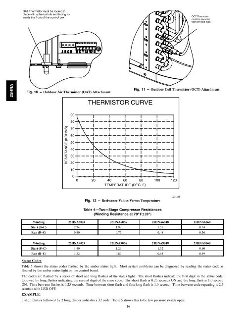
OAT Thermistor must be locked inplace with spherical nib end facing towardsthe front of the control boxOCT Thermistormust be securedtight on stub tube.25HNAFig. 10 --- Outdoor Air Thermistor (OAT) AttachmentTHERMISTOR CURVEFig. 11 --- Outdoor Coil Thermistor (OCT) Attachment9080RESISTANCE (KOHMS)7060504030201000 20 40 60 80 100 120TEMPERATURE (DEG. F)Fig. 12 --- Resistance Values Versus TemperatureA91431Table 4—Two---Stage Compressor Resistances(Winding Resistance at 70_F±20_)Winding 25HNA6024 25HNA6036 25HNA6048 25HNA6060Start (S-C) 2.74 1.98 1.55 0.74Run (R-C) 0.80 0.75 0.48 0.36Winding 25HNA9024 25HNA9036 25HNA9048 25HNA9060Start (S-C) 1.40 1.29 1.52 0.60Run (R-C) 1.32 0.89 0.64 0.49Status CodesTable 5 shows the status codes flashed by the amber status light. Most system problems can be diagnosed by reading the status code asflashed by the amber status light on the control board.The codes are flashed by a series of short and long flashes of the status light. The short flashes indicate the first digit in the status code,followed by long flashes indicating the second digit of the error code. The short flash is 0.25 seconds ON and the long flash is 1.0 secondON. Time between flashes is 0.25 seconds. Time between short flash and first long flash is 1.0 second. Time between code repeating is 2.5seconds with LED OFF.EXAMPLE:3 short flashes followed by 2 long flashes indicates a 32 code. Table 5 shows this to be low pressure switch open.16


