Directivity and VSWR Measurements - Marki Microwave
Directivity and VSWR Measurements - Marki Microwave
Directivity and VSWR Measurements - Marki Microwave

You also want an ePaper? Increase the reach of your titles
YUMPU automatically turns print PDFs into web optimized ePapers that Google loves.
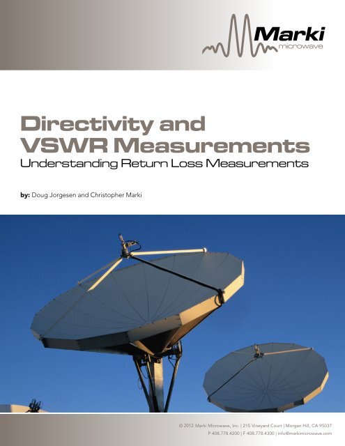
<strong>Marki</strong>microwaveMixer <strong>Directivity</strong> Basics <strong>and</strong>PrimerA<strong>VSWR</strong>Tutorial for RF<strong>Measurements</strong>& <strong>Microwave</strong> MixersUnderst<strong>and</strong>ing Return Loss <strong>Measurements</strong>by: Ferenc <strong>Marki</strong> & Christopher <strong>Marki</strong>, Ph.D.by: Doug Jorgesen <strong>and</strong> Christopher <strong>Marki</strong>© 20122010 <strong>Marki</strong> <strong>Microwave</strong>, Inc. | 215 Vineyard Court | Morgan Hill, CA 95037P 408.778.4200 | F 408.778.4300 | info@markimicrowave.com
Detector(a)DetectorLoadZ = Z 03CoupledForward <strong>and</strong>Leaked ReverseWaves Add withArbitrary PhaseLoadZ = ???VSource132Forward Power MeasurementLoad(Impedance Mismatch)2(b)DetectorForwardSignalReflectedSignalFigure 2: Schematic of a through line power measurement into an unknownimpedance. Finite directivity causes the reflected wave to contaminatethe coupled signal.VSource2Reflected Power Measurement31Load(Impedance Mismatch)in the forward power measurement. This is a fundamentallimitation for ‘in situ’ power measurements 3 .As we show in this paper, choosing a high quality, highdirectivity coupler is crucial to measuring RF power travelingdown a transmission line. We derive expressions to predicterror in forward <strong>and</strong> reverse power measurements, <strong>and</strong> giverules of thumb to limit the measurement error. As a generaltrend, we show that forward power measurements are lesssensitive than reverse power measurements to couplerdirectivity.(c)VSource2DetectorDetector<strong>VSWR</strong>/Return Loss Measurement31Load(Impedance Mismatch)Figure 3: Operation of a directional detector measuring (a) forward power,(b) reverse power, <strong>and</strong> (c) <strong>VSWR</strong>/return loss. The large blue arrow representsinput power, the black arrow is the power we wish to measure,<strong>and</strong> the red arrow represents the interfering term due to finite directivity.Forward Power MeasurementIn forward power measurements (Fig. 3a), the powerdetected at the coupled port is the sum of two waves: thedesired forward coupled wave <strong>and</strong> the undesired reversereflected wave coming from the DUT (as shown in Fig.2). From interference theory, when two waves with thesame frequency combine, the resultant wave is the vectoraddition of the voltages. This means that a small reflectedwave can have a significant <strong>and</strong> variable impact on themeasured power depending on the phase rotation in thereflection.Using the definition of directivity <strong>and</strong> vector voltageaddition, we can show that the upper <strong>and</strong> lower boundpower error for a forward power measurement is given byP eF = 10 · log 10 (10 −IL−RL−D10 +1± 2 · 10 −IL−RL−D20P eF = 10 · log 10 (10 −IL−RL−D10 +1± 2 · 10 −IL−RL−D20 )(3)where P eFis the power error, IL <strong>and</strong> RL are the positivedefined insertion <strong>and</strong> return losses of the device in dB, <strong>and</strong>D is the directivity defined in (2). This is illustrated in Fig. 4,where high <strong>and</strong> low power measurement errors for a devicewith a 1 dB insertion loss are shown for various load returnlosses.3The forward coupled <strong>and</strong> reverse isolated waves add as voltage vectors with unknown phase. Vector network analyzers (VNAs) use the phase informationof the detected signals, combined with calibration routines, to correct for reflections <strong>and</strong> imperfections in the measurement equipment. In thispaper we are concerned with scalar, <strong>and</strong> thus uncorrected measurements only.© 2012 2010 <strong>Marki</strong> <strong>Microwave</strong>, Inc. | 215 Vineyard Court | Morgan Hill, CA 95037P 408.778.4200 | F 408.778.4300 | info@markimicrowave.com<strong>Marki</strong>microwave
This plot shows that- Reflected power will cause significant power errors when anon-directional device is used.- The measured power can fall anywhere within a largerange, depending on the phase of the P eR reflected = RL + signal IL + 10 · log 10 (10 −IL−RL10 + 10 −D10−IL−RL−D± 2 · 10- A device with a directivity of 15 dB or better will generallyreduce forward power measurement errors below 1 dB.A directional device should, therefore, have a directivityof at least 15 dB to make it suitable for forward powermeasurements.Measurement Error (dB)420-2-4Forward Power Measurement Errors-60 10 20 30<strong>Directivity</strong> (dB)DUT Return Loss5 dB10 dB15 dB20 dB25 dB30 dBFigure 4: Error in forward power measurement as a function of directivityfor various load return loss values.Reflected Power MeasurementThe challenge in reflected power measurements is that thecoupler must distinguish between a high forward powersignal <strong>and</strong> a much lower reflected power signal (Fig. 3b). Incontrast to forward power measurements, a smaller reflectedpower will require more directivity to achieve the samemeasurement certainty. Reflected power measurementsrequire significantly more coupler directivity than forwardpower measurements to prevent large measurement errors.As derived in the Appendix, the maximum <strong>and</strong> minimumreflected power measurement errors are given byThe measurement error versus DUT return loss is shown inFig. 5, again for a device with a 1 dB insertion loss.Measurement Error (dB)1050-5-10-15-20P eR = RL + IL + 10 · log 10 (10 −IL−RL10 + 10 −D10 ± 2 ·Reflected Power Measurement Errorsfor Various Load Return Loss ValuesDUT Return Loss5 dB10 dB15 dB20 dB25 dB30 dB20 )0 10 20 3040(4)<strong>Directivity</strong> (dB)Figure 5: Error in reflected power measurement as a function of directivity.From this plot we see- Reflected power measurements are dramatically moresensitive to measurement device directivity than forwardpower measurements- When the directivity (minus insertion loss) is equal to thereturn loss, the leaked forward signal will be equal to thedesired coupled reflected signal, resulting in a potentiallycomplete cancellation <strong>and</strong> infinite error- A directivity of ~15 dB better than the DUT return loss isnecessary to reduce errors to the order of ~1 dB. A directivityof ~5 dB better than DUT return loss will result in errors of~5 dB.Thus to accurately measure reflected power from a loadwith a return loss of less than -15 dB, a directivity of 30 dB orbetter is required. This is significantly higher than the 15-20dB typical directivity of most couplers <strong>and</strong> requires a highdirectivity measurement device.© 2012 2010 <strong>Marki</strong> <strong>Microwave</strong>, Inc. | 215 Vineyard Court | Morgan Hill, CA 95037P 408.778.4200 | F 408.778.4300 | info@markimicrowave.com<strong>Marki</strong>microwave
Measurement ConsiderationsDirectional Bridge vs. Directional CouplerA directional coupler, as described at the beginning of thispaper (Figs. 1, 8a), uses a coupled line with wave cancellationto make directional power measurements. A directionalbridge is a directional device similar to a directional coupler(Fig. 8b). The directional bridge uses a Wheatstone bridgestructure with broadb<strong>and</strong> baluns to achieve significantlyhigher directivity <strong>and</strong> a broader b<strong>and</strong>width (lower cutofffrequency) than directional couplers. The tradeoff toachieving multi-decade b<strong>and</strong>width is insertion loss.(a)3 41 2Directional CouplerStripline bidirectional couplers use proximity coupling toprovide moderate levels of directivity (15-25 dB) acrossseveral octaves up to very high (65 GHz) frequencies. Theyhave lower insertion loss <strong>and</strong> offer both a through <strong>and</strong>reflected coupled port.For high power <strong>and</strong> low loss applications, airline couplersoffer comparable directivities (15-25 dB) but with a lossless than 0.5 dB <strong>and</strong> power h<strong>and</strong>ling up to 200 W on someunits. The tradeoff is a non-flat coupling ratio, which mustbe calibrated out.Unidirectional vs. Bidirectional vs. Dual Directional CouplersDirectional couplers are bidirectional. A bidirectionalcoupler can be used to measure both forward <strong>and</strong> reversepower simultaneously if both coupled ports are terminatedin broadb<strong>and</strong> 50 Ω detectors. Unfortunately, any detectorload mismatch will cause errors in the power reading on theother port. Therefore, many directional couplers include a50 Ω termination internally to make a three port device.(b)350Ω50Ω1 2Directional BridgeFigure 8: Operation of a directional coupler vs. directional bridge.<strong>Marki</strong> directional bridges use a Wheatstone bridge circuitto achieve extremely high levels of directivity (30-40 dB)down to kHz frequencies. Since the Wheatstone bridge is aresistive circuit, there is extra insertion loss in a directionalbridge. For example, a Wheatstone bridge tuned to have a16 dB coupling will have a 1.6 dB nominal insertion loss 5 .Therefore, one can expect between 2 <strong>and</strong> 3 dB of totalinsertion loss in a 16 dB directional bridge when accountingfor excess losses caused by material <strong>and</strong> conductor loss.Furthermore, since most of the power is dissipated in theresistors, directional bridges cannot typically h<strong>and</strong>le morethan ≈ 1 Watt of input power. With directivities better than30 dB from 200 kHz to more than 10 GHz, the directionalbridge is indispensable for broadb<strong>and</strong> measurements <strong>and</strong>significantly simplifies test setups.Bidirectional CouplerDual Directional CouplerFigure 9: Operation of a bidirectional coupler vs. a dual directional cou-A dual directional coupler minimizes the influence ofdetector mismatch in <strong>VSWR</strong> measurements (Fig. 9).Return Loss Measurement ExampleTo underst<strong>and</strong> the tradeoffs in selecting a directional device,it is instructive to consider the sources of error that mightbe present in an actual return loss measurement. As anexample we’ll measure the return loss of a 10 dB attenuatorVP INC IL P RRLReturn Loss MeasurementFigure 10: Schematic of the example return loss measurement.10 dB5Dunsmore, J., “Network Analyzer Basics”, as presented to UC Berkeley EECS 142, 2007.© 2010 2012 <strong>Marki</strong> <strong>Microwave</strong>, Inc. | 215 Vineyard Court | Morgan Hill, CA 95037P 408.778.4200 | F 408.778.4300 | info@markimicrowave.com<strong>Marki</strong>microwave
terminated in an open circuit (Fig. 10). Assuming the opencircuit is broadb<strong>and</strong>, the return loss of this device should be20 dB.Device<strong>Directivity</strong>(dB)InsertionLoss (dB)CalculatedHighError (dB)CalculatedLowError (dB)MeasuredReturnLoss (dB)MeasuredReturn LossError (dB)CompetitorDirectionalCoupler19.30.26.5-19.214.06.0AirlineCoupler23.00.14.7-10.917.52.5DirectionalCoupler30.10.52.4-3.320.9-0.9DirectionalBridge37.31.91.4-1.619.30.7Table 1: Measured return loss values <strong>and</strong> error values using different measurementdevices.ConclusionThe most reliable <strong>and</strong> convenient method for makinguncorrected return loss measurements is to use a wellmatched directional device. The directivity <strong>and</strong> return lossof the directional device determines the accuracy of thereturn loss measurement. <strong>Marki</strong> <strong>Microwave</strong> has a varietyof directional devices including high directivity broadb<strong>and</strong>directional bridges, directional <strong>and</strong> dual directional couplers,<strong>and</strong> airline directional couplers to suit any measurementapplication.© 2010 2012 <strong>Marki</strong> <strong>Microwave</strong>, Inc. | 215 Vineyard Court | Morgan Hill, CA 95037P 408.778.4200 | F 408.778.4300 | info@markimicrowave.com<strong>Marki</strong>microwave
Appendix: Derivations <strong>and</strong> CalculationsForward Power Measurementwhich, after vector addition, gives a measured power ofP mR = P 0 − C + 10 · log 10 (10 −IL−RL10 + 10 −D10 +2· 1P mR = P 0 − C + 10 · log 10 (10 −IL−RL10 + 10 −D−IL−RL−DIn this case the powers are given by10 +2· 10 20 cosθ)P F = P 0 − CP R = P 0 − IL − RL − C − Dwhere P Fis the forward coupled power, P 0is the inputpower, C is the coupling ratio, P Ris the reflected power thatleaks into the coupled port, IL is the device insertion loss, RLis the return loss at the impedance discontinuity, <strong>and</strong> D isthe directivity of (2), with all parameters defined as positive<strong>and</strong> in dB or dBm as appropriate. The power measured atthe coupled port is calculated as the vector addition of thetwo voltages{Z · 10 P 0 −CV m =(V m ={Z · 10 P 0 −C( )10 −IL−RL−D10 +1+2·}·10 −IL−RL−D20 cosθ)+1+2·}10 −IL−RL−D1010 −IL−RL−D10{Z · 10 P 0 −CV m =()+1+2·}where θ is the phase angle between the forward <strong>and</strong>reflected waves at the coupled port determined by thephase length to the reflection point. The power in dBmmeasured from this voltage will then beFor a reflected power measurement the desired coupledreflected power <strong>and</strong> undesired coupled forward power aregiven by)1/2P R = P 0 − IL − RL − C − DP R = P 0 − IL P F −= RL P 0 − C − D(7)(8)In this case the desired power is P 0-IL – RL – C, so the powererror can be found by dividing (subtracting in dB) this fromthe measured power to leave a formula in terms of IL, RL,<strong>and</strong> D.P eR = RL + IL + 10 · log 10 (10 −IL−RL10 + 10 −D10 +2P eR = RL + IL + 10 · log 10 (10 −IL−RL10 + 10 −D−IL−RL−D10 +2· 10 20 cosθ)(9)<strong>VSWR</strong>/Return Loss MeasurementThe return loss of a load is defined as the amount of powerpresented at the port that is reflected back to the source.If a bidirectional or dual directional coupler with reciprocaldirectivity is used to measure it, the return loss will becalculated as the reflected power divided by the couplingpower multiplied by the insertion loss. In dB it is given byRL = P mF + IL − P mRwhich, plugging in our previously calculated forward <strong>and</strong>reverse powers, givesP mF = P 0 − C + 10 · log 10 (10 −IL−RL−D10 +1+2· 10 −IL−RL−D20 cosθ)RL m = IL + 10 · log 10 (10 −IL−RLg 10 (10 −IL−RL−D10 +1+2· 10 −IL−RL−D10 + 10 −D10 +220 cosθ) (10) log 10 (10 −IL−RL−D10 +1+2· 10 −IL−RL−D20 cosθ)RL m = IL + 10 · log 10 (10 −IL−RL10 + 10 −D10 +2· 10 −IL−RL−D20RL cosθ) − 10 ·Reflected Power log Measurement10 (10 −IL−RL−D10 +1+2· 10 −IL−RL−Dm = IL + 10 · log 10 (10 −IL−R1020 cosθ) log 10 (10 −IL−RL−D+1+2· 10 −IL−RL−20RL m = IL + 10 · log 10 (10 −IL−RL10 + 10 −D10 +2· 1log 10 (10 −IL−RL−D10 +1+2· 10 −IL−RL−D20 cosθ)(11)(12)(13)(14)(15)(16)When the directivity goes to infinity, this formula reducesto the return loss. It is also apparent that for large valuesof IL, RL, or D the final term will be very close to zero <strong>and</strong>the return loss will be dominated by the error in reflectedpower measurement.<strong>Marki</strong> <strong>Microwave</strong>215 Vineyard Ct.Morgan Hill, CA 95037408-778-4200 (ph.)408-778-4300 (fax)info@markimicrowave.com© 2010 2012 <strong>Marki</strong> <strong>Microwave</strong>, Inc. | 215 Vineyard Court | Morgan Hill, CA 95037P 408.778.4200 | F 408.778.4300 | info@markimicrowave.com<strong>Marki</strong>microwave