Directivity and VSWR Measurements - Marki Microwave
Directivity and VSWR Measurements - Marki Microwave
Directivity and VSWR Measurements - Marki Microwave

You also want an ePaper? Increase the reach of your titles
YUMPU automatically turns print PDFs into web optimized ePapers that Google loves.
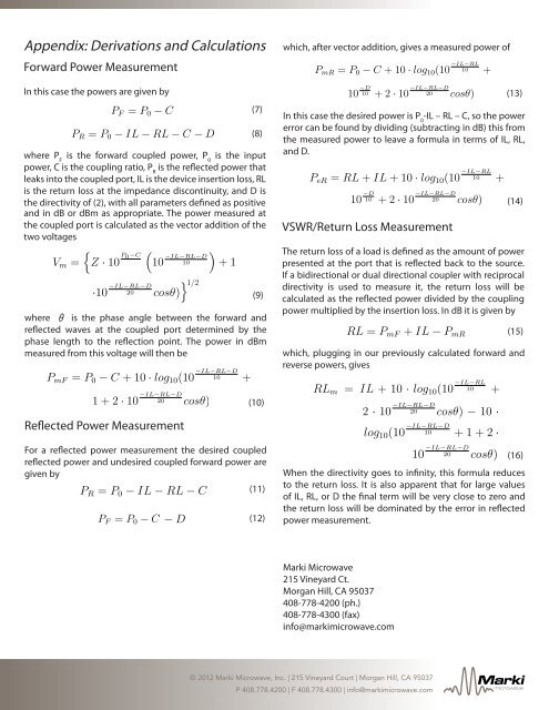
Appendix: Derivations <strong>and</strong> CalculationsForward Power Measurementwhich, after vector addition, gives a measured power ofP mR = P 0 − C + 10 · log 10 (10 −IL−RL10 + 10 −D10 +2· 1P mR = P 0 − C + 10 · log 10 (10 −IL−RL10 + 10 −D−IL−RL−DIn this case the powers are given by10 +2· 10 20 cosθ)P F = P 0 − CP R = P 0 − IL − RL − C − Dwhere P Fis the forward coupled power, P 0is the inputpower, C is the coupling ratio, P Ris the reflected power thatleaks into the coupled port, IL is the device insertion loss, RLis the return loss at the impedance discontinuity, <strong>and</strong> D isthe directivity of (2), with all parameters defined as positive<strong>and</strong> in dB or dBm as appropriate. The power measured atthe coupled port is calculated as the vector addition of thetwo voltages{Z · 10 P 0 −CV m =(V m ={Z · 10 P 0 −C( )10 −IL−RL−D10 +1+2·}·10 −IL−RL−D20 cosθ)+1+2·}10 −IL−RL−D1010 −IL−RL−D10{Z · 10 P 0 −CV m =()+1+2·}where θ is the phase angle between the forward <strong>and</strong>reflected waves at the coupled port determined by thephase length to the reflection point. The power in dBmmeasured from this voltage will then beFor a reflected power measurement the desired coupledreflected power <strong>and</strong> undesired coupled forward power aregiven by)1/2P R = P 0 − IL − RL − C − DP R = P 0 − IL P F −= RL P 0 − C − D(7)(8)In this case the desired power is P 0-IL – RL – C, so the powererror can be found by dividing (subtracting in dB) this fromthe measured power to leave a formula in terms of IL, RL,<strong>and</strong> D.P eR = RL + IL + 10 · log 10 (10 −IL−RL10 + 10 −D10 +2P eR = RL + IL + 10 · log 10 (10 −IL−RL10 + 10 −D−IL−RL−D10 +2· 10 20 cosθ)(9)<strong>VSWR</strong>/Return Loss MeasurementThe return loss of a load is defined as the amount of powerpresented at the port that is reflected back to the source.If a bidirectional or dual directional coupler with reciprocaldirectivity is used to measure it, the return loss will becalculated as the reflected power divided by the couplingpower multiplied by the insertion loss. In dB it is given byRL = P mF + IL − P mRwhich, plugging in our previously calculated forward <strong>and</strong>reverse powers, givesP mF = P 0 − C + 10 · log 10 (10 −IL−RL−D10 +1+2· 10 −IL−RL−D20 cosθ)RL m = IL + 10 · log 10 (10 −IL−RLg 10 (10 −IL−RL−D10 +1+2· 10 −IL−RL−D10 + 10 −D10 +220 cosθ) (10) log 10 (10 −IL−RL−D10 +1+2· 10 −IL−RL−D20 cosθ)RL m = IL + 10 · log 10 (10 −IL−RL10 + 10 −D10 +2· 10 −IL−RL−D20RL cosθ) − 10 ·Reflected Power log Measurement10 (10 −IL−RL−D10 +1+2· 10 −IL−RL−Dm = IL + 10 · log 10 (10 −IL−R1020 cosθ) log 10 (10 −IL−RL−D+1+2· 10 −IL−RL−20RL m = IL + 10 · log 10 (10 −IL−RL10 + 10 −D10 +2· 1log 10 (10 −IL−RL−D10 +1+2· 10 −IL−RL−D20 cosθ)(11)(12)(13)(14)(15)(16)When the directivity goes to infinity, this formula reducesto the return loss. It is also apparent that for large valuesof IL, RL, or D the final term will be very close to zero <strong>and</strong>the return loss will be dominated by the error in reflectedpower measurement.<strong>Marki</strong> <strong>Microwave</strong>215 Vineyard Ct.Morgan Hill, CA 95037408-778-4200 (ph.)408-778-4300 (fax)info@markimicrowave.com© 2010 2012 <strong>Marki</strong> <strong>Microwave</strong>, Inc. | 215 Vineyard Court | Morgan Hill, CA 95037P 408.778.4200 | F 408.778.4300 | info@markimicrowave.com<strong>Marki</strong>microwave