Manual - Atlas International
Manual - Atlas International
Manual - Atlas International

You also want an ePaper? Increase the reach of your titles
YUMPU automatically turns print PDFs into web optimized ePapers that Google loves.
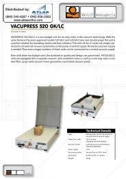
Vacupress Apparatebauund technisches ZubehörPeter WitzelMax Keith Str. 66 - 45136EssenTel. 0201 / 6462-284 - Fax: 0201 / 6462-852info@vacupress.de / www.vacupress.de<strong>Manual</strong>Operations and maintenanceVACUPRESS 520 GK-LC / LCDThis manual is an integral part of the installation and must behanded over to a new owner in case of sale or to an operator incase of use by a third party!Version 2005-01 (C)
IndexpageAttention 41 Summary 41.1 Short description of the unit 41.2 Technical Details 41.3 Purpose of the VACUPRESS unit 51.4 <strong>Manual</strong> 51.5 Definitions 52 Safety instructions 72.1 Reading of the manual 72.2 Vacuum-connection 72.3 Notice – of hazard while operation 72.3.1 - for the working frame 72.3.2 - for the rubber 82.3.3 - for using solvent 83 Description of function 93.1 Main handle 93.2 Vacuum tap 93.3 Venting tap 93.4 Air filter 94 Operation instructions 104.1 Insert the rubber 104.2 Insert the material to be formed 114.3 Removal of the molded material 115 Maintenance 125.1 Air filter 125.1.1 Replacement of the Air filter 122
Index (continuation)page6 Repair 136.1 Spare parts 137 Outline of control elements 147.1 Overview 147.2 Details 157.3 Internal elements 158 Declaration of Conformity 163
1 Summary1.1 Short description of the unitVACUPRESS type 520 GK has been developed as a powerful tool to formplastic, leather and other materials over complicated models. This formingtechnique, called deep-drawing or molding, is used mainly in the orthopedicmanufacturing to copy human limbs. VACUPRESS uses a bench on which themodel is fixed. The (thermoplastic) material is laid over the model and on it ahigh flexible working membrane (rubber) is pressed. The rubber is stretched ina frame which will be lowered around the model down to the bench. A vacuumpumpis used to evacuate the air beneath the membrane. The atmosphericpressure presses the membrane onto the material (and on the model) with highforce. The material will be formed truly according to the model.4
1.2 Technical DetailsType:Manufacturer:Working area:Height:Width:Depth:Frame size :Weight:VACUPRESS 520 GK-LCVacuum-deep-drawing unitfor the orthopedic shoe technique, table unitPeter Witzel VACUPRESS ApparatebauMax Keith Str. 66, D-45136 Essenapprox. 0,20 qm200 mm400 mm670 mm520 x 300 mm20 kg5
1.3 Purpose of the VACUPRESS 520 GK unitThe use of the VACUPRESS 520 GK unit is restricted to the following purpose:1. Molding works with pre-heated plastics under the working membrane.2. Molding thermoplastic sheets, pre-heated outside the unit, e.g. in anoven.3. Pressing of other materials e.g. leather or cork, cold or pre-heated,under the working membrane. Never use solvent here!All other applications are not allowed!6
1.4 <strong>Manual</strong>This manual· Describes the elements of the unit· Explains the procedures of the process· Gives the craft reliable instructions for the use of the unit· Draws the attention to the working risks· And gives hints for maintenance and repair1.5 Definitions(see also drawings and pictures on the last pages)main switch:push button (red):limit switch:working frame:working plate:venting tap:main handle:Switch to turn ON and OFF the unit (a)Push button to break the vacuum while opening theworking frame (only type GK I) (c )limit switch (e), which is actuated when the working frameis closed. Through the actuation (GK I) the integratedmagnetic-valve is opened, resp. the integrated vacuumpumpis turned on (GK II)frame (d) into which the working membrane is fixedupper surface (g) of the VACUPRESS bench. On thisplate the model is fixed. Beneath the plate there are-electrical controls-vacuum-pump (GK II)-venting taptap inside the unit with an outside handle (f) to control theinlet of air to the working membrane and to release themembrane at the end of the working process.handle (b) to fix the working frame in its closed position7
air filter:vacuum-controllerair filter (h) upstream the vacuum-pumpvacuum-controller (i) to control the suction pressure onthe suction side of the vacuum-pump. Below –0.8 bar thepump stops, above –0.6 bar the pump is switched on (onlytype GK II).working membrane: High flexible membrane (rubber) (j) which directs theatmospheric pressure to all sides of the model. Preferableconsisting of rubber.gas spring:vacuum-Pump:magnetic-valve:bolt:frame sealing:The gas spring (k) prevents the working frame from fallingdown in its open position.The Vacuum-Pump (m) (only type GK II) supplies vacuumto the unit. It is controlled by the vacuum-controller (i).The magnetic-valve (n) controls (open-close) the volumeflow of the vacuum.The Bolts (o) are on the top of the working frame. Theworking membrane is mounted with them. If the workingframe is closed the working membrane is additionalclamped by the pressure between working plate andworking frame.The Frame sealing (p) is mounted on the lower surface ofthe working frame and serves to compensate roughnessbetween working frame and working plate.8
2 Safety instructionsThese safety instructions have to be followed before each installationand commissioning.2.1 Reading of this manualPlease read this manual before connecting the VACUPRESS unit to anelectrical source or before commissioning!This manual describes for example risks which exist in connection withimproper use.Take care that each operator of the unit is familiar with this manual.Pay attention that this manual will always be available close to the unit.This manual is an integral part of the installation. It must be handed over to anew owner or operator in case of sale etc.2.3 Possible hazards during operation2.3.1 Working frameRisk of contusion exists for extremities during lifting and loweringof the working frame as well during opening and closing of the fixing frame.Attention – Danger of contusion!2.3.2 Working membraneBursting of the working membrane may lead to a hearing defect.Danger of burst exists using the working membrane for tall models. This goeswith a loud bang.It is recommended to wear ear protection.This is also recommended for other persons working close to the installation.Attention – High noise level possible !Wear ear protection!9
2.3.3 SolventsDanger of explosion exists using solvents. Do not use solvents (forexample acetone, spirit, gasoline, paint dilution etc.) during molding.Solvents can produce explosive mixtures within the unit.Attention – Danger of explosion!10
3 Description of function3.1 Main handle (e)The main handle fixes the working frame in its closed position.3.2 Vacuum tap (c)After closing the frame at the beginning of the deep-drawing process theexternal vacuum can be opened with the vacuum-tap (c):3.3 Venting tap (d)The venting tap (d) has two tasks:· During a molding process it allows to inject air to slow down the suction ofair from the model. Open the vent partly (lever to the left side) to inject air.· At the end of the molding process air is led under the model to release theworking membrane. The air enters with the vent handle in the position“OPEN”.· Be aware that the vent (d) has been closed before the start of the moldingprocess. Position “CLOSED”, lever upwards.3.4 Air filter (g)The vacuum pump evacuates the air between working membrane and workingplate. An air filter on the suction side avoids the entering of dust particles intothe vacuum pump. Decreasing suction efficiency indicates clogging of the airfilter (see point 5.2 Maintenance).11
4 Operation instructionsThese instructions describe the operation procedure in a step by step manner.Legend:· A figure (i.e. .1) is used to instruct an action (e.g. step 4.1.1)· A star + is used to instruct a check. The indicated condition must bepresent before the start of the next action· A hyphen – is used to indicate a consequence or a result of the orderedstep.4.1 Fixing of the working membrane* No model on the working plate.1 remove the old working membrane from the upper bolts (o) on the top ofthe working frame..2 Put the new working membrane on the upper bolts (o). The workingmembrane has be under the working frame, so that it will be clampedbetween the working frame an the working plate by closing the frame.For easier mounting you should fasten the single fixing points crossover..3 Changing of the working membrane is finished when all fixing points aremounted again. Now you can use your VACUPRESS 520 GK again.Attention – Danger of contusion!12
4.2 Insert the material to be formed*The working frame is in the upper position.*A working membrane is fixed in the working frame..1 Turn main switch (a) to ON.2 Move handle of venting tap (f) into position CLOSED..3 Place model on the working table. Be aware of central position..4 Place the material to be formed on to the model and fix it, if necessary..5 Close the working frame and fix it by use of the main handle.- The working membrane is lowered, the working frame contacts thetable. The vacuum pump starts, the vacuum is controlledautomatically.Advice:To achieve a plaster-cast which surrounds the model completely the modelhas to be positioned on a small support. So the foil can follow the contourseven to the underside of the model4.3 Removal of the molded material.1 Close the vacuum-tap ( c).2 Open Venting tap (d) – Air flows under the working membrane. Itdisengages from the model and the working plate. At type GK I the redbutton should be pushed to break the vacuum flow and speed upopening the frame..2 Open main handle (e) and open working frame. The finished model canbe removed.13
5 Maintenance5.1 Air filter (g)The air filter is mounted inside the machine case. For maintenance open theworking plate by removing the four screws on the left and right side of the case.The replacement of the air filter has to be done on demand, usually once ayear. A dirty air filter is mainly recognized by an decreasing suction capacity ofthe vacuum-pump.5.1.1 Replacement of the air filterThe air filter is integrated in the hose system. For replacement loosen the hoseclamp at each end of the filter. Now you can remove the filter from the hose.Mount the new filter – pay attention to mount it in the same direction like the oldone! Now tighten the hose clamps again, close the working plate and tightenthe four screws.14
6 RepairAll parts of VACUPRESS 520 GK I+II are long life and reliable industrial articles. Theyare liable to a thorough quality assurance in the manufacturing process ofVACUPRESS. Therefore, a regular repair is not scheduled.In case of ordering spare parts the following list gives a clear definition of each part.The list is arranged according to the location of the resp. parts. See sketches.6.1 Spare partsNo. Designation Type520200 Vacuum-tap (c) 1/4 "520201 Venting-tap (d) 1/4 "520202 Vacuum-hose (l) 13 mm (inside)520203 One way valve (f) 1/2 " Delrin520204 Air Filter (g) TF5-FILTER520301 Frame sealing (k) 20x10 mm520303 Main handle (e) DK520304 Bolt (i) M4/M415
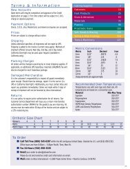
7 Outline of the control elements7.1 Overviewhebcd16
7.2 Detailsfgkia17
8 Declaration of ConformityDeclaration of Conformityfor theDeep Drawing Unit VACUPRESS 520GK-LCPeter Witzel Witzel VACUPRESS ApparatebauMax Keith Str. 66D – 45136 Essendeclares as manufacturer and in sole responsibility that the deep drawing unitVACUPRESS 520GK-LC complies with the requirements of the directive 89/392 EUand the German regulation for the safety of appliances "Gerätesicherheitsgesetz".For further information Peter Witzel Witzel Apparatebau provides the technicaldocumentation:Documents of development and design, description of steps for the declaration ofconformity, analysis of hazards, analysis of the instruction duties and an operationmanual, which complies with the rules for the production of the user information.The Declaration of Conformity for the deep drawing unit VACUPRESS 520GK-LC isguaranteed.Essen, 01.08.2003Peter WitzelVacupress Apparatebau18
VACUPRESSDOESMORE...19