Designing Septic Tanks (USAID) - The Water, Sanitation and Hygiene
Designing Septic Tanks (USAID) - The Water, Sanitation and Hygiene
Designing Septic Tanks (USAID) - The Water, Sanitation and Hygiene

Create successful ePaper yourself
Turn your PDF publications into a flip-book with our unique Google optimized e-Paper software.
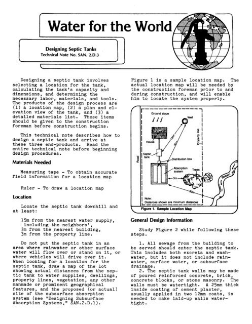
<strong>Water</strong> for the World<strong>Designing</strong> <strong>Septic</strong> <strong>Tanks</strong>Technical Note No. SAN. 2.D.3<strong>Designing</strong> a septic tank involvesselecting a location for the tank,calculating the tank's capacity <strong>and</strong>dimensions, <strong>and</strong> determining thenecessary labor, materials, <strong>and</strong> tools.<strong>The</strong> products of the design process are(1) a location map, (2) a plan <strong>and</strong> elevationview of the tank, <strong>and</strong> (3) adetailed materials list. <strong>The</strong>se itemsshould be given to the constructionforeman before construction begins.Figure 1 Is a sample location map. <strong>The</strong>actual location map will be needed bythe construction foreman prior to <strong>and</strong>during construction, <strong>and</strong> will enablehim to locate the system properly.r ------------I Ground slopeThis technical note describes how todesign a septic tank <strong>and</strong> arrive atthese three end-products. Read theentire technical note before beginningdesign procedures.MaterialsNeededMeasuring tape - To obtain accuratefield Information for a location mapRuler - To draw a location maplocationatLocate the septic tank downhill <strong>and</strong>least:15m from the nearest water supply,including the neighbors',3m from the nearest building,3m from the property line.Do not put the septic tank in anarea where rainwater or other surfacewater will flow over or st<strong>and</strong> on it, orwhere vehicles will drive over it.When looking for a location for theseptic tank, draw a map of the lotshowing actual distances from the septictank to water supplies, dwellings,property lines, vegetation, any othermanmade or prominent geographicalfeatures, <strong>and</strong> the proposed (or actual)site of the subsurface absorptionsystem (see "<strong>Designing</strong> SubsurfaceAbsorption Systems," SAN.2.D.l).GeneralDistances shown are minimum distancesII-------_--J /IFigure 1. Sample Location MapDesign InformationStudy Figure 2 while following thesesteps.1. All sewage from the building tobe served should enter the septic tank.This includes both excreta <strong>and</strong> washwater,but it does not include rainwater,surface water, or subsurfacedrainage.2. <strong>The</strong> septic tank walls may be madeof poured reinforced concrete, brick,concrete blocks, or stone masonry. <strong>The</strong>walls must be watertight. A 25mm thickinside coating of cement plaster,usually applied in two 12mm coats, Isneeded to make laid-up walls watertight.
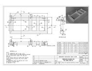
2Top ViewOutsidelength-1TInlet (1 OOmm sewer pipe)Raw sewage fromdwelling,,Effluent toabsorptionsystemSide <strong>and</strong> end walls:100-l 50mm reinforcedconcrete or 200mm brick masonry with 25mminside finish of cement plasterSide View Top:JOOmm reinforced concreteRaw sewage &Inlet 7” exends -into liquid minimum150mm. Maximumis depth of outlet ‘TFigure 2. <strong>Septic</strong> TankFlow line (same elevationT.5c ..‘. -‘; .,:.-.-..:. , ‘..-C-r :,.,.:.e.es::,.. .:.: :’: ‘, >.,:.:‘;‘: ,2.-..::.. .-.._.z:r,:’: 269: ._ +-fi into liquid 360-600mm,....;. a (40% of liquid depth)J sg: . .;.-’ 35..): .:. ::.... . : *‘.: .*.. r. . _ ,., ..,rl*,‘,.. .. y , : :. ‘r: ‘- ‘-., .:: .: : : y.:,: ‘; :.. . .. ,.f .,.... y:.Bottom: lOO-150mm reinforced concreteor 200mm brick masonry with 25mminside finish of cement plasterb Effluent3. <strong>The</strong> floor of the septic tank 5. Predesigned, prefabricated tanksshould be made of reinforced concrete may be available. <strong>The</strong>y are made of100-150mm thick <strong>and</strong> should rest on a fiberglass, precast reinforcedbed of gravel or s<strong>and</strong> 75mm thick.4. <strong>The</strong> tank must have a strong,watertight top, usually made of reinforcedconcrete. <strong>The</strong> top should bedesigned in 300mm wide sections, witheach section as long as the septic tankis wide <strong>and</strong> equipped with a h<strong>and</strong>holdnear each end. One or two sectionsover the outlet end can be removed toinspect the tank. All or most of thesections can be removed to clean thetank.concrete, or steel. <strong>The</strong> most Importantconsideration with these tanks isselecting the proper capacity (see nextpage, "Steps in Design").6. <strong>The</strong> recommended liquid depth Inthe tank is 1.2m, however, it may be asshallow as l.lm or as deep as 1.8m.7. <strong>The</strong> length of the tank is two tothree times its width (see Table 1).
8. <strong>The</strong> bottom of the inlet pipe (thepipe entering the septic tank, not the"T" fitting) Is 300mm below the top ofthe tank. <strong>The</strong> bottom of the outletpipe (the pipe leaving the septic tank,not the rtT" fitting) is 75mm below thebottom of the Inlet pipe, or 375mmbelow the top of the tank (see Figure2).9. <strong>The</strong> Inlet <strong>and</strong> outlet pipes arefitted with open "T" sewer pipe fittings.10. <strong>The</strong> sewer pipe from the source ofsewage to the septic tank <strong>and</strong> from theseptic tank to the subsurface absorptionfield is made of vitrified clay,concrete, special plastic, or othernoncorrosive material, <strong>and</strong> Is usually1OOmm In diameter.11. After the tank has been constructed<strong>and</strong> installed, the space betweenthe septic tank's outside walls<strong>and</strong> the earth sides of the hole shouldbe carefully filled <strong>and</strong> the septic tankshould be covered with dirt to gradelevel or above.Table 1. Suggested <strong>Septic</strong> Tank DimensionsVolumeliters1100150019002800380047005700760095001100013000150001900023000260003000038000Lennth. Width, Liquidinside- insld Ie Depthmeters meters meters1.51.81.82.32.73.43.24.34.45.24.94.95.96.27.37.08.50.70.90.91.11.21.21.51.51.81.81.82.22.22.42.42.42.41.10.91.21.21.21.21.21.21.21.21.51.51.51.51.51.81.8\Steps in DesignRefer to Worksheet A in followingthese steps. This is only a samplethat has been filled out; you will needto prepare one for your use.1. Determine how much sewage willenter the septic tank during each24-hour period (see "Estimating Sewageor Washwater Flows," SAN.2.P.2).2. Determine the desired retentiontime. It should be a minimum of oneday <strong>and</strong> a maximum of three days. Whendetermining retention time, considerthe following:(a) A longer retention timerequires a larger tank, <strong>and</strong> thus ahigher initial cost. However, a largertank needs to be cleaned less oftenthan a smaller one. Larger tanks alsotreat the sewage more, which Increasesthe life of the subsurface absorptionsystem.(b) A shorter retention timerequires a smaller tank, <strong>and</strong> thus reducesthe initial cost.3. Determine the capacity of thetank. Do this by multiplying the dailyflow by the retention time (In days).For example:Suppose that the estimated dailyflow of sewage is 1500 liters, <strong>and</strong>the desired retention time Is 2.5days. <strong>The</strong> tank capacity Is 1500liters a day times 2.5 days: thetank capacity equals 3800 liters.4. Is the type of building thesystem is being designed for a familydwelling or public building? If it Isa family dwelling, go to step 5. If itis a public building, go to step 4a.4a. <strong>Septic</strong> tanks for certain types ofpublic buildings, such as schools,stores, <strong>and</strong> factories, must be largeenough to receive sewage when all ormost of the sewage flow takes placewithin a few hours. For suchbuildings, first determine the normalsize of the septic tank (steps 1, 2,<strong>and</strong> 3). In this example, the flow is3800 liters a day.3
- -
For example, suppose the septic tankhas a capacity of 3800 liters. First,calculate the dimensions of the tank asin Worksheet A. <strong>The</strong>n proceed withsteps (11, (21, (3) above using a formlike Worksheet B for the calculations.This worksheet is only a sample thathas bee.n filled out; you will need toprepare one for your use.1. <strong>The</strong> volume of the top is the outsidelength times the outside widthtimes the thickness. <strong>The</strong> outsidedimensions are used because the topmust span the inside dimensions plusthe thicknesses of the walls.<strong>The</strong> volume of the bottom is thesame as the volume for the top.<strong>The</strong> volume of the two side walls isthe inside length times the insideheight times the thickness times two.<strong>The</strong> volume of the end walls is theinside width times the inside heighttimes the thickness times two.<strong>The</strong> total mixed volume is the sum ofall these volumes, in this example2.lm3.2. Multiply the mixed volume by 1.5to determine the unmixed volume. Inthis example, the unmixed volume is3.15m3.3. Multiply the unmixed volume byeach percentage to find the quantity ofeach material. In this example, thequantities are:cement 0. m3s<strong>and</strong> 0.9, 3gravel 1.4m3water 0.3m3 (300 liters)Reinforcing material. If the reinforcingmaterial is chain-link fencingor wire mesh, the quantity will beapproximately equal to the combinedsurface area of each slab. Add thearea of the top plus the area of thebottom plus the area of the two sidesplus the area of the two ends. <strong>The</strong>area of the top is the outside lengthtimes the outside width; the area ofthe two ends is the inside width timesthe inside height times two (seeWorksheet B).If the reinforcing material is steelbars, sketch each slab (see Figure 41,draw in the bars using the criteriagiven in Figure 4, <strong>and</strong> count the bars.Remember, a separate quantity Is neededfor each length of bar.Top View25mmnEnd ViewFigure 4. Steel Rod Placement in Reinforced Concrete SlabL8
Sewer pipe. <strong>The</strong> pipe must be ofnoncorrosive, durable material such ascast-iron soil pipe, vitrified clay,concrete, bitumlnized fiber, asbestoscement, or plastic. <strong>The</strong> trench linefor the pipe should be as straight aspossible from the dwelling to the septictank <strong>and</strong> from the tank to theabsorption field. Avoid bends. Planthe pipe line so that it falls evenly<strong>and</strong> smoothly from the dwelling to thetank with a slope of from 1 in 50 to 1In 100, <strong>and</strong> from the tank to the fieldwith a slope of 1 in 100. Figure 5shows the slope of these pipes. <strong>The</strong>total length of pipe needed will be thedistance along the trench line from thedwelling to the tank <strong>and</strong> from the tankto the absorption field (see "<strong>Designing</strong>Subsurface Absorption Systems,"SAN.2.D.l). Sewer pipe is generally1OOmm in diameter.When labor requirements, materials,(Including concrete mix, reinforcingmaterials, <strong>and</strong> sewer pipe), <strong>and</strong> toolshave been decided, prepare a materialslist <strong>and</strong> give it to the constructionforeman.ImportantConsiderations1. <strong>The</strong> location of the septic tankis vital. (Review section onlocation.) Provide the constructionforeman with a map similar to Figure 1,showing actual distances from the septictank to dwellings, water supplies,roads, <strong>and</strong> other man-made or prominentfeatures.2. <strong>The</strong> entire system must bedesigned so that sewage moves by gravityflow from the building, throughthe septic tank, <strong>and</strong> to the subsurfaceabsorption system. As Figure 5indicates:(a) <strong>The</strong> septic tank inlet must belower than the sewer line;(b) <strong>The</strong> septic tank outlet must belower than the inlet, usually 75mmlower;(c) <strong>The</strong> distribution box, If thereis one, must be lower than the septictank outlet;(d) <strong>The</strong> subsurface absorptionsystem must be lower than the distributionbox.All of these elevations must bechecked both on a drawing <strong>and</strong> In thefield prior to <strong>and</strong> during construction.(see "<strong>Designing</strong> Subsurface AbsorptionSystems," SAN.2.D.l).Give the construction foreman alocation map <strong>and</strong> plan view of the septictank containing all necessarydimensions <strong>and</strong> a detailed materialslist with quantities of all materialsneeded.lgure 5. Slope <strong>and</strong> Elevation Checkpoints