Himalayan hinterland-verging superstructure folds related to ...
Himalayan hinterland-verging superstructure folds related to ...
Himalayan hinterland-verging superstructure folds related to ...

Create successful ePaper yourself
Turn your PDF publications into a flip-book with our unique Google optimized e-Paper software.
Journal of Structural Geology xxx (2010) 1e14Contents lists available at ScienceDirectJournal of Structural Geologyjournal homepage: www.elsevier.com/locate/jsg<strong>Himalayan</strong> <strong>hinterland</strong>-<strong>verging</strong> <strong>superstructure</strong> <strong>folds</strong> <strong>related</strong> <strong>to</strong> foreland-directedinfrastructure ductile flow: Insights from centrifuge analogue modellingLaurent Godin a, *, Chris Yakymchuk a , Lyal B. Harris ba Department of Geological Sciences and Geological Engineering, Queen’s University, Kings<strong>to</strong>n, Ontario K7L 3N6, Canadab Institut national de la recherche scientifique, centre - Eau Terre Environnement, 490 de la Couronne, Quebec City, Quebec G1K 9A9, CanadaarticleinfoabstractArticle his<strong>to</strong>ry:Received 3 January 2010Received in revised form29 August 2010Accepted 13 September 2010Available online xxxKeywords:Centrifuge analogue modellingChannel flowHimalayaTec<strong>to</strong>nicsDetachment shear zonesThe orogenic <strong>superstructure</strong> (SS) and infrastructure (IS) constitute two levels of a mountain belt withcontrasting structural styles. In the Nepal Himalaya, N-<strong>verging</strong> back <strong>folds</strong>, which oppose the orogenicvergence, dominate the SS. Competing explanations for these <strong>folds</strong> are tested using centrifuge analoguemodels. Modelling suggests that SS folding occurs during bulk shortening accompanied by IS thickeningbefore IS flow. Focused erosion then instigates IS lateral flow and stretching, decoupling of the SS, andtransposition of the lower SS in<strong>to</strong> a detachment zone. Decoupling at the ISeSS interface separates an SSdominated by older <strong>folds</strong> and an IS characterised by younger horizontal transposition and stretching ofearly <strong>folds</strong>. Extrusive ductile flow of the IS locally modifies fold vergence in the SS. The fold asymmetry isthus controlled by the efficiency of coupling between IS and SS; a low viscosity at the ISeSS interfacefavours complete decoupling and hinders modification of fold vergence, whereas a higher viscosity IS-SSinterface favours fold vergence modification. Modelling supports a tec<strong>to</strong>nic scenario in which <strong>Himalayan</strong><strong>hinterland</strong>-<strong>verging</strong> <strong>folds</strong> are the product of early shortening of the SS followed by local modification offold geometry when the IS subsequently stretches and flows during focused erosion and melt-enhancedIS weakening.Ó 2010 Elsevier Ltd. All rights reserved.1. IntroductionContinental crust undergoing regional deformation displayscomplex vertical strain distribution (or zonation) reflecting dominantdeformation processes that vary with depth. The <strong>superstructure</strong> istypically characterised by upright <strong>folds</strong> in low metamorphic-graderocks, indicative of bulk horizontal shortening, whereas the subjacentinfrastructure contains high-metamorphic grade migmatitic rockswith gently-inclined, strongly-transposed features emblematic ofhorizontal stretching and shearing (Wegmann, 1935). The terms“<strong>superstructure</strong>” and “infrastructure” are used here <strong>to</strong> describecrustal-scale differences between the upper crust, which dominantlydeforms by frictional-plastic (Coulomb-type) failure, and theunderlying mid-crust in which the deformation is dominated bypower-law creep. The <strong>superstructure</strong>-infrastructure classificationhas recently been revived in the literature, partly due <strong>to</strong> its similaritieswith and applicability <strong>to</strong> numerical models of continental collisionthat produce mid- <strong>to</strong> lower crustal flow (Beaumont et al., 2001,2006; Culshaw et al., 2006). In such models, the weakened midcrustresponds either <strong>to</strong> the introduction of a lower crustal indenter* Corresponding author. Fax: þ1 613 533 6592.E-mail address: godin@geol.queensu.ca (L. Godin).(Culshaw et al., 2006), or an imposed lithostatic pressure gradientby flowing laterally <strong>to</strong>wards the orogenic front beneath a comparativelypassive orogenic <strong>superstructure</strong> (Beaumont et al., 2001, 2006;Godin et al., 2006a, for review).In this paper, analogue centrifuge models are used <strong>to</strong> investigatecontrasting deformation styles in the <strong>superstructure</strong> and infrastructureobserved in continental collision zones. Models aredesigned <strong>to</strong> simulate the structural evolution of horizontal shorteningin a <strong>superstructure</strong>/infrastructure package, followed byvertical thinning and horizontal stretching and ductile flow of themelt-weakened infrastructure due <strong>to</strong> focused erosion and a lithostaticpressure gradient in a manner akin <strong>to</strong> channel flow. Emphasisin this study is placed on examining: (1) coeval and dynamicallylinked deformation (coupling) between the <strong>superstructure</strong> andinfrastructure; (2) the formation of drag <strong>folds</strong> along the interfacebetween the <strong>superstructure</strong> and infrastructure during infrastructurehorizontal flow; and (3) the effects of varying the slopesteepness of the orogenic <strong>to</strong>pographic front, which drives extrusionof the ductile infrastructure, on the development of deformationfeatures in the <strong>superstructure</strong>. Specifically, centrifuge analoguemodelling is used <strong>to</strong> test whether <strong>hinterland</strong>-<strong>verging</strong> <strong>folds</strong> candevelop above a sub-horizontally stretching foreland-directedductile-flowing infrastructure (e.g. Larson et al., 2010).0191-8141/$ e see front matter Ó 2010 Elsevier Ltd. All rights reserved.doi:10.1016/j.jsg.2010.09.005Please cite this article in press as: Godin, L., et al., <strong>Himalayan</strong> <strong>hinterland</strong>-<strong>verging</strong> <strong>superstructure</strong> <strong>folds</strong> <strong>related</strong> <strong>to</strong> foreland-directed..., Journal ofStructural Geology (2010), doi:10.1016/j.jsg.2010.09.005
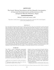
2L. Godin et al. / Journal of Structural Geology xxx (2010) 1e14Our modelling approach, in particular, investigates <strong>hinterland</strong>directed<strong>folds</strong> preserved in the Tethyan sedimentary sequence, the<strong>Himalayan</strong> <strong>superstructure</strong> in central Nepal, where anomalousnorth-<strong>verging</strong> <strong>folds</strong> of unresolved age dominate (Bordet et al., 1971;Godin et al., 1999a; Godin, 2003; Kellett and Godin, 2009). These<strong>folds</strong> are preserved in the hanging wall of a crustal-scale detachment,the South Tibetan detachment system (STDS), below whichthe infrastructure, the Greater <strong>Himalayan</strong> sequence, has beenextensively transposed and metamorphosed (Fig. 1; Grujic et al.,1996; Vannay and Hodges, 1996; Grasemann et al., 1999; Searleand Szulc, 2005; Jessup et al., 2006; Larson and Godin, 2009).2. The <strong>superstructure</strong>-infrastructure association and the<strong>Himalayan</strong> orogen2.1. The <strong>superstructure</strong>-infrastructure conceptA common observation in orogenic belts is the change indominant structural style from upright open <strong>folds</strong> in the <strong>superstructure</strong><strong>to</strong> isoclinal recumbent <strong>folds</strong> in the infrastructure(Murphy, 1987; Godin, 2003; Williams and Jiang, 2005; Culshawet al., 2006; Williams et al., 2006; Denèle et al., 2009; Kellett andGodin, 2009). In this paper, the <strong>superstructure</strong> of an orogenic beltrefers <strong>to</strong> the weakly metamorphosed <strong>to</strong> unmetamorphosed sedimentarysequence resting on the underlying migmatitic infrastructure.The rheology of the <strong>superstructure</strong> renders it mostlysusceptible <strong>to</strong> brittle and brittle-ductile deformation. A crustalscaledetachment, usually marked by a strain gradient across whichrheology and structural styles are often contrasting, separates theinfrastructure from the <strong>superstructure</strong>. The infrastructure refers <strong>to</strong>the ductile, thermally-weakened middle-crust that is of a similardensity and lesser viscosity than the overlying <strong>superstructure</strong>(Mecklenburgh and Rutter, 2003; Rosenberg and Handy, 2005).Examples of such infrastructuree<strong>superstructure</strong> relationships arefound in several orogens, such as the Canadian Cordillera (Murphy,1987; Glombick et al., 2006), the Western Superior Province ofCanada (Culshaw et al., 2006), the French Pyrenees (Denèle et al.,2009), the Oman ophiolitic belt (Searle et al., 2004), and theAustralian Petermann orogen (Raimondo et al., 2009).2.2. The <strong>Himalayan</strong> pro<strong>to</strong>typeThe <strong>Himalayan</strong> orogen is the type example of a large hot orogen,characterised by a viscous mid-crust that contains significant in situpartial melts and where the channel flow process may have beenoperative (Bird, 1991; Grujic et al., 1996, 2002; Royden et al., 1997;Clark and Royden, 2000; Beaumont et al., 2001, 2006).The <strong>Himalayan</strong> orogen initiated in early Eocene times, followingcollision of the Indian and Eurasian plates (see Hodges, 2000 and Yinand Harrison, 2000 for reviews). The convergence culminated inclosure of the Tethyan Ocean, southward imbrication of the Indiancrust, and northward continental subduction of Indian lower crustand lithospheric mantle beneath Asia (Hodges, 2000; Yin andHarrison, 2000). The <strong>Himalayan</strong> orogen consists of five, broadlyparallel lithotec<strong>to</strong>nic belts, separated by mostly north-dipping faults.The Greater <strong>Himalayan</strong> sequence is bounded by two parallel andopposite-sense shear zones that were both broadly active during theMiocene (Fig. 1; Hubbard and Harrison, 1989; Searle and Rex, 1989;Hodges et al., 1992, 1996; chronological review in Godin et al.,2006a). The Main Central thrust (MCT) zone marks the lowerboundary of the Greater <strong>Himalayan</strong> sequence, juxtaposing themetamorphic core above the underlying Lesser <strong>Himalayan</strong> sequence(Searle et al., 2008). The STDS defines the upper boundary roof fault ofthe Greater <strong>Himalayan</strong> sequence, placing it in tec<strong>to</strong>nic contact withthe overlying weakly- <strong>to</strong> unmetamorphosed Tethyan sedimentarysequence (Burg and Chen, 1984; Burchfiel et al., 1992; Searle andGodin, 2003).The apparent coeval movement of the MCT and STDS,combined with the presence of highly sheared rocks and highgrade <strong>to</strong> migmatitic rocks within the Greater <strong>Himalayan</strong>sequence, has led many workers <strong>to</strong> view the metamorphic coreas a north-dipping, southward extruding slab of mid-crustalmaterial flowing away from the thick southern edge of theTibetan Plateau, <strong>to</strong>wards the thinner foreland fold-thrust belt(Grujic et al., 1996, 2002; Law et al., 2004; Searle and Szulc, 2005;Jessup et al., 2006; Godin et al., 2006a; Cottle et al., 2007; Larsonand Godin, 2009; Larson et al., 2010).2.2.1. The <strong>Himalayan</strong> infrastructure: The Greater <strong>Himalayan</strong>sequenceThe Greater <strong>Himalayan</strong> sequence, where exposed at the surface,comprises greenschist <strong>to</strong> granulite facies metamorphic rocks. Thestructural upper half of the Greater <strong>Himalayan</strong> sequence is dominatedby migmatites and discontinuous Miocene leucogranitebodies (Fig. 2). The Greater <strong>Himalayan</strong> sequence is pervasivelytransposed by <strong>to</strong>p-<strong>to</strong>-the-south shear fabrics (Mattauer, 1975;Grujic et al., 1996; Grasemann et al., 1999; Jessup et al., 2006;Larson and Godin, 2009). Microstructural analysis and metamorphicstudies indicate that these ductile fabrics developed atpeak temperatures at ca. 21 Ma, coincident with southwardextrusion (Daniel et al., 2003; Hollister and Grijuc, 2006; Larsonand Godin, 2009; Larson et al., 2010). Vorticity studies yield kinematicvorticity numbers between 0.49 and 0.80 (66% <strong>to</strong> 41% pureshear), with a significant amount of stretch (34e47%) parallel <strong>to</strong> theflow plane (Grasemann et al., 1999; Law et al., 2004; Jessup et al.,Fig. 1. Sketch depicting the <strong>Himalayan</strong> infrastructure and north (<strong>hinterland</strong>)-<strong>verging</strong> <strong>folds</strong> within the <strong>superstructure</strong>. The small half arrows indicate the hanging wall sense ofdisplacement on faults. The small black arrows depict the state of non-coaxial general shear preserved in the <strong>Himalayan</strong> infrastructure (e.g. Larson and Godin, 2009 and referencestherein). The thick black arrow portrays the direction of extrusion of the infrastructure during synchronous motion of its bounding faults; (a) lesser <strong>Himalayan</strong> sequence (LHS), (b)main Central thrust, (c) Greater <strong>Himalayan</strong> sequence (GHS), (d) South Tibetan detachment system, (e) Miocene leucogranites, (f) Tethyan sedimentary sequence (TSS), (g) north<strong>verging</strong><strong>folds</strong>, which are localised in the immediate hanging wall of the South Tibetan detachment system in central Nepal (Godin, 2003; Kellett and Godin, 2009).Please cite this article in press as: Godin, L., et al., <strong>Himalayan</strong> <strong>hinterland</strong>-<strong>verging</strong> <strong>superstructure</strong> <strong>folds</strong> <strong>related</strong> <strong>to</strong> foreland-directed..., Journal ofStructural Geology (2010), doi:10.1016/j.jsg.2010.09.005
L. Godin et al. / Journal of Structural Geology xxx (2010) 1e14 3Fig. 2. (A) Geological map of central Nepal (modified from Colchen et al., 1981; Godin, 2003; Searle et al., 2008; Larson and Godin, 2009; Larson et al., 2010). (B) Cross sectionsdisplaying north-<strong>verging</strong> <strong>folds</strong> preserved in the Tethyan sedimentary sequence (TSS), above the South Tibetan detachment system (STDS) and highly-strained Greater <strong>Himalayan</strong>sequence (GHS). MCT, Main Central thrust. Section AeA 0 : Kellett and Godin, 2009; Section BeB 0 : Godin, 2003; Section CeC 0 : modified from Larson et al. (2010).2006; Carosi et al., 2006, 2007; Larson and Godin, 2009; Larsonet al., 2010). This suggests that the Greater <strong>Himalayan</strong> sequencedeformed by a combination of vertical thinning and horizontalstretching (Larson and Godin, 2009; Larson et al., 2010). Theuppermost w1 km portion of the Greater <strong>Himalayan</strong> sequence ischaracterised by a kinematic reversal in shear-sense that definesthe <strong>to</strong>p-<strong>to</strong>-the-north-sense STDS (Burchfiel et al., 1992; Searle andGodin, 2003).In central Nepal, the Greater <strong>Himalayan</strong> sequence records twoCenozoic thermal pulses associated with <strong>Himalayan</strong> orogenesis:(1) EoceneeOligocene burial metamorphism at ca. 35 Ma, and(2) Miocene peak temperature metamorphism at ca. 21 Ma, coevalwith mid-crustal ductile flow (Hodges, 2000). Structural and40 Ar/ 39 Ar thermochronological data suggest that ductile flow andsouthward extrusion of the Greater <strong>Himalayan</strong> sequence terminatedwith cessation of movement on the brittle upper strand ofPlease cite this article in press as: Godin, L., et al., <strong>Himalayan</strong> <strong>hinterland</strong>-<strong>verging</strong> <strong>superstructure</strong> <strong>folds</strong> <strong>related</strong> <strong>to</strong> foreland-directed..., Journal ofStructural Geology (2010), doi:10.1016/j.jsg.2010.09.005
4L. Godin et al. / Journal of Structural Geology xxx (2010) 1e14the STDS at w19 Ma, which was followed almost immediatelyby <strong>hinterland</strong>-directed out-of-sequence deformation and rapidexhumation, and by activation of new thrusts structurally belowthe Greater <strong>Himalayan</strong> sequence (Godin et al., 2006b; Robinsonet al., 2006; Larson et al., 2010).2.2.2. The <strong>Himalayan</strong> <strong>superstructure</strong>: the Tethyan sedimentarysequenceThe Tethyan sedimentary sequence forms the <strong>superstructure</strong> <strong>to</strong>the Greater <strong>Himalayan</strong> sequence (Fig. 2). In the central NepalHimalaya, the Tethyan sedimentary sequence is a ca. 12 km thickunmetamorphosed <strong>to</strong> weakly metamorphosed Palaeozoic andMesozoic sedimentary sequence, which was deposited on thenorthern Indian palaeocontinental margin and subsequentlydeformed during <strong>Himalayan</strong> orogenesis (Fig. 2b; see Garzanti, 1999for complete stratigraphic framework).In central Nepal, the Palaeozoic section is characterised bymassive limes<strong>to</strong>ne, calcareous shale and pelite, with local dolomiticand quartzitic horizons (Fig. 2a; Bordet et al., 1971; Colchen et al.,1981; Garzanti, 1999). The Mesozoic stratigraphy comprisescalcareous shale, grading upwards <strong>to</strong> limes<strong>to</strong>ne and black shale,which are capped by clastic units (Bordet et al., 1971; Gradsteinet al., 1992).The Tethyan sedimentary sequence has been subjected <strong>to</strong> polyphasedeformation, yet is structurally dominated by north-<strong>verging</strong>back <strong>folds</strong> whose asymmetry is opposite <strong>to</strong> the orogenic vergence(Fig. 2b; Godin et al., 1999a; Godin, 2003). The absolute age of these<strong>folds</strong> is uncertain, although cross-cutting relationships indicate thatthey predate the dominant Miocene motion along the STDS atw21 Ma (Guillot et al., 1993; Godin et al., 1999a, 2001; Kellett andGodin, 2009). Palinspastic bed length res<strong>to</strong>ration of the north<strong>verging</strong><strong>folds</strong> implies a minimum 35% shortening, and a minimum150% vertical thickening (Godin, 2003; Kellett and Godin, 2009).These data suggest that north-<strong>verging</strong> <strong>folds</strong> played a significant role inpre-Miocene crustal thickening (150e180% thickening of 12 kmstratigraphy ¼ approximately 20-km thick) of the <strong>Himalayan</strong> <strong>superstructure</strong>,possibly predating or coinciding with EoceneeOligoceneburial metamorphism (ca. 35 Ma) preserved in the underlyingGreater <strong>Himalayan</strong> sequence (Godin et al., 1999a, 2001; Aikmanet al., 2008).2.2.3. Models for <strong>Himalayan</strong> <strong>superstructure</strong> <strong>hinterland</strong>-directeddeformationCompeting models have been proposed <strong>to</strong> explain the presenceof <strong>hinterland</strong>-<strong>verging</strong> <strong>folds</strong> in the Tethyan sedimentary sequence ofcentral Nepal. Early work suggested that the <strong>folds</strong> were formed bygravity-induced sliding and drag folding coeval with motion alongthe STDS (Fig. 3a; Bordet et al., 1971; Colchen et al., 1981; Burg andChen, 1984; Burchfiel and Royden, 1985; Burchfiel et al., 1992).Others proposed that the north-<strong>verging</strong> <strong>folds</strong> represent features<strong>related</strong> <strong>to</strong> an early compression and crustal-thickening event tha<strong>to</strong>ccurred prior <strong>to</strong> Miocene displacement along the STDS (Fig. 3b;Godin et al., 1999a, 2001). Alternatively, it has been suggested thatthe north-<strong>verging</strong> <strong>folds</strong> may have developed while the STDS wasthe active upper boundary of southward-extruding Greater <strong>Himalayan</strong>sequence rocks; the <strong>folds</strong> recording the opposite shear dragfolding effect of a flowing mid-crustal channel (Fig. 3c; Carosi et al.,2007). More recently, Kellett and Godin (2009) argued that dragowing <strong>to</strong> the southward transport of the mid-crustal Greater<strong>Himalayan</strong> sequence may have modified the geometry of alreadyexisting <strong>folds</strong>, causing the northward vergence of the <strong>folds</strong> in theTethyan sedimentary sequence (Fig. 3d). Previous attempts <strong>to</strong> linksuperstructural features with infrastructural thermal events (e.g.Godin et al., 1999a, 2001; Kellett and Godin, 2009) have beenhindered by a lack of absolute ages for shortening features in theTethyan sedimentary sequence.The centrifuge modelling approach described in the followingsection therefore provides a means <strong>to</strong> test the geometric, kinematic,and dynamic feasibility of these competing folding models for the<strong>Himalayan</strong> <strong>superstructure</strong> and possible genetic links with underlyingductile flow of the infrastructure.3. Experimental approachAnalogue materials with properties scaled <strong>to</strong> represent both thelayered Tethyan sedimentary sequence (the <strong>superstructure</strong>) and theunderlying low-viscosity Greater <strong>Himalayan</strong> sequence (the infrastructure)were used (Tables 1 and 2). The models are deformed ina high-acceleration centrifuge <strong>to</strong> trigger infrastructural horizontalstretching ductile flow. The main goals of experiments are <strong>to</strong>produce superstructural <strong>hinterland</strong>-<strong>verging</strong> <strong>folds</strong> by either:Fig. 3. End-member models for the formation of back-<strong>folds</strong>, modified from Kellett and Godin (2009). Light grey is used <strong>to</strong> indicate deformation that is no longer occurring. Blackindicates active deformation. The darkening gradient portrayed in C and D represents the thermally-weakened middle crust implied in these models. TSS, Tethyan sedimentarysequence; GHS, Greater <strong>Himalayan</strong> sequence; STDS, South Tibetan detachment system; S and L (in A) denote the shortening and lengthening quadrants of the strain ellipse,respectively.Please cite this article in press as: Godin, L., et al., <strong>Himalayan</strong> <strong>hinterland</strong>-<strong>verging</strong> <strong>superstructure</strong> <strong>folds</strong> <strong>related</strong> <strong>to</strong> foreland-directed..., Journal ofStructural Geology (2010), doi:10.1016/j.jsg.2010.09.005
L. Godin et al. / Journal of Structural Geology xxx (2010) 1e14 5Table 1Scaling properties of models and pro<strong>to</strong>type.Quantity Model Pro<strong>to</strong>type Scaling ratioLength ratio 1 mm 1 km l r ¼ l m /l p ¼ 1 10 6Density (bulk) (kg m 3 )Superstructure 1050 a 2700 r r ¼ r m /r p ¼ 0.39Infrastructure 1050 a 2700 r r ¼ r m /r p ¼ 0.39Acceleration 1000 1 a r ¼ 1000Velocity (mm yr 1 ) 2.3 10 6b 59 v r ¼ l r /t r ¼ 3.98 10 4Time 360 s c 0.44 my b t r ¼ m r /l r r r , a r ¼ 2.6 10 11Viscosity (Pa s)Superstructure 1 10 7d 1 10 21 m r ¼ m m /m p ¼ 1 10 14Infrastructure 1 10 5d 1 10 19e m r ¼ m m /m p ¼ 1 10 14a Density varies with the proportion of the different materials in any givensample. On average, both levels are approximately 1050 kg m 3 . The <strong>superstructure</strong>ranges from w990 <strong>to</strong> 1100 kg m 3 , and the infrastructure ranges from w1010 <strong>to</strong>1070 kg m 3 . Densities were calculated with a Grabner Instruments Minidens solidsdensi<strong>to</strong>meter with reproducibility of 10 kg m 3 (w1%).b Calculated for 25 mm shortening each run.c Run-up/down times are not taken in<strong>to</strong> consideration for scaling.d Approximate effective viscosity at experimental strain rates of ca. 5 10 4 s 1 .e Channel flow requires 1 10 19 Pa s in thermo-mechanical models (Jamiesonet al., 2004; Beaumont et al., 2006), but this value is probably lower in nature(Mecklenburgh and Rutter, 2003; Rosenberg and Handy, 2005).(1) horizontal infrastructural flow alone, or (2) modifying the vergenceof already established <strong>folds</strong> by triggering infrastructuralhorizontal flow during the evolution of the system. Finally, variousangles of the foreland <strong>to</strong>pographic front are used <strong>to</strong> obtain insight onthe efficiency of erosion in driving extrusion of the infrastructure.3.1. Centrifuge apparatusA high-acceleration centrifuge is used <strong>to</strong> dynamically scalegravitational forces deemed important <strong>to</strong> the evolution of orogenscalestructures, especially those developed during channel flow(Beaumont et al., 2001, 2006; Godin et al., 2006a). The PR-7000centrifuge at the Institut National de la Recherche Scientifique inQuebec City is capable of subjecting models up <strong>to</strong> 200 mm x 80 mmin plan view <strong>to</strong> accelerations exceeding 1000 g (where g is the localacceleration due <strong>to</strong> gravity). For a detailed explanation of thecentrifuge method, readers are referred <strong>to</strong> Ramberg (1981) andDixon and Summers (1985). Models were run in 6e8 stages, eachfor 360 s at 900 g with a run-up time of 60 s and a run-down time of420 s. In between each stage, vertical sections through the modelsparallel <strong>to</strong> the shortening direction were cut at intervals of w5mmfrom both ends <strong>to</strong> be pho<strong>to</strong>graphed.3.2. Initial model geometry, materials, and scalingInitial model dimensions are 170 mm 80 mm in plan view by20e30 mm in height (Fig. 4a). Where applicable, models were shortenedvia a collapsing wedge 30 mm 80 mm in plan view by 50 mmin height that is placed at the <strong>hinterland</strong> <strong>to</strong> induce layer-parallelshortening based on the method of Dixon and Tirrul (1991).Aweightedplastic plate is inserted between the model and the collapsing wedge <strong>to</strong>provide an equal distribution of force throughout the <strong>hinterland</strong> face ofthe model (Johns and Mosher, 1996). Models consist of a w10-mmthick brittle-ductile <strong>superstructure</strong> overlying a ductile w5-mm thickinfrastructure (Fig. 4b; Table 2). Individual models have slight lateralvariations in layer thickness within the <strong>superstructure</strong>; however, thedynamic effect of this, with respect <strong>to</strong> behaviour of the entire <strong>superstructure</strong>,is interpreted <strong>to</strong> be minimal.Model materials are consistent with materials utilised in publishedcentrifuge studies that simulate different levels of the crustwhere material properties and scaling have been previously discussed(Dixon and Summers, 1985; Dixon and Tirrul, 1991; Koyi,1991; Koyi and Skel<strong>to</strong>n, 2001; Harris and Koyi, 2003; Corti, 2004).The <strong>superstructure</strong> is represented by microlaminates composed ofDemco Ò modelling clay, Dow Corning 3179 dilatant compound (asilicone bouncing putty), and Crayola Model Magic Ò (a low densitymodelling clay), analogous <strong>to</strong> a succession of competent clastics,carbonates and incompetent pelitic and semi-pelitic units (Dixonand Tirrul, 1991) and similar <strong>to</strong> the stratigraphy of the Tethyansedimentary sequence (Garzanti, 1999). A thin layer of low-densityCrayola Model Magic Ò modelling clay is placed at the surface <strong>to</strong>Table 2Model composition.Model/Level Material Thickness (mm)Model 47Cap White Crayola Model Magic a 4Superstructure 7Dow Corning Dilatant compound 3179 0.146Microlaminates of Blue Demco with 40 % Crayola Model Magic 0.146 Package repeated 16 timesBlue Demco with 10% Crayola Model Magic 0.146Infrastructure Layered yellow and red Crazy Aaron with a discontinuous green basal layer 4Model 50Cap White Crayola Model Magic 5Superstructure 10Brown Demco 0.031Blue Demco and 40% Crayola Model Magic 0.208 Package repeated 16 timesOrange Demco and 40% Crayola Model Magic 0.312Infrastructure Layer of Polydimethylsiloxane (half the model) 0.5Layered yellow and green Crazy Aaron putty 6Model 43Cap White Crayola Model Magic 4Superstructure 8Blue Demo mixed with 10% crayola Model Magic 0.1Blue Demco 005Dow Corning Dilatant compound 3179 0.5Package repeated 8 timesBrown Demco mixed with 40% Crayola0.35Model MagicInfrastructure Interlayers of yellow, red, and yellow Crazy Aaron with a discontinuous basal green layer 7a This layer caps all models <strong>to</strong> maintain the structural integrity during deformation and is used instead of a layer simulating upper brittle crust.Please cite this article in press as: Godin, L., et al., <strong>Himalayan</strong> <strong>hinterland</strong>-<strong>verging</strong> <strong>superstructure</strong> <strong>folds</strong> <strong>related</strong> <strong>to</strong> foreland-directed..., Journal ofStructural Geology (2010), doi:10.1016/j.jsg.2010.09.005
6L. Godin et al. / Journal of Structural Geology xxx (2010) 1e14Fig. 5. Compilation of flow properties of Dow Corning 3179 dilatant compound (DC3179; Poulin, 2006), Crazy Aaron Thinking Putty (CATP; Poulin, 2006), and polydimethylsiloxane(PDMS; Weijermars, 1986; ten Grotenhuis et al., 2002).Fig. 4. (A) Model set-up showing the collapsing wedge in the <strong>hinterland</strong> that activateslayer-parallel shortening, similar <strong>to</strong> Dixon and Tirrul (1991). Models consist of a 10 mmthick brittleeductile <strong>superstructure</strong> overlying a 5 mm thick ductile infrastructure. Aweighted nylon plate is inserted between the model and the collapsing wedge <strong>to</strong>provide an equal distribution of force across the <strong>hinterland</strong> face of the model. Theportrayed irregular erosion front was created on some models, while others containedan extra layer of polydimethylsiloxane (PDMS), a clear, low density and viscositypolymer, at the infrastructure-<strong>superstructure</strong> interface. (B) Model composition. Notethat a thin (0.5 mm) layer of PDMS was introduced in some models <strong>to</strong> mimic thepresence of migmatites and leucogranites in the immediate footwall of the SouthTibetan detachment system. All models were covered by a thin layer (1e2 mm) of lowdensityCrayola Model Magic.buffer the density contrast between the uppermost <strong>superstructure</strong>and air (Fig. 4) as no brittle, upper crustal layer was included. Theinfrastructure of the models is composed of Crazy Aaron EnterprisesThinking Putty Ò , a silicone putty (similar <strong>to</strong> Dow Corning RhodorsilGomme Ò whose composition and properties are described byWeijermars, 1986) with scaled densities and viscosities that representductile melt-weakened mid-crust. Effective viscosities ofmaterials at experimental strain rates are presented in Fig. 5. In themodels, the ductile infrastructure has approximately the samedensity (
L. Godin et al. / Journal of Structural Geology xxx (2010) 1e14 7folding; (2) presence or absence of less-viscous ductile layer at thedetachment; and (3) angle of focused erosion front.4.1. Erosion and infrastructure flow below an unfolded layered<strong>superstructure</strong>The goal of this experiment was <strong>to</strong> evaluate if underlying horizontalductile stretching flow (stretching in the direction of flow) ofthe infrastructure could create superstructural <strong>folds</strong>, as suggestedby Carosi et al. (2007) (Fig. 3c). Model 47 (95 mm length) consists ofan undeformed layered <strong>superstructure</strong> resting above a homogeneousinfrastructure (Table 2).An erosion front was cut at the foreland-end of the model beforethe initial run. This was done <strong>to</strong> impose at the onset a lateral lithostaticpressure gradient deemed essential for mid-crustal flow(i.e. channel flow; Beaumont et al., 2001). The erosion front was cutright down <strong>to</strong> the base of the infrastructure, with half the modelhaving a steep w60 e80 front and the other half with a shalloww30 e45 front (and a gentle curved transition between the twoerosion fronts e see Fig. 4). The model was run in seven stages; theerosion front angle was re-cut after each step <strong>to</strong> maintain initialconfiguration. The last two stages of this experiment were run atpeak acceleration (w1100 g) for 15 min with the same run-up anda slightly longer run-down time in an attempt <strong>to</strong> trigger superstructuralfolding.The model behaved similarly with a steep or shallow erosionfront. No deformation was recorded in the <strong>superstructure</strong> in eithercase, whereas significant horizontal stretching and vertical thinningoccurred in the infrastructure (Fig. 6). The <strong>superstructure</strong>microlaminates remain parallel and were not affected by eitherflow-parallel extension or shortening. Although a single erosionfront was maintained, the infrastructure unexpectedly flowed<strong>to</strong>wards the erosion front and the rigid backs<strong>to</strong>p. Despite the factthat the model did not behave as originally envisaged, the resultsshow that at no time during the experiment can the infrastructuralhorizontal flow trigger <strong>superstructure</strong> folding.4.2. Infrastructural flow below already established <strong>superstructure</strong><strong>folds</strong> e the influence of detachment ductilityThe second experiment (Model 50) was run <strong>to</strong> assess theinfluence of the ductility of the detachment on the potential forsuperstructural fold geometry modification (Fig. 7). In this model,a 0.5-mm thick layer of Polydimethylsiloxane (PDMS), simulatingmigmatites and melt pooling in the upper part of the infrastructure,is incorporated on half the <strong>superstructure</strong>-infrastructureinterface <strong>to</strong> investigate its effects on <strong>superstructure</strong> foldgeometry and <strong>superstructure</strong>-infrastructure decoupling efficiency(Table 2).The model underwent two stages of shortening withouterosion (31% of <strong>to</strong>tal shortening), followed by four stages duringwhich the erosion front was created and then maintained at 40 dip (Fig. 7). The erosion front was cut down <strong>to</strong> the base of theinfrastructure.Fig. 6. Sequential pho<strong>to</strong>graphs of Model 47. In this experiment, an erosion front cutting down <strong>to</strong> the base of the infrastructure was created during the first model run (left side) <strong>to</strong>generate a dominant foreland-directed horizontal infrastructural flow. Half the model had a steep w60e80 and the other half a shallow w30e45 front. Since both sides hadsimilar behaviours, only the steep side is shown. At no time during the experiment did the superstructural package fold. The bulk of the deformation was entirely localised inthe infrastructure, which underwent vertical thinning and horizontal stretching, mostly <strong>to</strong>wards the erosion front, but also <strong>to</strong>wards the <strong>hinterland</strong> side of the model in thelater stages.Please cite this article in press as: Godin, L., et al., <strong>Himalayan</strong> <strong>hinterland</strong>-<strong>verging</strong> <strong>superstructure</strong> <strong>folds</strong> <strong>related</strong> <strong>to</strong> foreland-directed..., Journal ofStructural Geology (2010), doi:10.1016/j.jsg.2010.09.005
8L. Godin et al. / Journal of Structural Geology xxx (2010) 1e14Fig. 7. Sequential pho<strong>to</strong>graphs of Model 50 (Stages 1e6), documenting infrastructural flow induced after layer-parallel shortening. The model was divided in two: one side withoutpolydimethylsiloxane (PDMS) at the infrastructure (IS)e<strong>superstructure</strong> (SS) contact (A), and the other side with a thin (w0.5 mm) layer of PDMS placed in the upper part of the IS <strong>to</strong>simulate the presence of leucogranites and migmatites in the upper part of the Greater <strong>Himalayan</strong> sequence (B). In Stages A1 and A2, the layer-parallel shortening is accommodatedby buckle <strong>folds</strong> in the SS and by active migration of IS material in cores of SS anticlines. In B1 and B2, the anticlinal cores are filled by PDMS, with minimal vertical IS migration. InSteps 3e6 in both A and B IS lateral flow, characterised by vertical thinning and horizontal stretching, is associated with isoclinal folding near the exhumation front. The geometry ofSS <strong>folds</strong> are modified by IS flow in A6, whereas there is a more efficient SS/IS decoupling visible in B5 and B6. The presence of PDMS favours more efficient decoupling between theSS and the IS, but inhibits geometrical modification of SS <strong>folds</strong> during subsequent IS lateral flow.4.2.1. Stages 1 and 2 e deformation during the shortening phaseDuring the first two stages of shortening, <strong>folds</strong> in the <strong>superstructure</strong>nucleate and propagate from the <strong>hinterland</strong> <strong>to</strong>wards theforeland (Fig. 7, Stages 1e2), comparable <strong>to</strong> the propagation of insequencethrusts predicted by critical taper (Davis et al., 1983). Theinitial phases of shortening produced upright open <strong>folds</strong> in the<strong>superstructure</strong> with a dominant wavelength of 8 mm. As shorteningprogresses, the initially open <strong>folds</strong> become progressively tighter butremain upright. The ductility of the detachment surface (presence orabsence of PDMS) has no apparent effect on fold style and developmentin the <strong>superstructure</strong> (Fig. 7; Stages 1e2). The absence ofthrusts in the model is likely due <strong>to</strong> the limitations of the materialsused but may also be the product of the initial coupling between the<strong>superstructure</strong> and the underlying material that inhibits thrusting(Bonini, 2007). Fold style in the <strong>superstructure</strong> is presumablycontrolled by internal viscosity contrasts, depending on the rheologyof the microlaminates, and coupling with the infrastructure.When strongly coupled <strong>to</strong> the <strong>superstructure</strong> (Fig. 7a), theinfrastructure developed upright <strong>to</strong> gently-inclined <strong>folds</strong> witha similar wavelength <strong>to</strong> <strong>folds</strong> in the overlying <strong>superstructure</strong>. These<strong>folds</strong> were most likely controlled by perturbations created at thebase of the overlying <strong>superstructure</strong>, such as in the core of antiforms,indicating that fold style in the ductile infrastructure wasmost likely controlled by <strong>folds</strong> in the more competent <strong>superstructure</strong>and not vice versa (Fig. 7a; Stages 1e2).When decoupled from the <strong>superstructure</strong> (Fig. 7b), the infrastructuredevelops broad open <strong>folds</strong>, which have a longer wavelengththan those in the <strong>superstructure</strong>. These <strong>folds</strong> becomeprogressively tighter as shortening continues. This suggests thatwhen coupled with the infrastructure, the <strong>superstructure</strong> controlsdeformation in the infrastructure and when decoupled, the infrastructuredeforms independently of the <strong>superstructure</strong> in the earlystages of shortening (Fig. 7b; Stages 1e2).4.2.2. Stages 3e6 e deformation during erosionThe style of deformation in the <strong>superstructure</strong> during erosionappears <strong>to</strong> be controlled by the proximity of the extruding channeland the ductility of the detachment. The most extreme change in<strong>superstructure</strong> fold geometry is found at the erosion front, proximal<strong>to</strong> the extruding infrastructure (Fig. 7a; Stages 5e6). When theductility contrast at the interface is small and significant <strong>superstructure</strong>-infrastructurecoupling exists, <strong>superstructure</strong> <strong>folds</strong> areprone <strong>to</strong> subsequent geometrical modification. When PDMS ispresent and the <strong>superstructure</strong>-infrastructure are effectivelydecoupled, modification of existing structures is slightly lessapparent, but still prominent. Upright <strong>folds</strong> in the <strong>superstructure</strong> arecommonly progressively modified in<strong>to</strong> inclined-<strong>to</strong>-the-<strong>hinterland</strong><strong>folds</strong> during lateral stretching of the infrastructure (Fig. 7a; Stage 6).Erosion in the model foreland decreases the vertical lithostatic load,which creates a lateral lithostatic pressure gradient that triggers thePlease cite this article in press as: Godin, L., et al., <strong>Himalayan</strong> <strong>hinterland</strong>-<strong>verging</strong> <strong>superstructure</strong> <strong>folds</strong> <strong>related</strong> <strong>to</strong> foreland-directed..., Journal ofStructural Geology (2010), doi:10.1016/j.jsg.2010.09.005
L. Godin et al. / Journal of Structural Geology xxx (2010) 1e14 9more ductile infrastructure <strong>to</strong> flow <strong>to</strong>wards the erosion front, akin <strong>to</strong>the channel flow process (Beaumont et al., 2001, 2006; Grujic, 2006).To accommodate lateral transport, the infrastructure stretches laterallyand thins vertically (e.g. Larson et al., 2010). Near-isoclinal recumbent<strong>folds</strong> either develop or are modified by rotation of existing axial planes.The infrastructure isoclinal <strong>folds</strong> often show thinned limbs (Fig. 6a, b;Stages 3e4), indicative of non-coaxial simple shear (Bons, 1993; Bonsand Urai, 1996; Williams et al., 2006). These <strong>folds</strong> initiate as uprightbuckle <strong>folds</strong>, which axial surfaces progressively rotate <strong>to</strong>wards theshear plane as the <strong>folds</strong> opening angles tighten, in a similar fashion <strong>to</strong>the evolution described by Bons (1993).Both the coupled (without PDMS) and decoupled (with PDMS)models display ‘unfolding’ of the <strong>superstructure</strong> in the later stagesof the models (Fig. 7; Stage 6). The exact explanation for this isunknown, but may be the product of continuous erosion inthe foreland coupled with lateral gravitational collapse of the<strong>superstructure</strong> in<strong>to</strong> the non-replenishing extruding infrastructure(Ramberg, 1981), or the infrastructure exerting a stretching tractionon the <strong>superstructure</strong>.4.3. Infrastructural flow below already established <strong>superstructure</strong><strong>folds</strong> e the influence of steepness of erosion frontIn a third model, variation in the steepness of the erosion front isused <strong>to</strong> evaluate how the foreland erosion gradient can influenceFig. 8. Lateral flow of the infrastructure (IS) occurs during isostatic adjustments as a result of erosion in the foreland, after further shortening. The isoclinal <strong>folds</strong> in Stages 0e3 arethe result of minor perturbations developed during model construction (rolling of materials). These subtle variations across the model are essential <strong>to</strong> nucleate <strong>folds</strong> comparable <strong>to</strong>those in nature (see text for discussion). During the lateral flow, <strong>folds</strong> of the <strong>superstructure</strong> (SS) progressively reorient <strong>to</strong> verge <strong>to</strong>wards the <strong>hinterland</strong>. SS <strong>folds</strong> in the <strong>hinterland</strong>progressively unfold during underlying IS flow. The limit between upright and back-rotated <strong>folds</strong> is farther <strong>to</strong>wards the <strong>hinterland</strong> in the presence of a shallower erosion front.Please cite this article in press as: Godin, L., et al., <strong>Himalayan</strong> <strong>hinterland</strong>-<strong>verging</strong> <strong>superstructure</strong> <strong>folds</strong> <strong>related</strong> <strong>to</strong> foreland-directed..., Journal ofStructural Geology (2010), doi:10.1016/j.jsg.2010.09.005
10L. Godin et al. / Journal of Structural Geology xxx (2010) 1e14the potential for superstructural fold geometry modification. Thecharacteristics of Model 43 are found in Table 2.The experiment was run in seven stages (Fig. 8). The first threestages underwent 35% bulk horizontal shortening. Two differenterosion fronts were then cut at the foreland end, a shallow 30 <strong>to</strong>pographic front and a steep 60 front, linked by a transitionalzone in the centre of the model (see Fig. 4a). The model was thenrun in the centrifuge for four additional stages, between which theerosion front angles were re-established (Fig. 8; Stages 4e7). Theangle of the erosion front, with respect <strong>to</strong> the horizontal, has animpact on the amount of rotation of fold axial planes in the<strong>superstructure</strong> and the distance away from the erosion front wherefold geometry is modified. Since erosion commenced after theshortening phase, the first three stage results are similar <strong>to</strong> Model50, with the development of upright <strong>folds</strong> in the <strong>superstructure</strong> andslightly inclined <strong>folds</strong> in the infrastructure (Fig. 8; Stages 1e3).Modification of pre-existing structures during the erosion phasevaries based on the angle of the erosion front (Fig. 8; Stages 4e7).Similar <strong>to</strong> other models, lateral infrastructure flow occurs duringlithostatic adjustments as a result of erosion in the foreland. Duringthe lateral flow, <strong>folds</strong> of the <strong>superstructure</strong> progressively reorient <strong>to</strong>verge <strong>to</strong>wards the <strong>hinterland</strong>; this is more pronounced near thesteep erosion front (Fig. 8; Stages 4e7). The limit between uprightand back-rotated <strong>folds</strong> is farther <strong>to</strong>wards the <strong>hinterland</strong> in thepresence of a shallower erosion front (w30 ), compared <strong>to</strong> a steeperosion front (w60 ; Fig. 8). A steep erosion front appears <strong>to</strong> favoura more localised zone of <strong>superstructure</strong> fold modification, near theforeland erosion front.5. Discussion5.1. Shortening sequence required for drag foldingLateral flow of the infrastructure, partly coupled <strong>to</strong> the <strong>superstructure</strong>,has been proposed as a mechanism <strong>to</strong> nucleate <strong>folds</strong> inthe lowermost <strong>superstructure</strong> (Carosi et al., 2006; Kellett andGodin, 2009). Models devoid of PDMS at the infrastructure/<strong>superstructure</strong>interface were subjected <strong>to</strong> focused erosion withoutshortening, which produced lateral flow of the infrastructure, butfailed <strong>to</strong> nucleate <strong>folds</strong> in the <strong>superstructure</strong> (Model 47). Themodelling suggests that lateral flow of the infrastructure alonecannot nucleate <strong>folds</strong> at the base of the <strong>superstructure</strong>, contrary <strong>to</strong>the proposition of Carosi et al. (2007) (Fig. 3c). The only successfulway <strong>to</strong> create <strong>folds</strong> in the <strong>superstructure</strong> in the modelling isthrough layer-parallel shortening, as demonstrated in Models 43and 50. The inability of infrastructural flow <strong>to</strong> generate superstructuralfolding may be due <strong>to</strong> a Poiseuille flow-dominatedinfrastructure, whereby lateral movement of the infrastructure isconcentrated in the middle of the channel and the velocitydecreases <strong>to</strong> zero at the channel-bounding detachment (Grujic,2006), minimising any drag effects.5.2. Ductility of the detachmentThe <strong>superstructure</strong> anticlines formed during early shortening, inthe absence of PDMS at the infrastructure interface, are cored byinfrastructure material (Fig. 9a). In the presence of PDMS, however,the infrastructure remains almost planar and horizontal, and onlythe PDMS flows in<strong>to</strong> <strong>superstructure</strong> anticlinal cores (Fig. 9b). Itappears that this early geometry may control the amount oflocalisation and depth of the future detachment.Without the PDMS, the detachment, which forms during thelateral infrastructure flow stage, is marked by a several-millimetrethick (equating <strong>to</strong> several km thick for the pro<strong>to</strong>type) zone ofdecoupling in the upper part of the infrastructure, but below theinfrastructure-filled anticline cores (Fig. 9c). The implication of thisscenario is that part of the early infrastructure becomes incorporatedin the hanging wall of the detachment. Consequently, theremight not be significant metamorphic break across the decouplingfault where the active detachment is sub-horizontal.In contrast, when PDMS is present at the <strong>superstructure</strong>-infrastructureinterface (analogous <strong>to</strong> pooling of melts at the <strong>to</strong>p of theGreater <strong>Himalayan</strong> sequence), the decoupling is strongly localisedwithin the PDMS layer (Fig. 9d). Depending on the original thicknessof the PDMS layer, the detachment might then isolate “pods”of PDMS in the <strong>superstructure</strong> anticlinal cores. It is conceivable inthis case that cores of <strong>superstructure</strong> anticlines formed in the earlystages of <strong>Himalayan</strong> orogenesis (EoceneeOligocene) mightfavourably preserve migmatites, and later act as preferred locationfor pooling of the Miocene granitic bodies that now discontinuouslyappear along the strike of the orogen. It is important <strong>to</strong> notethat the pro<strong>to</strong>type will behave differently, because the model doesnot fac<strong>to</strong>r the cooling, therefore change of rheology, of the melts.As the <strong>superstructure</strong> is decoupling from the infrastructure,the melts (PDMS in the models) will be on a cooling (exhumation)path e hence strengthening. It follows that during exhumation ofFig. 9. Sketches depicting deformation features developed in the foreland-half of Model 50. See Fig. 7 for pho<strong>to</strong>graphs of the experiment. (A) Without polydimethylsiloxane (PDMS)at the <strong>superstructure</strong> (SS)einfrastructure (IS) interface, initial shortening of the model develops buckle <strong>folds</strong> in the SS, while the IS material infills the SS anticlinal cores. (B) SSanticlines are cored by PDMS during early shortening, while the IS remains planar and horizontal, yet vertically thickens. (C) Once horizontal IS flow is triggered by focused forelanderosion (depicted by raining clouds), the ISeSS decoupling zone is localised in the upper part of the IS, and isolates the uppermost IS in the hanging wall of the detachment. (D)When PDMS is present, the detachment is localised within it; the entire IS is then confined <strong>to</strong> the footwall of the detachment, with only part of the PDMS isolated in the hangingwall.Please cite this article in press as: Godin, L., et al., <strong>Himalayan</strong> <strong>hinterland</strong>-<strong>verging</strong> <strong>superstructure</strong> <strong>folds</strong> <strong>related</strong> <strong>to</strong> foreland-directed..., Journal ofStructural Geology (2010), doi:10.1016/j.jsg.2010.09.005
L. Godin et al. / Journal of Structural Geology xxx (2010) 1e14 11the footwall, the decoupling (detachment) zone may very well stephigher near the cooled melts and well-layered stratigraphy of the<strong>superstructure</strong>, where the rheological contrast and well-developedplanar anisotropy would assist the localisation of the detachment.Analogies can be made with the geology of central and easternNepal, whereby in regions when melt is absent, there appears <strong>to</strong> bea thick (up <strong>to</strong> 1.5 km thick) high strain zone associated with theSTDS (Godin et al., 1999b; Cottle et al., 2007). When melts arepresent, such as in the Nar valley and the Everest massif, two clearlydistinct levels of detachment are present, a ductile one immediatelybelow (i.e. Chame detachment; Godin et al., 2006b) or above thegranite (i.e. Lhotse detachment; Searle et al., 2003) and a second,younger and brittle one at the base of the unmetamorphosedTethyan sedimentary sequence (i.e. Phu detachment; Godin et al.,2006b; Qomolangma detachment; Searle et al., 2003).The model without PDMS may also provide insight in<strong>to</strong> thestructural evolution of the Haimanta Group of the Sutlej valley, NWIndia. The Haimanta Group is located at the Greater <strong>Himalayan</strong>sequence e Tethyan sedimentary sequence interface. It consists ofinterlayered psammitic and pelitic schists with minor calcareouslayers (Chambers et al., 2009), similar <strong>to</strong> the Everest Series ineastern Nepal and <strong>to</strong> the Annapurna-Yellow Formation in centralNepal (as proposed by Gleeson and Godin, 2006), as well asthe Chekha Group in eastern Himalaya (Grujic et al., 2002; Kellettet al., 2009). The basal part of the Haimanta Group displaysminor differences in metamorphic grade with the uppermostGreater <strong>Himalayan</strong> sequence, despite being separated from it bya <strong>to</strong>p-<strong>to</strong>-the-northeast shear zone. The Haimanta Group alsodistinguishes itself from the Greater <strong>Himalayan</strong> sequence bya distinct structural style, and a marked difference in exhumationpath (Chambers et al., 2009). In this regard, the model in Fig. 9c mayprovide an explanation for how an early-developed portion of theinfrastructure, located between the <strong>to</strong>p-<strong>to</strong>-the-<strong>hinterland</strong> shearzone and the <strong>superstructure</strong>, became incorporated in the <strong>superstructure</strong>as the lower part of the infrastructure underwent laterhorizontal stretching flow.5.3. Steepness and proximity of the foreland erosion frontA shallow (w30 ) erosion front promotes broader extrusion ofthe infrastructure and a wider area of rotation of fold-axes in the<strong>superstructure</strong> in<strong>to</strong> the detachment compared <strong>to</strong> a steep (w60 )erosion front (Fig. 8). This might be due <strong>to</strong> a greater component ofcollapse and spreading (e.g. Ramberg, 1967) in a regime witha shallower erosion angle, as suggested by unfolding of <strong>superstructure</strong><strong>folds</strong> in the <strong>hinterland</strong> of the shallow erosion front model(see Fig. 8, Stages 6e7). A shallow model erosion front distributesthe lithostatic pressure gradient over a much larger area, whereasa more abrupt gradient may be necessary <strong>to</strong> favour more efficientinfrastructure flow. A steep model erosion front promotes focused,but rapid, exhumation of the infrastructure and produces a relativelyminor component of collapse and spreading <strong>to</strong> fill the voidcreated by erosion.Fig. 10 shows a scaled comparison between the steep erosionside of Model 43 (Stage 7 of Fig. 8) and a cross section of the STDSand hanging-wall back <strong>folds</strong>, as observed in the Kali Gandaki valleyof central Nepal (Godin, 2003). The two sections display strikingfold geometry similarities, despite having different detachmentdips. Both sections portray curved axial surface traces, progressivelybecoming upright (vertical) in the uppermost structurallevels of the <strong>superstructure</strong>. The <strong>superstructure</strong> <strong>folds</strong> have similarfold wavelength and amplitude, and the fold geometry modificationis observed only near the foreland erosion front. In both cases,the detachment is localised in the upper part of the infrastructure,and isolates part of the uppermost infrastructure (GreaterFig. 10. Scaled comparison between (A) a geological cross section of the South Tibetandetachment and hanging-wall north-<strong>verging</strong> <strong>folds</strong> (Godin, 2003), and (B) the steepdenudation side of Model 43 (see Fig. 8 for model pho<strong>to</strong>graphs). The two sectionsdisplay striking geometrical resemblance, with hanging-wall axial surface tracesrotated in<strong>to</strong> parallelism with the detachment surface (white line). “Raining clouds”depict focused foreland erosion. See text for discussion.<strong>Himalayan</strong> sequence in the pro<strong>to</strong>type) in anticlinal cores of the<strong>superstructure</strong>. Both pro<strong>to</strong>type and model detachments also marka clear structural boundary between the folded <strong>superstructure</strong> andthe transposed (stretched and thinned) infrastructure.The models may help resolve why <strong>hinterland</strong>-<strong>verging</strong> <strong>folds</strong> arefound in central Nepal, but not elsewhere along strike. Indeed, ifmid-crustal plastic flow operated along the entire strike of theorogen, it could be envisaged that such “back-<strong>folds</strong>” would haveequally developed in the immediate hanging wall of the STDS inNW India (Zanskar) <strong>to</strong> Bhutan. Perhaps the answer may be a preservationone, in that the back-<strong>folds</strong> are only developed andpreserved when the Tethyan sedimentary sequence <strong>folds</strong> areproximal <strong>to</strong> the foreland erosion front. In the Zanskar Himalaya ofNW India, for example, the deformed Tethyan sedimentarysequence and STDS outcrop substantially north (>100 km) of themain <strong>to</strong>pographic range/slope at the front of the orogenic system(Searle et al., 1997; Corfield and Searle, 2000), compared <strong>to</strong>
12L. Godin et al. / Journal of Structural Geology xxx (2010) 1e14Fig. 11. (A)e(D) Tec<strong>to</strong>nic evolution of the <strong>superstructure</strong> (Tethyan sedimentary sequence) in the central Nepal Himalaya, as proposed by Kellett and Godin (2009) and supported bythe modelling results presented in this paper. (A) Between 50 and 35 Ma, a contractional fold belt develops in the <strong>superstructure</strong>, coupled <strong>to</strong> bulk thickening of the infrastructure.(B) From 35 <strong>to</strong> 22 Ma shortening and thickening of the <strong>superstructure</strong> continues; melt weakening in the infrastructure leads <strong>to</strong> the initiation of ductile flow of Greater <strong>Himalayan</strong>sequence <strong>to</strong>wards the foreland, modifying the vergence of <strong>folds</strong> in the <strong>superstructure</strong>. (C) Between 22 and 19 Ma, melt weakening in the infrastructure intensifies and therheological contrast between infrastructure and <strong>superstructure</strong> increases, effectively decoupling the two structural levels. Ductile extrusion of the infrastructure <strong>to</strong>wards the<strong>to</strong>pographic surface begins. Lateral flow of the ductile infrastructure continues at depth and anatexis leads <strong>to</strong> the emplacement of leucogranite melt bodies at the rheologicalboundary of the infrastructure and <strong>superstructure</strong>, further facilitating decoupling. (D) At 19e17 Ma, the rheological tip of the extruded portion of the infrastructure recedes andextruded infrastructure rocks cool. The upper, brittle component of the South Tibetan detachment system becomes activated. GHS, Greater <strong>Himalayan</strong> sequence; TSS, Tethyansedimentary sequence, STDS, South Tibetan detachment system.when the Greater <strong>Himalayan</strong> sequence subsequently stretched andflowed as a response <strong>to</strong> focused erosion and melt-enhanced midcrustweakening (Fig. 3d; Kellett and Godin, 2009). The followingtec<strong>to</strong>nic evolution of the Tethyan sedimentary sequence in relation<strong>to</strong> the Greater <strong>Himalayan</strong> sequence is proposed (Fig. 11). Themodelling results support the suggestion initially made by Brownand Nazarchuk (1993) that the northeast-<strong>verging</strong> <strong>folds</strong> preservedin the hanging wall of the STDS are a manifestation of early<strong>Himalayan</strong> <strong>superstructure</strong> shortening. According <strong>to</strong> the modelling,these <strong>folds</strong> would have initially formed upright, coupled <strong>to</strong> bulkthickening of the Greater <strong>Himalayan</strong>s sequence. This early thickeningevent, assisted by radiogenic heat production, may have led<strong>to</strong> partial melting of the infrastructure between the onset ofcontinental collision and the start of horizontal infrastructure flow(w50e35 Ma; Fig. 11a). From w35e22 Ma shortening and thickeningof the <strong>superstructure</strong> continued, while melt weakening in theinfrastructure combined with an efficient erosion front on theIndian side of the collision instigated southward ductile flow ofinfrastructure rocks <strong>to</strong>wards the foreland, in turn modifying thevergence of <strong>folds</strong> in the <strong>superstructure</strong> (Fig. 11b). As melt weakeningin the infrastructure intensified, as evidenced by significantmigmatisation and leucogranite production between w22e19 Ma(Hodges, 2000 and references therein), the rheological contrastbetween infrastructure and <strong>superstructure</strong> increased. The <strong>superstructure</strong>completely decoupled from the infrastructure, while theinfrastructure ductily extruded <strong>to</strong>wards the <strong>to</strong>pographic surface(Fig. 11c). By w19e17 Ma, the rheological tip of the channel, behindwhich are rocks undergoing partial melting (i.e. Godin et al.,2006a), receded and extruded infrastructure rocks cooled. Theupper, more brittle component of the STDS became activated, andconsequently isolated the upper part of the Greater <strong>Himalayan</strong>sequence in its hanging wall (e.g. Haimanta-Yellow-Annapurnaunits; Fig. 11d).6. ConclusionsThe models demonstrate the feasibility of simulating ductilelateral flow processes using analogue materials in a high-accelerationcentrifuge <strong>to</strong> reproduce infrastructure and <strong>superstructure</strong>deformation features strikingly similar <strong>to</strong> those observed in centralNepal Himalaya. Results from our analogue modelling lead <strong>to</strong> thefollowing conclusions:Drag from horizontal lateral flow of the infrastructure cannot alonegenerate shortening features in the <strong>superstructure</strong>. Superstructure<strong>folds</strong> are only successfully generated in response <strong>to</strong> bulk shortening,prior <strong>to</strong> lateral infrastructure flow. The <strong>superstructure</strong> <strong>folds</strong> areaccompanied by bulk thickening of the underlying infrastructure;Simulated focused foreland erosion produces a lateral lithostaticpressure gradient that instigates lateral flow and horizontalstretching of the infrastructure, which in turn triggers decouplingof the <strong>superstructure</strong>, and transposition of the lower structurallevels of the <strong>superstructure</strong> in<strong>to</strong> the detachment zone;The presence of a weak layer (simulating pooled crustal melts)in the upper infrastructure localises a decoupling zone. Withoutsuch a weak layer, the detachment is distributed over a broaderzone, and isolates part of the infrastructure in its hanging wall. Thismight be analogous <strong>to</strong> the situation in the Sutlej valley of NW India,where the Haimanta Group, although metamorphosed, is found inthe hanging wall of the South Tibetan detachment and appears not<strong>to</strong> be affected by stretching flow characteristic of the Greater<strong>Himalayan</strong> sequence;Please cite this article in press as: Godin, L., et al., <strong>Himalayan</strong> <strong>hinterland</strong>-<strong>verging</strong> <strong>superstructure</strong> <strong>folds</strong> <strong>related</strong> <strong>to</strong> foreland-directed..., Journal ofStructural Geology (2010), doi:10.1016/j.jsg.2010.09.005
L. Godin et al. / Journal of Structural Geology xxx (2010) 1e14 13The geometry of the <strong>superstructure</strong> <strong>folds</strong> is only modified byinfrastructure flow near the foreland erosion front. This mightexplain why <strong>hinterland</strong> (NE-)-<strong>verging</strong> <strong>folds</strong> have only beenobserved in central Nepal, where the STDS is exposed near thesouthern <strong>to</strong>pographic front of the Himalaya;Finally, the modelling supports the deformation sequence forthe Tethyan sedimentary sequence, as proposed by Kellett andGodin (2009), whereby the <strong>Himalayan</strong> <strong>hinterland</strong> <strong>folds</strong> observedin central Nepal are the product of early crustal shortening formingupright <strong>folds</strong>, modified during Greater <strong>Himalayan</strong> sequence horizontalstretching flow during the Miocene.The models presented in this paper highlight the frequen<strong>to</strong>bservation that the <strong>superstructure</strong> and infrastructure of manyorogens may portray contrasting fold styles suggesting differenttec<strong>to</strong>nic his<strong>to</strong>ries, but which can develop coevally. The geometryand vergence of <strong>superstructure</strong> <strong>folds</strong> in an orogen may thereforenot represent their initial configuration and may not reflect thesense of bulk tec<strong>to</strong>nic transport.AcknowledgementsAcknowledgement is made <strong>to</strong> the Donors of the AmericanChemical Society Petroleum Research Fund for support of centrifugemodelling research at INRS-ETE and <strong>to</strong> NSERC for Discoverygrants <strong>to</strong> L. Harris and L. Godin. Modelling was undertaken at INRS-ETE by C. Yakymchuk, recipient of an NSERC USRA SummerResearch Scholarship. The labora<strong>to</strong>ry for physical, numerical, andgeophysical simulations at INRS-ETE was funded by CFI and MELS-Q grants <strong>to</strong> L. Harris with contributions from INRS-ETE, AppliedGeodynamics Labora<strong>to</strong>ry of the Bureau of Economic Geology(University of Texas at Austin), Sun Microsystems, Seismic Microtechnology,and Norsar. D. Kellett, A. Cruden, K. Stübner, and ananonymous reviewer provided insightful reviews that helpedclarify the manuscript. Their constructive comments, along withthose from Edi<strong>to</strong>r Dazhi Jiang, are gratefully acknowledged.ReferencesAikman, A.B., Harrison, T.M., Lin, D., 2008. Evidence for early (44 Ma) <strong>Himalayan</strong>crustal thickening, Tethyan Himalaya, southeastern Tibet. Earth and PlanetaryScience Letters 274, 14e23.Alsop, G.I., Holdsworth, R.E., McCaffrey, K.J.W., 2007. Scale invariant sheath <strong>folds</strong>in salt, sediments and shear zones. Journal of Structural Geology 29,1585e1604.Beaumont, C., Jamieson, R.A., Nguyen, M.H., Lee, B., 2001. <strong>Himalayan</strong> tec<strong>to</strong>nicsexplained by extrusion of a low-viscosity crustal channel coupled <strong>to</strong> focusedsurface denudation. Nature 414, 738e742.Beaumont, C., Nguyen, M.H., Jamieson, R.A., Ellis, S., 2006. Crustal flow modes inlarge hot orogens. In: Law, R.D., Searle, M.P., Godin, L. (Eds.), Channel Flow,Ductile Extrusion and Exhumation in Continental Collision Zones. GeologicalSociety, London, Special Publication 268, pp. 91e145.Bird, P., 1991. Lateral extrusion of lower crust from under high <strong>to</strong>pography, in theisostatic limit. Journal of Geophysical Research 96, 10275e10286.Bonini, M., 2007. Deformation patterns and structural vergence in brittle-ductilethrust wedges: an additional analogue modeling perspective. Journal ofStructural Geology 29, 141e158.Bons, P.D., 1993. Experimental deformation of polyphase rock analogues.Geologica Ultraiectina: Mededelingen van de Faculteit Aardwetenschappen derUniversiteit Utrecht 110, 1e207.Bons, P.D., Urai, J.L., 1996. An apparatus <strong>to</strong> experimentally model the dynamics ofductile shear zones. Tec<strong>to</strong>nophysics 256, 145e164.Bordet, P., Colchen, M., Krummenacher, D., Le Fort, P., Mouterde, R., Remy, M., 1971.Recherches géologiques dans l’Himalaya du Népal: région de la Thakhola.Centre National de la Recherche Scientifique, Paris, France, 279 pp.Brown, R.L., Nazarchuk, J.H., 1993. Annapurna detachment fault in the GreaterHimalaya of central Nepal. In: Treloar, P.J., Searle, M.P. (Eds.), <strong>Himalayan</strong>Tec<strong>to</strong>nics. Geological Society, London, Special Publication 74, pp. 461e773.Brun, J.P., Merle, O., 1988. Experiments on folding in spreading-gliding nappes.Tec<strong>to</strong>nophysics 145, 129e139.Burbank, D.W., Leland, J., Fielding, E., Anderson, R.S., Brozovic, N., Reid, M.R.,Duncan, C., 1996. Bedrock incision, rock uplift and threshold hillslopes in thenorthwestern Himalaya. Nature 379, 505e510.Burchfiel, B.C., Royden, L.H., 1985. North-south extension within the convergent<strong>Himalayan</strong> region. Geology 13, 679e682.Burchfiel, B.C., Chen, Z., Hodges, K.V., Liu, Y., Royden, L.H., Deng, C., Xu, J., 1992. TheSouth Tibetan detachment system, Himalaya orogen: extension contemporaneouswith and parallel <strong>to</strong> shortening in a collisional mountain belt. GeologicalSociety of America, Special Paper 269, 1e41.Burg, J.-P., Chen, G.M., 1984. Tec<strong>to</strong>nics and structural zonation of southern Tibet,China. Nature 311, 219e223.Carosi, R., Mon<strong>to</strong>moli, C., Rubat<strong>to</strong>, D., Visonà, D., 2006. Normal-sense shear zones inthe core of the Higher <strong>Himalayan</strong> Crystallines (Bhutan Himalaya): evidence forextrusion? In: Law, R.D., Searle, M.P., Godin, L. (Eds.), Channel Flow, DuctileExtrusion and Exhumation in Continental Collision Zones Geological Society,London, Special Publication 268, pp. 425e444.Carosi, R., Mon<strong>to</strong>moli, C., Visonà, D., 2007. A structural transect in the Lower Dolpo:insights on the tec<strong>to</strong>nic evolution of Western Nepal. Journal of Asian EarthSciences 29, 407e423.Chambers, J., Caddick, M., Argles, T., Horstwood, M., Sherlock, S., Harris, N.,Parrish, R., Ahmad, T., 2009. Empirical constraints on extrusion mechanismsfrom the upper margin of an exhumed high-grade orogenic core, Sutlej valley,NW India. Tec<strong>to</strong>nophysics 477, 77e92.Clark, M.K., Royden, L.H., 2000. Topographic ooze: building the eastern margin ofTibet by lower crustal flow. Geology 28, 703e706.Colchen, M., Le Fort, P., Pêcher, A., 1981. Geological map of AnnapurnaseManaslueGaneshHimalaya of Nepal. In: Gupta, H.K., Delany, F.M.(Eds.), Zagros-Hindu Kush-Himalaya Geodynamic Evolution. AmericanGeophysical Union, Washing<strong>to</strong>n, DC Scale 1:200,000.Corfield, R.I., Searle, M.P., 2000. Crustal shortening estimates across the northIndian continental margin, Ladakh, NW India. In: Asif Khan, M., Treloar, P.J.,Searle, M.P., Qasim Jan, M. (Eds.), Tec<strong>to</strong>nics of the Nanga Parbat Syntaxis andthe Western Himalayas. Geological Society, London, Special Publication 170,pp. 395e410.Corti, G., 2004. Centrifuge modelling of the influence of crustal fabrics on thedevelopment of transfer zones: insights in<strong>to</strong> the mechanics of continentalrifting architecture. Tec<strong>to</strong>nophysics 384, 191e208.Cottle, J.M., Jessup, M.J., Newell, D.L., Searle, M.P., Law, R.D., Horstwood, M.S.A., 2007.Structural insights in<strong>to</strong> the early stages of exhumation along an orogen-scaledetachment: the South Tibetan Detachment System, Dzakaa Chu section,Eastern Himalaya. Journal of Structural Geology 29, 1781e1797.Culshaw, N.G., Beaumont, C., Jamieson, R.A., 2006. The orogenic <strong>superstructure</strong>infrastructureconcept: revisited, quantified, and revived. Geology 34,733e736.Daniel, C.G., Hollister, L.S., Parrish, R.R., Grujic, D., 2003. Exhumation of the MainCentral thrust from lower crustal depths, eastern Bhutan Himalaya. Journal ofMetamorphic Geology 21, 317e334.Denèle, Y., Olivier, P., Gleizes, G., Barbey, P., 2009. Decoupling between the middleand upper crust during transpression-<strong>related</strong> lateral flow: Variscan evolution ofthe As<strong>to</strong>n gneiss dome (Pyrenees, France). Tec<strong>to</strong>nophysics 477, 244e261.Davis, D., Suppe, J., Dahlen, F.A., 1983. Mechanics of fold-and-thrust belts andaccretionary wedges. Journal of Geophysical Research 88, 1153e1172.Dixon, J.M., Tirrul, R., 1991. Centrifuge modelling of fold-thrust structures ina tripartite stratigraphic succession. Journal of Structural Geology 13, 3e20.Dixon, J.M., Summers, J.M., 1985. Recent developments in centrifuge modelling oftec<strong>to</strong>nic processes: equipment, model construction techniques and rheology ofmodel materials. Journal of Structural Geology 7, 83e102.Gabet, E., Pratt-Sitaula, B.A., Burbank, D.W., 2004. Climatic controls on hillslopeangle and relief in the Himalaya. Geology 32, 629e632.Garzanti, E., 1999. Stratigraphy and sedimentary his<strong>to</strong>ry of the Nepal TethysHimalaya passive margin. Journal of Asian Earth Sciences 17, 805e827.Gleeson, T., Godin, L., 2006. The Chako antiform: A folded segment of the Greater<strong>Himalayan</strong> sequence, Nar valley, Central Nepal Himalayal. Journal of Asian EarthSciences 27, 717e734.Glombick, P., Thompson, R.I., Erdmer, P., Daughtry, K.L., 2006. A reappraisal of thetec<strong>to</strong>nic significance of early Tertiary low-angle shear zones exposed in theVernon map area (82 L), Shuswap metamorphic complex, southeastern CanadianCordillera. Canadian Journal of Earth Sciences 43, 245e268.Godin, L., 2003. Structural evolution of the Tethyan sedimentary sequence, centralNepal Himalaya. Journal of Asian Earth Sciences 22, 307e328.Godin, L., Brown, R.L., Hanmer, S., Parrish, R., 1999a. Back<strong>folds</strong> in the core of the<strong>Himalayan</strong> orogen: an alternative interpretation. Geology 27, 151e154.Godin, L., Brown, R.L., Hanmer, S., 1999b. High strain zone in the hanging wall of theAnnapurna detachment, central Nepal Himalaya. In: Macfarlane, A.M.,Sorkhabi, R., Quade, J. (Eds.), Himalaya and Tibet: Mountain Roots <strong>to</strong> MountainTops. Geological Society of America, Special Paper 328, pp. 199e210.Godin, L., Parrish, R.R., Brown, R.L., Hodges, K., 2001. Crustal thickening leading <strong>to</strong>exhumation of the metamorphic core of the central Nepal Himalaya: insightfrom UePb geochronology and 40 Ar/ 39 Ar thermochronology. Tec<strong>to</strong>nics 20,729e747.Godin, L., Grujic, D., Law, R.D., Searle, M.P., 2006a. Channel flow, extrusion, andexhumation in continental collision zones: an introduction. In: Law, R.D.,Searle, M.P., Godin, L. (Eds.), Channel Flow, Ductile Extrusion and Exhumation inContinental Collision Zones. Geological Society, London, Special Publication268, pp. 1e23.Godin, L., Gleeson, T., Searle, M.P., Parrish, R.R., Ullrich, T.D., 2006b. Locking ofsouthward extrusion in favor of rapid crustal-scale buckling of the Greater<strong>Himalayan</strong> sequence, Nar Valley, central Nepal. In: Law, R.D., Searle, M.P.,Please cite this article in press as: Godin, L., et al., <strong>Himalayan</strong> <strong>hinterland</strong>-<strong>verging</strong> <strong>superstructure</strong> <strong>folds</strong> <strong>related</strong> <strong>to</strong> foreland-directed..., Journal ofStructural Geology (2010), doi:10.1016/j.jsg.2010.09.005
14L. Godin et al. / Journal of Structural Geology xxx (2010) 1e14Godin, L. (Eds.), Channel Flow, Ductile Extrusion and Exhumation in ContinentalCollision Zones. Geological Society, London, Special Publication 268,pp. 269e292.Gradstein, F.M., von Rad, U., Gibling, M.R., Jansa, L.F., Kaminski, M.A., Kristiansen, I.-L.,Ogg, J.G., Rohl, U., Sarti, M., Thorow, J.W., Westermann, G.E.G., Wiedmann, J.,1992.The Mesozoic continental margin of central Nepal. Geologisches Jahrbuch 77.Grasemann, B., Fritz, H., Vannay, J.-C., 1999. Quantitative kinematic flow analysisfrom the Main Central thrust zone (NW-Himalaya, India): implications fora decelerating strain path and the extrusion of orogenic wedges. Journal ofStructural Geology 21, 837e853.Grujic, D., 2006. Channel flow and continental collision tec<strong>to</strong>nics: an overview. In:Law, R.D., Searle, M.P., Godin, L. (Eds.), Channel Flow, Ductile Extrusion andExhumation in Continental Collision Zones. Geological Society, London, SpecialPublication 268, pp. 25e37.Grujic, D., Casey, M., Davidson, C., Hollister, L.S., Kündic, R., Pavlis, T., Schmid, S.,1996. Ductile extension of the Higher <strong>Himalayan</strong> Crystalline in Bhutan:evidence from quartz microfabrics. Tec<strong>to</strong>nophysics 260, 21e43.Grujic, D., Hollister, L.S., Parrish, R.R., 2002. <strong>Himalayan</strong> metamorphic sequence as anorogenic channel: insight from Bhutan. Earth and Planetary Science Letters 198,177e191.ten Grotenhuis, S.M., Piazolo, S., Pakula, T., Passchier, C.W., Bons, P.D., 2002. Arepolymers suitable rock analogs? Tec<strong>to</strong>nophysics 350, 35e47.Guillot, S., Pêcher, A., Rochette, P., Le Fort, P., 1993. The emplacement of the Manaslugranite of central Nepal: field and magnetic susceptibility constraints. In:Treloar, P.J., Searle, M.P. (Eds.), <strong>Himalayan</strong> Tec<strong>to</strong>nics. Geological Society, London,Special Publication 74, pp. 413e428.Harris, L.B., Koyi, H.A., 2003. Centrifuge modelling of folding in high-grade rocksduring rifting. Journal of Structural Geology 25, 291e305.Hodges, K.V., 2000. Tec<strong>to</strong>nics of the Himalaya and southern Tibet from twoperspectives. Geological Society of America Bulletin 112, 324e350.Hodges, K.V., Parrish, R.R., Housh, T.B., Lux, D.R., Burchfiel, B.C., Royden, L.H.,Chen, Z., 1992. Simultaneous Miocene extension and shortening in the <strong>Himalayan</strong>orogen. Science 258, 1466e1470.Hodges, K.V., Parrish, R.R., Searle, M.P., 1996. Tec<strong>to</strong>nic evolution of the centralAnnapurna Range, Nepalese Himalayas. Tec<strong>to</strong>nics 15, 1264e1291.Hollister, L.S., Grijuc, D., 2006. Pulsed channel flow in Bhutan. In: Law, R.D.,Searle, M.P., Godin, L. (Eds.), Channel Flow, Ductile Extrusion and Exhumation inContinental Collision Zones. Geological Society, London, Special Publication268, pp. 415e423.Hubbard, M.S., Harrison, T.M., 1989. 40 Ar/ 39 Ar age constraints on deformation andmetamorphism in the Main Central Thrust Zone and Tibetan Slab, eastern NepalHimalaya. Tec<strong>to</strong>nics 8, 865e880.Hubbert, M.K., 1937. Theory of scale models as applied <strong>to</strong> the study of geologicstructures. Bulletin of the Geological Society of America 48, 1459e1520.Jamieson, R.A., Beaumont, C., Hamil<strong>to</strong>n, J., Fullsack, P., 1998. Tec<strong>to</strong>nic assembly ofinverted metamorphic sequences. Geology 24, 839e842.Jamieson, R.A., Beaumont, C., Medvedev, S., Nguyen, M.H., 2004. Crustal channelflows: 2. Numerical models with implications for metamorphism in the<strong>Himalayan</strong>-Tibetan orogen. Journal of Geophysical Research 109. doi:10.1029/2003JB002811.Jessup, M.J., Law, R.D., Searle, M.P., Hubbard, M.S., 2006. Structural evolution andvorticity of flow during extrusion and exhumation of the Greater <strong>Himalayan</strong>Slab, Mount Everest Massif, Tibet/Nepal: implications for orogen-scale flowpartitioning. In: Law, R.D., Searle, M.P., Godin, L. (Eds.), Channel Flow, DuctileExtrusion and Exhumation in Continental Collision Zones. Geological Society,London, Special Publication 268, pp. 379e413.Johns, M.K., Mosher, S., 1996. Physical models of regional fold superposition: therole of competence contrast. Journal of Structural Geology 18, 475e492.Kellett, D.A.-M., Godin, L., 2009. Pre-Miocene deformation of the <strong>Himalayan</strong> <strong>superstructure</strong>,central Nepal. Journal of the Geological Society, London 166, 261e274.Kellett, D.A.-M., Grujic, D., Erdmann, S., 2009. Miocene structural reorganization ofthe South Tibetan detachment, eastern Himalaya: implications for continentalcollision. Lithosphere 1, 259e281.Koyi, H., 1991. Gravity overturns, extension, and basement fault reactivation. Journalof Petroleum Geology 14, 117e142.Koyi, H.A., Skel<strong>to</strong>n, A., 2001. Centrifuge modelling of the evolution of low-angledetachment faults from high-angle normal faults. Journal of Structural Geology23, 1179e1185.Larson, K.P., Godin, L., 2009. Kinematics of the Greater <strong>Himalayan</strong> sequence,Dhaulagiri Himal: implications for the structural framework of central Nepal.Journal of the Geological Society, London 166, 25e43.Larson, K.P., Godin, L., Price, R.A., 2010. Relationships between displacement anddis<strong>to</strong>rtion in orogens: linking the <strong>Himalayan</strong> foreland and <strong>hinterland</strong> of centralNepal. Geological Society of America Bulletin 122, 1116e1134.Law, R.D., Searle, M.P., Simpson, R.L., 2004. Strain, deformation temperatures andvorticity of flow at the <strong>to</strong>p of the Greater <strong>Himalayan</strong> slab, Everest massif, Tibet.Journal of the Geological Society, London 161, 305e320.Mancktelow, N.S., 1999. Finite-element modelling of single-layer folding in elas<strong>to</strong>viscousmaterials: the effect of initial perturbation geometry. Journal of StructuralGeology 21, 161e177.Mattauer, M., 1975. Sur le mécanisme de formation de la schis<strong>to</strong>sité dans l’Himalaya.Earth and Planetary Science Letters 28, 144e154.Mecklenburgh, J., Rutter, E.H., 2003. On the rheology of partially molten syntheticgranite. Journal of Structural Geology 25, 1575e1585.Murphy, D.C., 1987. Suprastructurel/infrastructure transition, east-central CaribooMountains, British Columbia: geometry, kinematics and tec<strong>to</strong>nic implications.Journal of Structural Geology 9, 13e29.Poulin, J., 2006. De la médecine à la géologie - visualisation des modèles physiquespar <strong>to</strong>modensi<strong>to</strong>métrie. M.Sc. Thesis, INRS-ETE, Québec, http://ete.inrs.ca/pub/theses/T000478.pdf and http://ete.inrs.ca/pub/theses/T000478.zip [accessedApril 2010].Raimondo, T., Collins, A.S., Hand, M., Walker-Hallam, A., Smithies, R.H., Evins, P.M.,Howard, H.M., 2009. Ediacaran intracontinental channel flow. Geology 37,291e294.Ramberg, H., 1967. Gravity, Deformation and The Earth’s Crust. Academic Press,London.Ramberg, H., 1981. Gravity, deformation and the Earth’s crust. In: Theory, Experimentsand Geological Applications, second ed. Academic Press, London.Robinson, D.M., DeCelles, P.G., Copeland, P., 2006. Tec<strong>to</strong>nic evolution of the <strong>Himalayan</strong>thrust belt in western Nepal: implications for channel flow models.Geological Society of America Bulletin 118, 865e885.Rosenberg, C.L., Handy, M.R., 2005. Experimental deformation of partially meltedgranite revisited: implications for the continental crust. Journal of MetamorphicGeology 23, 19e28.Royden, L.H., Burchfiel, B.C., King, R.W., Chen, Z., Shen, F., Liu, Y., 1997. Surfacedeformation and lower crustal flow in eastern Tibet. Science 276, 788e790.Searle, M.P., Rex, A.J., 1989. Thermal model for the Zanskar Himalaya. Journal ofMetamorphic Geology 7, 127e134.Searle, M.P., Godin, L., 2003. The South Tibetan detachment system and the Manasluleucogranite: a structural reinterpretation and res<strong>to</strong>ration of the Annapurna eManaslu Himalaya, Nepal. Journal of Geology 111, 505e524.Searle, M.P., Szulc, A.G., 2005. Channel flow and ductile extrusion of the high<strong>Himalayan</strong> slab-the KangchenjungaeDarjeeling profile, Sikkim Himalaya.Journal of Asian Earth Sciences 25, 173e185.Searle, M.P., Corfield, R.I., Stephenson, B.J., McCarron, J., 1997. Structure of the NorthIndian continental magin in the Ladakh e Zanskar Himalayas: implications forthe timing of ophiolite obduction, India e Asia collision and deformation eventsin the Himalaya. Geological Magazine 134, 297e316.Searle, M.P., Simpson, R.L., Law, R.D., Parrish, R.R., Waters, D.J., 2003. The structuralgeometry, metamorphic and magmatic evolution of the Everest massif, HighHimalaya of Nepal-South Tibet. Journal of the Geological Society, London 160,345e366.Searle, M.P., Warren, C.J., Waters, C.J., Parrish, R.R., 2004. Structural evolution,metamorphism and res<strong>to</strong>ration of the Arabian continental margin, Saih Hatatregion, Oman Mountains. Journal of Structural Geology 26, 451e473.Searle, M.P., Law, R.D., Godin, L., Larson, K.P., Streule, M.J., Cottle, J.M., Jessup, M.J.,2008. Defining the <strong>Himalayan</strong> Main Central thrust in Nepal. Journal of theGeological Society of London 165, 523e534.Vannay, J.-C., Hodges, K.V., 1996. Tec<strong>to</strong>nometamorphic evolution of the <strong>Himalayan</strong>metamorphic core between the Annapurna and Dhaulagiri, central Nepal.Journal of Metamorphic Geology 14, 635e656.Wegmann, C.E., 1935. Zur Deutung der Migmatite. Geologische Rundschau 26,205e350.Weijermars, R., 1986. Flow behaviour and physical chemistry of bouncing puttiesand <strong>related</strong> polymers in view of tec<strong>to</strong>nic labora<strong>to</strong>ry applications. Tec<strong>to</strong>nophysics124, 325e358.Williams, P.F., Jiang, D., 2001. The role of initial perturbations in the development of<strong>folds</strong> in a rock-analogue. Journal of Structural Geology 23, 845e856.Williams, P.F., Jiang, D., 2005. An investigation of lower crustal deformation:evidence for channel flow and its implications for tec<strong>to</strong>nics and structuralstudies. Journal of Structural Geology 27, 1486e1504.Williams, P.F., Jiang, D., Lin, S., 2006. Interpretation of deformation fabrics ofinfrastructure zone rocks in the context of channel flow and other tec<strong>to</strong>nicmodels. In: Law, R.D., Searle, M.P., Godin, L. (Eds.), Channel Flow, DuctileExtrusion and Exhumation in Continental Collision Zones. Geological Society,London, Special Publication 268, pp. 221e235.Yin, A., Harrison, T.M., 2000. Geologic evolution of the <strong>Himalayan</strong>-Tibetan orogen.Annual Reviews in Earth and Planetary Science 28, 211e280.Please cite this article in press as: Godin, L., et al., <strong>Himalayan</strong> <strong>hinterland</strong>-<strong>verging</strong> <strong>superstructure</strong> <strong>folds</strong> <strong>related</strong> <strong>to</strong> foreland-directed..., Journal ofStructural Geology (2010), doi:10.1016/j.jsg.2010.09.005