Centrifuge modelling of deformation of a multi-layered sequence ...
Centrifuge modelling of deformation of a multi-layered sequence ...
Centrifuge modelling of deformation of a multi-layered sequence ...

Create successful ePaper yourself
Turn your PDF publications into a flip-book with our unique Google optimized e-Paper software.
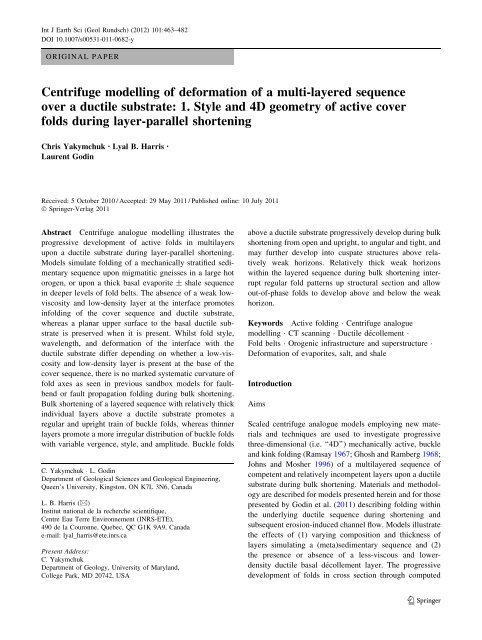
Int J Earth Sci (Geol Rundsch) (2012) 101:463–482DOI 10.1007/s00531-011-0682-yORIGINAL PAPER<strong>Centrifuge</strong> <strong>modelling</strong> <strong>of</strong> <strong>deformation</strong> <strong>of</strong> a <strong>multi</strong>-<strong>layered</strong> <strong>sequence</strong>over a ductile substrate: 1. Style and 4D geometry <strong>of</strong> active coverfolds during layer-parallel shorteningChris Yakymchuk • Lyal B. Harris •Laurent GodinReceived: 5 October 2010 / Accepted: 29 May 2011 / Published online: 10 July 2011Ó Springer-Verlag 2011Abstract <strong>Centrifuge</strong> analogue <strong>modelling</strong> illustrates theprogressive development <strong>of</strong> active folds in <strong>multi</strong>layersupon a ductile substrate during layer-parallel shortening.Models simulate folding <strong>of</strong> a mechanically stratified sedimentary<strong>sequence</strong> upon migmatitic gneisses in a large hotorogen, or upon a thick basal evaporite ± shale <strong>sequence</strong>in deeper levels <strong>of</strong> fold belts. The absence <strong>of</strong> a weak lowviscosityand low-density layer at the interface promotesinfolding <strong>of</strong> the cover <strong>sequence</strong> and ductile substrate,whereas a planar upper surface to the basal ductile substrateis preserved when it is present. Whilst fold style,wavelength, and <strong>deformation</strong> <strong>of</strong> the interface with theductile substrate differ depending on whether a low-viscosityand low-density layer is present at the base <strong>of</strong> thecover <strong>sequence</strong>, there is no marked systematic curvature <strong>of</strong>fold axes as seen in previous sandbox models for faultbendor fault propagation folding during bulk shortening.Bulk shortening <strong>of</strong> a <strong>layered</strong> <strong>sequence</strong> with relatively thickindividual layers above a ductile substrate promotes aregular and upright train <strong>of</strong> buckle folds, whereas thinnerlayers promote a more irregular distribution <strong>of</strong> buckle foldswith variable vergence, style, and amplitude. Buckle foldsC. Yakymchuk L. GodinDepartment <strong>of</strong> Geological Sciences and Geological Engineering,Queen’s University, Kingston, ON K7L 3N6, CanadaL. B. Harris (&)Institut national de la recherche scientifique,Centre Eau Terre Environnement (INRS-ETE),490 de la Couronne, Quebec, QC G1K 9A9, Canadae-mail: lyal_harris@ete.inrs.caPresent Address:C. YakymchukDepartment <strong>of</strong> Geology, University <strong>of</strong> Maryland,College Park, MD 20742, USAabove a ductile substrate progressively develop during bulkshortening from open and upright, to angular and tight, andmay further develop into cuspate structures above relativelyweak horizons. Relatively thick weak horizonswithin the <strong>layered</strong> <strong>sequence</strong> during bulk shortening interruptregular fold patterns up structural section and allowout-<strong>of</strong>-phase folds to develop above and below the weakhorizon.Keywords Active folding <strong>Centrifuge</strong> analogue<strong>modelling</strong> CT scanning Ductile décollement Fold belts Orogenic infrastructure and superstructure Deformation <strong>of</strong> evaporites, salt, and shaleIntroductionAimsScaled centrifuge analogue models employing new materialsand techniques are used to investigate progressivethree-dimensional (i.e. ‘‘4D’’) mechanically active, buckleand kink folding (Ramsay 1967; Ghosh and Ramberg 1968;Johns and Mosher 1996) <strong>of</strong> a <strong>multi</strong><strong>layered</strong> <strong>sequence</strong> <strong>of</strong>competent and relatively incompetent layers upon a ductilesubstrate during bulk shortening. Materials and methodologyare described for models presented herein and for thosepresented by Godin et al. (2011) describing folding withinthe underlying ductile <strong>sequence</strong> during shortening andsubsequent erosion-induced channel flow. Models illustratethe effects <strong>of</strong> (1) varying composition and thickness <strong>of</strong>layers simulating a (meta)sedimentary <strong>sequence</strong> and (2)the presence or absence <strong>of</strong> a less-viscous and lowerdensityductile basal décollement layer. The progressivedevelopment <strong>of</strong> folds in cross section through computed123
464 Int J Earth Sci (Geol Rundsch) (2012) 101:463–482tomodensitometry (CT scanning) and changes in fold orientationand geometry in 3D are presented. Models simulateand help resolve problems in our understanding <strong>of</strong>folds in (1) (meta)sedimentary <strong>sequence</strong>s that constitute asuperstructure upon ductile migmatitic gneisses and (2)within <strong>layered</strong> sedimentary <strong>sequence</strong>s upon a ductile substratesuch as shales ± evaporites in deeper levels <strong>of</strong> foldand thrust belts.Orogenic infrastructure and superstructurein large hot orogensThe concept <strong>of</strong> superstructure and infrastructure (Wegmann1935; Fyson 1971; Murphy 1987; Culshaw et al. 2006) isuseful in distinguishing components <strong>of</strong> an orogenic belt,especially large hot orogens (Beaumont et al. 2006) that,whilst deformed together, display contrasting rheologiesand structural styles and orientation. The superstructuregenerally comprises a weakly metamorphosed to unmetamorphosed<strong>sequence</strong> that acts as an orogenic lid to theunderlying ductile infrastructure. The superstructure mayundergo brittle, brittle-ductile, and ductile <strong>deformation</strong>depending on constituent rock types and is dominated byactive, upright to inclined open to close buckle and/orrounded to angular kink-style folds. The infrastructurecommonly comprises ductile partially molten middle crustthat is <strong>of</strong> a similar density but <strong>of</strong> lesser viscosity than theoverlying superstructure (Rushmer 2001; Mecklenburghand Rutter 2003). The infrastructure is typically dominatedby a shallowly dipping to horizontal foliation and recumbentfolds with variable axes indicative <strong>of</strong> penetrativeductile flow (Roger et al. 2004; Harrowfield and Wilson2005; Williams and Jiang 2005). Separation <strong>of</strong> the superstructurefrom the infrastructure by an essentially planarcrustal-scale décollement is described in the Himalayas(Hodges 2000; Godin 2003; Searle et al. 2003), the westernSuperior Province <strong>of</strong> Canada (Culshaw et al. 2006), theNorth American Cordillera (Murphy 1987; Vanderhaeghe1999; Brown and Gibson 2006), and the inner Piedmont <strong>of</strong>the Appalachians (Hatcher and Merschat 2006). In somecases, however, the superstructure may be infolded into theinfrastructure (e.g. Harris et al. 1987; Chen 1998; Aspleret al. 2002).Modelling presented in this paper illustrates a mechanicallyanalogous process to folding <strong>of</strong> a sedimentarysuperstructural <strong>sequence</strong> following its tectonic juxtapositionupon a ductile infrastructure <strong>of</strong> migmatitic gneissesand granitoids during an initial period <strong>of</strong> layer-parallelshortening. Results have implications for understanding thegeometry and progressive development <strong>of</strong> structures inorogenic systems with a thermally weakened mid-crust,especially how the geometry and style <strong>of</strong> active folds in thesuperstructure vary depending on the presence or absence<strong>of</strong> a low-viscosity and density layer upon the ductile substrateand the factors that promote preservation <strong>of</strong> a flatbasal ductile décollement instead <strong>of</strong> folding <strong>of</strong> the superstructurewithin the infrastructure. Our <strong>modelling</strong> approachwas initially applied to the Himalayan infrastructure–superstructure association in Godin et al. (2011).Active folding <strong>of</strong> layers above a ductile décollementin fold and thrust beltsModels also simulate an analogous situation in many foldbelts where a sedimentary <strong>sequence</strong> <strong>of</strong> mechanicallyactive, competent layers (such as quartzite or limestone)interbedded with thin incompetent shale horizons overlie athicker shale or evaporitic ± shale <strong>sequence</strong> that constitutesa ductile substrate. Whereas sandbox experimentsprovide valuable information <strong>of</strong> structures in the uppercrust where layers deform as Coulomb wedges (Davis et al.1983), for fault-bend folding (Suppe 1983; Suppe et al.2004) and fault-propagation folding (Mitra 1990), ourmodels simulate deeper levels <strong>of</strong> fold belts and/or whereactive buckle folding has taken place due to mechanicaldifferences between layers that deform in a ductile manner.In select models, a low-density and low-viscosity layer isincorporated at the base <strong>of</strong> half <strong>of</strong> the cover <strong>sequence</strong> thatis analogous to a horizon <strong>of</strong> salt and/or pure gypsum. Thepresence or absence <strong>of</strong> this layer is used to test its effectson the regional curvature <strong>of</strong> fold axes and the development<strong>of</strong> décollement or detachment controlled salients as proposedby Macedo and Marshak (1999), Affolter and Gratier(2004), and Sussman et al. (2004).Why centrifuge <strong>modelling</strong>?Apart from 3D models <strong>of</strong> fold development (e.g. Kaus andSchmalholz 2006), most numerical models, especially <strong>of</strong>regional tectonic processes such as channel flow (e.g.Beaumont et al. 2001, 2004, 2006; Jamieson et al. 2004;Culshaw et al. 2006) and <strong>deformation</strong> <strong>of</strong> thin-skinned foldand-thrustbelts (e.g. Stockmal 2007; Simpson 2009),provide only 2D, cross-sectional views. Despite thedevelopment <strong>of</strong> 3D <strong>modelling</strong> codes such as Ellipsis 3D(O’Neill et al. 2006) and Underworld (Humble 2008) thatcan simulate ductile flow, folding, and shearing at highstrains, numerical models generally lack the resolution toimage discrete structures in fine detail and, whilst providinga valuable overview, commonly do not portray subtle,detailed features akin to those that may be observed in thefield or from high-resolution seismic data. Numericalmodels examining the interplay between folding andfaulting <strong>of</strong> a competent <strong>sequence</strong> over a weak décollementin upper-crustal layers have demonstrated the conditionsnecessary for buckle folding to dominate but have not123
Int J Earth Sci (Geol Rundsch) (2012) 101:463–482 465addressed the significance <strong>of</strong> infolding (Simpson 2009) andfactors controlling whether detachment or infolding willoccur. Despite advances in numerical <strong>modelling</strong> andinherent limitations <strong>of</strong> analogue models (described below),scaled analogue models therefore still provide a bettermeans to study the coeval progressive evolution <strong>of</strong> structuresat upper- and mid-crustal levels in fine detail andin 3D.There has been extensive 1g 1 physical <strong>modelling</strong> <strong>of</strong>fault-related folding <strong>of</strong> upper-crustal sedimentary strataabove a ductile substrate or ductile detachment zone representinga salt or shale horizon in nature (e.g. Turrini et al.2001; Bahroudi and Koyi 2003; Luján et al. 2003, 2006;Sokoutis et al. 2005) and during channel flow (Mukherjeeand Koyi 2009). Some sandbox experiments (e.g. Lujánet al. 2003, 2006; Nilforoushan and Koyi 2007; Vidal-Royoet al. 2009) illustrate the effects <strong>of</strong> localized ductiledécollements. Fewer experiments, however, investigateactive buckle folding and whilst highly valuable, generallydate to before advances in model visualization throughmodern computing. For example, Bucher (1956) usedstitching wax (a resin with a plasticiser that deforms as anviscoelastic material) layers in petrolatum grease and Blayet al. (1977) used gelatine <strong>multi</strong>layers on a thin, lubricatedbase layer deformed by gravity gliding and (in separateexperiments) by lateral compression at 1g to simulate folddevelopment and geometry above a ductile substrate.<strong>Centrifuge</strong> <strong>modelling</strong> is, however, considered as a bettermeans to simulate active, buckle folding <strong>of</strong> a <strong>multi</strong>-<strong>layered</strong><strong>sequence</strong> over a ductile substrate as it:1. Enables viscous and plastic materials to be used toreplicate ductile <strong>deformation</strong> incorporating activemechanical anisotropies at different levels in the crust(Ramberg 1973, 1981; Dixon and Summers 1985; Hillet al. 2010);2. Achieves dynamic scaling <strong>of</strong> models to account forbody forces (Hubbert 1937; Ramberg 1967a, b, 1973,1981; Weijermars and Schmeling 1986; developed inthe ‘Scaling’ section below), which are especiallyimportant when a low-density and viscosity layer isincluded in models;3. Allows the use <strong>of</strong> more viscous <strong>modelling</strong> materialsthat are easier to manipulate to scale <strong>deformation</strong> <strong>of</strong>the upper crust and middle crust than those that areused in normal gravity experiments (Ramberg 1967a,b, 1981; Weijermars and Schmeling 1986).A detailed explanation <strong>of</strong> the centrifuge method isprovided by Ramberg (1981) and Dixon and Summers(1985).1 Where g is the local acceleration due to gravity, i.e., 1g experimentsare carried out under normal gravity.Model preparation and scalingMaterialsModels are constructed to replicate a natural prototypeconsisting <strong>of</strong> a simplified two-<strong>layered</strong> crustal pr<strong>of</strong>ile <strong>of</strong> anupper-<strong>layered</strong> undeformed flat-lying sedimentary rock<strong>sequence</strong> resting upon a ductile substrate (Fig. 1). Modellingmaterials (Table 1) have densities and viscositiesscaled to simulate the upper crust and mid crust to lowercrust when accelerated at ca. 1,000g and are similar tothose used in previous centrifuge <strong>modelling</strong> studies (Dixonand Summers 1983, 1985; Jackson et al. 1988; Dixon andTirrul 1991; Koyi and Skelton 2001; Koyi and Harris 2001;Harris and Koyi 2003; Dixon 2004; Corti 2004; Hill et al.2010; Godin et al. 2011). Low-density Crayola Ò <strong>modelling</strong>clay is used to decrease the density <strong>of</strong> the upper-crustal<strong>layered</strong> <strong>sequence</strong> with a minimal effect on the effectiveviscosity to achieve scaled densities to the prototype.Introduction <strong>of</strong> this low-density material avoids the use <strong>of</strong>barium sulphate and acids, commonly used to increase thedensity <strong>of</strong> silicone putties but which can significantlychange the rheology <strong>of</strong> the materials (ten Grotenhuis et al.2002). Viscosity curves for materials used to construct theductile substrate are shown in Fig. 2. Columns depictingthe composition and geometry <strong>of</strong> individual models areshown in Fig. 3.Microlaminates composed <strong>of</strong> Demco Ò <strong>modelling</strong> clay,hereafter referred to as ‘DMC’, Dow Corning DilatantCompound 3179 (DC 3179) alone or mixed with the lowdensityCrayola Ò Model Magic (CMM) simulate a succession<strong>of</strong> competent, but ductile clastic and carbonaterocks interbedded with incompetent pelitic and semi-peliticrocks. The DMC used in this study is rheologically similarto plasticine (McClay 1976; S<strong>of</strong>uoglu and Rasty 2000;Zulauf and Zulauf 2004) that is used to construct microlaminatesin other centrifuge studies (e.g. Dixon andSummers 1985; Dixon and Tirrul 1991; Hill et al. 2010).Microlaminates are prepared using the rolling and stackingmethod employed by Dixon and Summers (1985), but anelectric dough break was used for rolling. To decrease thedensity <strong>of</strong> the microlaminates as required for scaling, thethickest layers <strong>of</strong> DMC are thoroughly mixed with CMM ata 40:60 weight ratio (DMC-60). A thin layer (1–2 mm) <strong>of</strong> alow-density CMM is placed at the surface (Fig. 1) toeliminate an otherwise too great a contrast between the top<strong>of</strong> the <strong>layered</strong> <strong>sequence</strong> and air, which may affect thegeometry <strong>of</strong> folds in upper microlaminates. This study doesnot include upper-crustal brittle structures due to difficultiesin incorporating cohesive layers that undergo faultingin the centrifuge (where layers are placed vertically precludinguse <strong>of</strong> unconsolidated, e.g. granular materials) andhave the required density. No attempt is made to introduce123
466 Int J Earth Sci (Geol Rundsch) (2012) 101:463–482Fig. 1 Analogue modelconstruction and initialdimensions. A collapsing wedgecomposed <strong>of</strong> Dow Corning 3179Dilatant Compound that appliesa force on a weighted nylonplate is used to shorten themodel in the centrifuge. Anadditional low-viscosity anddensity polydimethylsiloxane(PDMS) layer at the interface <strong>of</strong>the <strong>layered</strong> cover <strong>sequence</strong> andductile substrate is present inmodels 54, 59, and 6180 mmCollapsing wedgeNylon plateWeightCrayola Model MagicLayered <strong>sequence</strong>200 mm15 mmDuctile substrate± Low viscositylow density layerTable 1 Rheological properties <strong>of</strong> <strong>modelling</strong> materialsModel material Prototype Effective viscosity(Pa s) aCover microlaminatesSedimentary cover <strong>sequence</strong> (large hot orogensand deeper levels <strong>of</strong> fold-thrust belts)Bulk density(kg m -3 )(\1.05)Dow Corning 3179 bDilatant Compound (DC 3179)Weak ductile cruste.g. shales4 9 10 5 1.133Crayola Model Magic (CMM) Uppermost layer – 0.504Plasticine cCompetent ductile crust8 9 10 6 –6 9 10 9 1.7e.g. quartzites or carbonatesDemco Modelling Clay (DMC)Competent ductile cruste.g. impure quartzites or marlsSimilar to plasticine 1.167Demco Modelling Clay (60%)/Crayola Model Magic(40%) (DMC-60)Weak ductile cruste.g. impure quartzites or marls– 0.900Ductile substrate Large hot orogens Fold-thrust belts (*1.05)PDMS Leucogranites Salt or gypsum 2–3 9 10 4b,d 0.979Crazy Aaron’s thinking putty (CATP) Melt-weakened lower crust Evaporites ± shales 1.5 9 10 4–5 1.05a At <strong>modelling</strong> strain ratesb Konstantinovskaya et al. (2007)c McClay (1976)d Boutelier et al. (2008)fault-susceptible layers within the microlaminates as thisstudy is concerned only with active buckle folding withoutfaults. Each individual model has slight variations in layerthickness due to imperfections in construction (Fig. 3),except for doubly-thin layers in model 61, but the rheologicaleffects are interpreted to be minor compared to themechanical contrast between the <strong>layered</strong> <strong>sequence</strong> andductile substrate. The average density <strong>of</strong> the <strong>layered</strong><strong>sequence</strong> ranges from 0.96 to 1.10 g cm -3 . The effectiveviscosities <strong>of</strong> the <strong>layered</strong> <strong>sequence</strong>s range from 10 5 to10 6 Pa s at experimental strain rates (ca. 5.0 9 10 -4 s -1 ),based on the viscosity <strong>of</strong> <strong>layered</strong> <strong>sequence</strong>s with a similarcomposition from other studies (Koyi and Skelton 2001;Harris et al. 2002; Harris and Koyi 2003).The ductile substrate is prepared by stacking layers <strong>of</strong>Crazy Aaron Enterprise’s Thinking Putty Ò (CATP), a123
Int J Earth Sci (Geol Rundsch) (2012) 101:463–482 467Log viscosity [Pa s]654-4DC 3179DC 3179 + Glow (4%)CATP silverCATP amberCATP amber + Glow (4%)PDMS-3 -2 -1 0 1Log strain rate [s-1]Layered <strong>sequence</strong>Model60 6154 5259****5 mm = 5 kmFig. 2 Compilation <strong>of</strong> flow properties <strong>of</strong> Dow Corning 3179 dilatantcompound (DC 3179) (Poulin 2006), Crazy Aaron Thinking Putty(CATP; Poulin 2006), and polydimethylsiloxane (PDMS; Weijermars1986; Sokoutis 1987; ten Grotenhuis et al. 2002). Flow properties arealso shown for DC 3179 and CATP with an added 4% weight <strong>of</strong>strontium aluminate-europium powder used to produce marker layerson computed tomodensitometry scans (Poulin 2006; Konstantinovskayaet al. 2007)Ductile substrate**silicone putty with scaled densities and viscosities similarto Rhodorsil Gomme Silbion described by Weijermars(1986) and Hailemariam and Mulugeta (1998) that representductile mid-crust (Table 1). Different colours andradiometric properties (see section below on CT scanning)are used for visual contrast, but these different layersexhibit only minor rheological variations (Poulin 2006).Densities <strong>of</strong> the putties range between 1.05 and1.08 g cm -3 , which is slightly denser to within error <strong>of</strong> thedensity for the overlying <strong>layered</strong> <strong>sequence</strong>. The viscosity <strong>of</strong>the putties ranges from 10 4 to 10 6 Pa s at the estimatedexperimental strain rates (c. 5.0 9 10 -4 s -1 ; Fig. 2), aboutan order <strong>of</strong> magnitude less than the <strong>layered</strong> <strong>sequence</strong>,which is considered a reasonable approximation <strong>of</strong> viscositycontrasts that exists in nature between the uppercrust and a melt-weakened mid-crust (Rosenberg andHandy 2005). In models 54 and 61, a 2 mm layer <strong>of</strong>polydimethylsiloxane (PDMS; Weijermars 1986; Boutelieret al. 2008) is placed between the <strong>layered</strong> <strong>sequence</strong> andductile substrate lengthwise across half <strong>of</strong> the model parallelto the shortening direction to investigate mechanicaldecoupling, whereby both layers <strong>of</strong> the model deformindependently to each other, across this interface (Figs. 1,3). PDMS has been previously used to simulate granitoidintrusions (e.g. Dietl and Koyi 2008) or salt (e.g. Koyi1991; Forien and Dietl 2009) in centrifuge models incorporatingother silicone putties ± <strong>modelling</strong> clays.Materials used to emulate the mid-crust exhibit a non-Newtonian behaviour defined by the flow law:r n ¼ leLayered <strong>sequence</strong>DMCDC 3179DMC-60CMMPlasticineRigid BaseDuctile substrateDMCCATPPDMS* 4% by weightstrontium europiumaluminatepowderFig. 3 Construction <strong>of</strong> an upper-<strong>layered</strong> <strong>sequence</strong> overlying a ductilesubstrate. The <strong>layered</strong> <strong>sequence</strong> is composed <strong>of</strong> a repetitive <strong>sequence</strong><strong>of</strong> microlaminates (c.f. Dixon and Summers 1985). The ductilesubstrate consists <strong>of</strong> inter<strong>layered</strong> silicone putties <strong>of</strong> different coloursthat exhibit minimal dynamic variation. Individual models showslight variations in layer thickness. An asterisk adjacent to a layerindicates that it contains 4% weight strontium europium-aluminatepowder (Ultra Green Glow in the Dark Powder TM from Glow Inc.).CATP: Crazy Aaron Thinking Putty, CMM: Crayola Ò Model Magic,DC 3179: Dow Corning Dilatant Compound 3179, DMC: Demco Ò<strong>modelling</strong> clay, DMC-60: Demco Ò <strong>modelling</strong> clay mixed with 40%Crayola Ò Model Magic, PDMS: polydimethylsiloxaneð1Þwhere l = viscosity, e = strain rate, r = stress, and n isthe power law exponent. Materials with n = 1 exhibit alinear relationship between stress and strain, or Newtonianbehaviour. Materials with n [ 1 have a variable viscositydepending on the strain rate. The effective dynamic viscosity<strong>of</strong> materials that model the ductile mid-crust isdefined here as l eff = r/e and plotted against increasingstrain rates in Fig. 2. At this strain rate, the effective viscosity<strong>of</strong> the <strong>layered</strong> <strong>sequence</strong>, ductile substrate, and123
468 Int J Earth Sci (Geol Rundsch) (2012) 101:463–482PDMS are c. 1 9 10 6–8 , 2 9 10 5 , and 4 9 10 4 Pa s,respectively.ScalingModels are scaled to simulate a simplified orogenic system.Scaling <strong>of</strong> dynamic, geometric, and rheological propertiesis achieved by scaling the gravitational stress r using theequation:r ¼ q g l ð2Þwhere q, g, and l are density, gravity, and length, respectively,and the asterisk denotes the dimensionless ratiobetween the model and the prototype (Hubbert 1937;Ramberg 1967a, b, 1973, 1981; Dixon and Summers 1985).Models are scaled to the prototype with a length scalingratio <strong>of</strong> l = 1 9 10 6 , whereby 1 mm in the model represents1 km in the prototype (the same as in many othercentrifuge experiments <strong>of</strong> fold-thrust belts, such as Dixonand Spratt 2004; Hill et al. 2010). The scaling ratios fordensities, stress, time, acceleration, velocity, and viscosityare shown in Table 2.Model limitationsThe geometries and rheological properties <strong>of</strong> the <strong>layered</strong><strong>sequence</strong> and the ductile substrate are necessary simplifications<strong>of</strong> a natural complex and heterogeneous system.These models cannot account for inherited structures andstrength anisotropies, which may locally affect stress fieldsand influence the geometry <strong>of</strong> folds. The rheology <strong>of</strong> rocksis temperature, confining pressure, strain-rate, and pore andfluid pressure dependent, which is simplified here into atwo-<strong>layered</strong> model representing the upper- and mid-crustseparated by an abrupt interface. As the rheology <strong>of</strong> rocksin nature is not well constrained, materials are used thatdisplay a significant enough viscosity contrast to be a goodapproximation. Models initially contain a ductile substrate;however, in a typical orogenic setting, the lower substratewould start strong and progressively weaken aftercrustal thickening and a period <strong>of</strong> thermal incubation (e.g.Beaumont et al. 2004). Model construction, especially inrolling more competent layers, introduced some minorheterogeneities in some layers and some small bubblesremained in silicone layers despite care in their preparation.However, such small initial heterogeneities areimportant in nucleating some structures in the ductilesubstrate, although a discussion <strong>of</strong> this is beyond the scope<strong>of</strong> the present paper.Model preparation and <strong>deformation</strong>The PR-7000 centrifuge at INRS-ETE in Quebec City(modified for physical <strong>modelling</strong> by the Bureau <strong>of</strong> EconomicGeology, University <strong>of</strong> Texas at Austin) is capable <strong>of</strong>subjecting models up to 200 mm 9 80 mm in plan view toaccelerations exceeding 8,000g. Materials are rolled to adesired thickness, encased on all sides with plastic plates,and frozen to facilitate handling. The frozen <strong>layered</strong><strong>sequence</strong> is placed upon the frozen ductile substrate,encased on all sides and allowed to return to room temperaturebefore being placed in the centrifuge. Due to thetendency <strong>of</strong> the silicone putties to flow under normal gravityat room temperature, all sides <strong>of</strong> the model are covered in athin layer (\1 mm thick) <strong>of</strong> DMC to prevent the puttiesfrom escaping the model chamber. In preparing all models,every side <strong>of</strong> the completed model is coated in a thin layer<strong>of</strong> silicon plumbers grease and covered with a slice <strong>of</strong>overhead transparency plastic film to minimize boundaryeffects during shortening. The prepared model is orientedvertically in the centrifuge chamber, and a counterweight isplaced in a chamber on the opposite side <strong>of</strong> the centrifuge tomaintain balance. Each model is run for 6–8 stages, eachat c. 1,000g for 360 s with a run-up time <strong>of</strong> 60 s and aTable 2 Scaling properties <strong>of</strong> models and prototypesQuantity Model Prototype Scaling ratioLength ratio 1 mm 1 km l r = l m /l p = 1 9 10 -6Density (bulk) (kg m -3 )Layered <strong>sequence</strong> 1,050 2,700 q r = q m /q p = 0.39Ductile substrate 1,050 2,700 q r = q m /q p = 0.39Acceleration 1,000 1 a r = 1,000Velocity (mm year -1 ) 2.2 9 10 6a 58 v r = l r /t r = 3.8 9 10 4Time 360 s 0.44 My t r = l r /l r q r a r = 2.6 9 10 -11Viscosity (Pa s) b 1 9 10 5 1 9 10 19 l r = l m /l p = 1 9 10 -14Subscripts ‘m’ and ‘p’ denote model and prototype, respectivelya Calculated for 25 mm shortening each runb At experimental strain rates <strong>of</strong> c. 5 9 10 -4 s -1123
Int J Earth Sci (Geol Rundsch) (2012) 101:463–482 469run-down time <strong>of</strong> 420 s. In between each stage, the model ispartially frozen and a vertical section is cut parallel to theshortening direction to be photographed *5 mm from eachend <strong>of</strong> the model. Models are then reassembled and allowedto return to room temperature before going through anotherstage. New slices are made at 5 mm increments towards thecentre <strong>of</strong> the model after each stage.Initial model dimensions are 170–200 mm 9 80 mm inplan view by 15–20 mm in height (Fig. 1). Models consist<strong>of</strong> a <strong>layered</strong> <strong>sequence</strong> 8–10 mm thick overlying a ductilesubstrate 5–6 mm thick. Initial layer thickness and modelgeometries for individual models are given in Table 3 andFig. 3. The model is progressively shortened in 2–4 stagesvia a collapsing wedge <strong>of</strong> DC 3179 30 mm 9 80 mm inplan view by 50 mm in height (c.f. Dixon and Summers1985; Jackson et al. 1988; Dixon and Tirrul 1991; Johnsand Mosher 1996). The wedge is confined on four facesand is free to collapse parallel to the long axis <strong>of</strong> the model.The wedge induces layer-parallel shortening by collapsingbehind the model to equilibrate radial pressure gradientswithin the wedge, consequently forcing the nylon platetowards the model (Fig. 1). A plastic plate with a weightedbase is inserted between the model and the collapsingwedge (as in Johns and Mosher 1996) to provide an equaldistribution <strong>of</strong> force throughout the back face <strong>of</strong> the model.Computed tomodensitometry (‘‘CT scanning’’)Computed tomodensitometry, also known as computedtomography or commonly as CT scanning, is used to obtain3D information <strong>of</strong> the progressive evolution <strong>of</strong> severalmodels. For a detailed explanation <strong>of</strong> the techniques <strong>of</strong>X-ray computed tomography and geological and analogue<strong>modelling</strong> applications, readers are referred to Duliu(1999), Ketcham and Carlson (2001), Mees et al. (2003),and Poulin (2006). CT scanning is a passive method toimage models in 3D and extract model cross sections andplan views, at various heights in the model analogous toviewing different depths or erosion levels. In addition, CTscans allow 3-dimensional reconstruction <strong>of</strong> models. CTscanning has been successfully used in sandbox studies toimage individual layers (e.g. Colletta et al. 1991; Konstantinovskayaet al. 2007), but due to problems in attenuation<strong>of</strong> X-ray energy and in resolving thin layers <strong>of</strong>similar density, CT scanning has rarely been used formodels incorporating <strong>modelling</strong> clays and silicone putties.For cohesive materials in analogue models, apart for thedevelopment <strong>of</strong> CT-scanning techniques in <strong>multi</strong>layermaterials (Poulin 2006) used in our research and experimentson diapir emplacement (Harris et al. 2008), CTscanninghas been only previously used to image a singlediscrete boudinaged plasticine layers (e.g. Zulauf et al.2003; Zulauf and Zulauf 2005) or basal silicone layers in asandbox (e.g. Konstantinovskaya et al. 2007).Two centrifuge models were constructed and scannedbetween each <strong>deformation</strong> stage using a Siemens SomatonSensation medical CT-Scanner. To improve image contrast,approximately 4 wt% <strong>of</strong> strontium aluminate-europiumpowder (Ultra Green Glow in the Dark Powder TM fromGlow Inc. Ò composed <strong>of</strong> a proprietary combination <strong>of</strong>Al 2 O 3 –SrCO 3 –Eu 203 –Dy 203 –TiO 2 ) is added to specificlayers (denoted by an asterisk in Fig. 3). In some models,the ductile substrate contains a single layer <strong>of</strong> amber CATPthat is easily imaged without the addition <strong>of</strong> the powder.This method developed by Poulin (2006) was successfullyemployed in sandbox (Konstantinovskaya et al. 2007) andcentrifuge experiments (Harris et al. 2008). The Glow in theDark powder induces a Compton scattering effect thatTable 3 Initial setup and geometry <strong>of</strong> modelsLayered <strong>sequence</strong>Model 60 Model 61 Model 54 Model 52 Model 59Thickness (mm) 810101010Layer repetition 16× 32× 16× 16× 16×Interface– Half PDMS(2 mm)Half PDMS(2 mm)Ductile <strong>sequence</strong>Thickness (mm) 55665Composition – – – Competent layer –Initial length (mm)Shortening stagesTotal shortening (%)180232190237170342–200225Full PDMS(1 mm)170342123
470 Int J Earth Sci (Geol Rundsch) (2012) 101:463–482decreases the energy <strong>of</strong> reflected X-rays that mimics greaterdensity contrasts in the CT scanner but only increases thetrue density <strong>of</strong> the materials by\5% whilst the viscosity <strong>of</strong>materials is minimally affected by the addition <strong>of</strong> thepowder (Fig. 2; Poulin 2006). The scanner is set up for aradial scanning pattern with an isotropic resolution <strong>of</strong>0.24 mm. Image analysis and processing is conducted usingOsiriX medical imaging s<strong>of</strong>tware (Rosset et al. 2004). 3Dvolumes were constructed by interpolating betweenapproximately 430 individual slices using 3D volume renderingprotocols formulated in Osirix. Optimal parameterswere developed to visualize several marker layers in models;the slight radiometric density contrasts between somelayers, especially in the ductile substrate, make it extremelydifficult to clearly image some <strong>of</strong> the thin layers.Differences to previous centrifuge studiesApart from centrifuge models by Dennis and Häll (1978),Koyi (1988), and Sans and Koyi (2001) active buckledetachment-related folding above a (relatively) thick ductilesubstrate without contemporaneous faulting in eitherthe basal or cover <strong>sequence</strong> has received little attention.Most previous centrifuge models <strong>of</strong> the progressivedevelopment and 3D geometry <strong>of</strong> structures in fold andthrust belts have used simple plasticine and silicone puttymicrolaminates directly overlying a rigid base (e.g. Dixonand Tirrul 1991; Dixon 2004), basal layers <strong>of</strong> competent<strong>modelling</strong> clay (e.g. Dixon and Spratt 2004; Hill et al.2010), or cardboard and wax (Hynes and Dixon 2005) andstudied the interaction between folding and faulting. InDixon’s (2004) centrifuge models, localized detachmenthorizons were simulated by simply lubricating a layer withpetroleum jelly. <strong>Centrifuge</strong> models that include the investigation<strong>of</strong> differences in layer thickness on fold geometryover a thin ductile layer during shortening are presented inAydemir (1998); however, these models are extremelysimple and the ductile basal layer is relatively thin; thesemodels are more applicable to upper crustal <strong>deformation</strong> atthe local scale (which was their intended purpose).Our centrifuge <strong>modelling</strong> goes beyond experiments atnormal laboratory conditions by Bucher (1956) and centrifugemodels <strong>of</strong> Dennis and Häll (1978), Koyi (1988) andSans and Koyi (2001) in studying the effects <strong>of</strong> a ductilesubstrate and the role <strong>of</strong> a low-viscosity and densitydetachment horizon for part <strong>of</strong> some models in 4D. Ourmodels differ significantly from Koyi (1988) and Sans andKoyi (2001) in that they do not address the process <strong>of</strong>diapirism and diapir-fold interaction as, apart from thePDMS layer used in part <strong>of</strong> some models described below,the thick ductile substrate and cover <strong>sequence</strong> are <strong>of</strong> similardensity, achieved by using lower-density <strong>modelling</strong> claymixes than in previous research. Tomodensitometry (‘‘CTscanning’’) techniques used in some <strong>of</strong> our models providefor the first time an exceptional view <strong>of</strong> the progressivedevelopment <strong>of</strong> structures in 3D.ResultsFolding <strong>of</strong> a <strong>layered</strong> <strong>sequence</strong> directly upon a ductilesubstrate (Model 60)The model consists <strong>of</strong> a finely <strong>layered</strong> <strong>sequence</strong> upon aductile and mechanically homogenous substrate. In contrastto models 61 and 54 (described below), no low-viscosity/low-densitylayer is present along the interfacebetween cover <strong>sequence</strong> and substrate. During progressiveshortening, folds in the <strong>layered</strong> cover <strong>sequence</strong> propagatefrom the advancing end wall <strong>of</strong> the model towards the fixedend (Fig. 4a–c). Folds are developed across the length <strong>of</strong>the model. Fold style and wavelength are variable. Abroad, rounded antiform develops in front <strong>of</strong> the advancingram (Fig. 4b, c). As folds tighten, initial box folds evolveinto more angular folds (Fig. 4b, c) through hinge migrationand axial surface rotation. Synformal axial planes areFig. 4 Model 60. Photographs <strong>of</strong> vertical sections at a distance <strong>of</strong> *5 mm from each other towards the centre <strong>of</strong> the model after each stage inthe centrifuge. See text for discussion. a Layers before shortening and addition <strong>of</strong> uppermost white layer, b 22% shortening, c 33% shortening123
Int J Earth Sci (Geol Rundsch) (2012) 101:463–482 471nearly vertical at the top <strong>of</strong> the model and graduallybecome reclined towards the ductile substrate (Fig. 4c).The folds have a dominant wavelength <strong>of</strong> 7 mm in the<strong>layered</strong> cover <strong>sequence</strong> and 3 mm in the ductile substrate(i.e. equivalent to 7 and 3 km in nature, respectively). Theinterface separating the <strong>layered</strong> <strong>sequence</strong> and the ductilesubstrate is folded with sharp cuspate antiforms and broadopen synforms.Folding <strong>of</strong> a <strong>layered</strong> <strong>sequence</strong> over a two-<strong>layered</strong>ductile substrate (Models 61 and 54)Two models (Models 61 and 54) investigated the contrasting<strong>deformation</strong> styles between a <strong>layered</strong> <strong>sequence</strong> and theductile substrate with and without an intermittent weakdécollement zone (Figs. 1, 3). The <strong>layered</strong> <strong>sequence</strong> containsfiner layers than other models to also investigate the influence<strong>of</strong> layer thickness on buckle folds in the <strong>layered</strong> <strong>sequence</strong>. Alow-viscosity polymer, PDMS (2 mm thick), is incorporatedfor half the uppermost ductile substrate to investigate theeffect <strong>of</strong> a weak ductile décollement horizon. For example,the PDMS horizon simulates leucogranites emplaced during<strong>deformation</strong> along the interface separating the upper- andmid-crust, as documented in the Himalaya (Searle et al. 1997,2003) and modelled in Godin et al. (2011), and the Thor Odindome <strong>of</strong> the Canadian Cordillera (Vanderhaeghe 1999), or apure gypsum or salt layer between a sedimentary cover<strong>sequence</strong> and an evaporitic ± shale substrate in a sedimentary<strong>sequence</strong> <strong>of</strong> a fold belt. Sequential photographs <strong>of</strong> bothhalves <strong>of</strong> the model are presented in Fig. 5, showing theevolution <strong>of</strong> the PDMS-present (left side) and PDMS-absenthalves <strong>of</strong> the model (right side).Progressive shortening <strong>of</strong> the <strong>layered</strong> <strong>sequence</strong> <strong>of</strong> Model61 produces tight to open, chevron to sharp folds <strong>of</strong> variablevergence (Fig. 5). Where the PDMS layer is present, foldsverge towards the moving end plate equivalent tohinterland-verging folds in nature, whereas folds where noPDMS layer is present are more upright and where inclined,tend to verge away from the moving end plate, i.e., equivalentto foreland verging in nature. During the shorteningstages (a, b in Fig. 5), a flat decoupling interface developsbetween the PDMS and the denser and more viscous ductilesubstrate, and the PDMS layer flows laterally to infill antiforms.In the PDMS-absent half <strong>of</strong> the model, the interfaceis folded and folds in the ductile substrate mimic those inthe <strong>layered</strong> <strong>sequence</strong>. After final shortening (Stage B inFig. 5), folds in the PDMS-absent half are generally tighter,more angular, than the more open, sub-rounded, and uprightfolds above the PDMS. The largest folds above the PDMShave greater amplitudes (19 mm) than the largest foldsdirectly above the ductile substrate (17 mm; Fig. 5). Foldsabove the PDMS-absent half <strong>of</strong> the model have a smallerdominant wavelength (9 mm) and greater variety <strong>of</strong> foldwavelengths than those above the PDMS (17 mm averagedominant wavelength). Two prominent box folds developabove the PDMS-absent half <strong>of</strong> the model at the forelandsidein stage B (Fig. 5). The PDMS layer thickens beneathantiforms in the <strong>layered</strong> <strong>sequence</strong> and thins beneath synforms(Stage B in Fig. 5). Both interfaces between the<strong>layered</strong> <strong>sequence</strong> and ductile substrate and between theuppermost low-density and lesser viscosity (DMC) <strong>modelling</strong>clay layer display cuspate-lobate structures where thecusps point towards the more competent cover <strong>sequence</strong>similar to mullions formed during layer-parallel shorteningdescribed by Ramsay (1967) and Urai et al. (2001). This isseen on both sides <strong>of</strong> the model but is more prominent onthe PDMS-absent side <strong>of</strong> the model (Fig. 5).The second model that investigates the effect <strong>of</strong> a weakdécollement zone on folding in the cover <strong>sequence</strong>(Model 54) is similar to the previously described model(Model 61). This model was also prepared for CT imaging.Half <strong>of</strong> the ductile substrate is capped with 2 mm <strong>of</strong> PDMSFig. 5 Model 61. Successive photographs 5 mm from each otherfrom both ends <strong>of</strong> the model towards the centre. One half <strong>of</strong> the modelcontains a layer <strong>of</strong> PDMS at the interface (left) and one half withoutPDMS (right). a Undeformed, b, c Stage A: 14% shortening, d,e Stage B: 29% shortening123
472 Int J Earth Sci (Geol Rundsch) (2012) 101:463–482Fig. 6 Photograph <strong>of</strong> Model 54 after 42% shortening. One half <strong>of</strong> themodel contains a layer <strong>of</strong> PDMS at the interface between the <strong>layered</strong><strong>sequence</strong> and ductile substrate, and the other half has no PDMS alongthis interfaceand the other half is covered with yellow CATP (Fig. 3).Oblique model photographs and 3D model reconstructionsfrom CT images are shown in Figs. 6 and 7, respectively.During bulk shortening (stages A to C in Fig. 7), folds in the<strong>layered</strong> <strong>sequence</strong> progressively propagate from theadvancing endplate towards the fixed end (equivalent t<strong>of</strong>oreland propagation). Folds are non-cylindrical and differin style depending on the nature <strong>of</strong> the substrate. Initial foldsabove half <strong>of</strong> the model with a PDMS substrate have smalleramplitudes than folds on the opposite side with no PDMS inStage A (Fig. 7b, c). Initially round folds tighten andbecome sub-angular towards the hinterland end <strong>of</strong> themodel, and new angular folds nucleate in the foreland duringstage B (Fig. 7d, e). Rounded open folds above the PDMSlayer laterally change to sub-angular, tighter folds towardsthe PDMS-absent half <strong>of</strong> the model (Fig. 7, stage B). Duringthe final shortening stage (stage C in Fig. 7), all folds progressivelytighten and are sub-angular to angular. Fold axialtrace across the top <strong>of</strong> the model is slightly arcuate and moreso above the PDMS (Fig. 7f, g). Importantly, however, thereis no simple constant sense <strong>of</strong> curvature <strong>of</strong> fold axes acrossthe PDMS-present and PDMS-absent halves <strong>of</strong> the model,i.e., folds may curve across the interface in both senses.Folds are doubly plunging and conical. A single angular foldabove the PDMS-absent half <strong>of</strong> the model graduallybecomes rounded and bifurcates into two angular foldsabove the PDMS transition zone (Fig. 7f, g). After the finalshortening stage (stage C in Fig. 7), the interface betweenthe PDMS and the ductile substrate remains relatively planarcompared to undulating interface without the PDMS.Folding <strong>of</strong> thicker cover <strong>sequence</strong> layers over a ductilesubstrate with a thin competent layer (Model 52)This model investigates the influence <strong>of</strong> layer thickness onthe development <strong>of</strong> buckle folds in the <strong>layered</strong> <strong>sequence</strong>where individual thicknesses <strong>of</strong> cover <strong>sequence</strong> layers aretwice those <strong>of</strong> Model 61 (previously described) butconstructed <strong>of</strong> the same materials (Fig. 3) and where thereis a single competent layer within the ductile substrate.This model lacks a Crayola Model Magic cover (Fig. 3).Bulk shortening produces a consistent train <strong>of</strong> open andupright folds in the cover <strong>sequence</strong> with an averagewavelength <strong>of</strong> 9 mm (Fig. 8a, b). Folds initiate as open andround folds and progressively tighten into sub-angularfolds at the interface with the ductile substrate and becomebox folds towards top <strong>of</strong> the model (Fig. 8b). Folds in the<strong>layered</strong> <strong>sequence</strong> initiate and remain upright through thebulk shortening stages (Fig. 8a, b). The interface betweenthe <strong>layered</strong> <strong>sequence</strong> and the ductile substrate is folded bynumerous antiformal cuspate structures (Fig. 8b). Folds inthe <strong>layered</strong> cover <strong>sequence</strong> are independent to those <strong>of</strong> thecompetent layer in the middle <strong>of</strong> the ductile substrate andsome are completely out <strong>of</strong> phase (i.e. synform beneathantiform), although wavelengths are similar.Folding <strong>of</strong> two competent layer packages separatedby a ductile layer in the cover <strong>sequence</strong> (Model 59)This model differs from previously described models inthat the cover <strong>sequence</strong> is composed <strong>of</strong> two laminatedpackages dominated by <strong>modelling</strong> clay with thin interbeddedsilicone layers separated by a 2-mm thick siliconelayer (with a thin internal <strong>modelling</strong> clay marker). Thislayer acts as an internal ductile décollement horizon withinthe cover <strong>sequence</strong> as seen in the vertical slice <strong>of</strong> the modelafter the shortening (Figs. 9, 10a). A thin (\1 mm) PDMSlayer is present beneath the <strong>layered</strong> <strong>sequence</strong> across theentire model (Fig. 3). 3D images <strong>of</strong> the bulk shorteningstages and cross-sectional images from both sides <strong>of</strong> themodel are presented in Fig. 10 (best illustrating the 3Dgeometry <strong>of</strong> fold hinges) and in Fig. 11 where fold pr<strong>of</strong>ilesin <strong>modelling</strong> clay layers are best illustrated.During Stage A (Figs. 10b, 11a, b), initial folds <strong>of</strong> DMClayers adjacent to the advancing end wall (equivalent to thehinterland <strong>of</strong> a fold belt) are upright and angular. Fold axesare straight and continuous across the model during StageA (Fig. 10b). Folds formed in Stage A increase in amplitudeduring Stage B (Figs. 10c, d, 11a, b), and folds <strong>of</strong> thethick silicone layer develop a cuspate geometry withthickened hinges and thinned limbs. The development <strong>of</strong>these folds is accompanied by the nucleation <strong>of</strong> smallamplitude and open folds at the end <strong>of</strong> the model farthestfrom the advancing end wall (equivalent to the foreland <strong>of</strong>a fold belt) during Stage B (Figs. 10c, d, 11c, d). Fold axesat the ‘‘foreland’’ end <strong>of</strong> the model are slightly arcuate butremain rectilinear at the ‘‘hinterland’’ end <strong>of</strong> the model(Fig. 10c, d). During Stage C (Figs. 10e, f and 11e, f),cuspate folds in the thick silicone layer become moredeveloped and folds <strong>of</strong> the DMC layers begin to develop acuspate geometry (Fig. 11e). Folds at the ‘‘hinterland’’ end123
Int J Earth Sci (Geol Rundsch) (2012) 101:463–482 473Fig. 7 Model 54. SequentialCT images showing each stage<strong>of</strong> model development:a undeformed, b and c Stage A(19% shortening), d and e StageB (31% shortening), f andg Stage C (42% shortening).Oblique images show surface<strong>deformation</strong> features and crosssections along the PDMSpresent(b, d, f) and PDMSabsent(c, e, g) halves <strong>of</strong> themodel<strong>of</strong> the model increase in amplitude during Stage C andbecome more angular (Fig. 11e, f), whilst folds at the‘‘foreland’’ end <strong>of</strong> the model show a relatively smallincrease in amplitude. Fold hinges in the hinterland remainlinear and continuous (Fig. 10e, f) in contrast to arcuatefold hinges that develop at the foreland end <strong>of</strong> the modelduring Stage C (Fig. 10e, f). Prominent cuspate structuresdevelop at the interface between the <strong>layered</strong> <strong>sequence</strong> andductile substrate during Stage C (Fig. 11e, f).Fold style changes upwards across the ductile décollementhorizon in the <strong>layered</strong> <strong>sequence</strong>. Synforms in thelower <strong>layered</strong> <strong>sequence</strong> (beneath décollement) graduallytighten upwards reaching a maximum tightness directlybeneath the décollement (Fig. 9). Directly above thedécollement, in the same synform structure, folds are lesstight and more open and progressively tighten upwards(Fig. 9). The opposite pattern exists in antiforms withtighter folds directly above the décollement that can befollowed into more open folds directly beneath thedécollement (Fig. 9). The upper <strong>layered</strong> <strong>sequence</strong> alsocontains several minor folds that cannot be traced acrossthe décollement into the lower <strong>layered</strong> <strong>sequence</strong> (Fig. 9).Some smaller folds are slightly out <strong>of</strong> phase with theirequivalents across the décollement (Fig. 9).DiscussionLayer-parallel shortening <strong>of</strong> a mechanically anisotropic<strong>layered</strong> <strong>sequence</strong> overlying a ductile substrate produces123
474 Int J Earth Sci (Geol Rundsch) (2012) 101:463–482Fig. 8 Model 52. A singlecompetent layer is placed in thecentre <strong>of</strong> the ductile substrate.See text for discussion.a Undeformed, b 10%shortening, c 25% shorteningFig. 9 Model 59. a Photograph<strong>of</strong> a slice through Model 59after 42% shortening. Theinterface between the ductilesubstrate and <strong>layered</strong> <strong>sequence</strong>contains a 0.5 mm thick layer <strong>of</strong>polydimethylsiloxane across theentire model. A thick layer <strong>of</strong>DC 3179 with thin internalmarker layers <strong>of</strong> plasticinerepresents a ductile décollementwithin the <strong>layered</strong> <strong>sequence</strong>.b Sketch <strong>of</strong> photographhighlighting key shorteningfeaturesactive, buckle folds with different geometries that vary as afunction <strong>of</strong> the thickness <strong>of</strong> layers in the upper <strong>sequence</strong>,the presence or absence <strong>of</strong> a low-viscosity and densityductile layer at the cover <strong>sequence</strong>–substrate interface, andthe presence <strong>of</strong> internal thick ductile horizons.Layer thicknessThe mechanical properties <strong>of</strong> the <strong>layered</strong> <strong>sequence</strong> have afundamental impact on fold styles and geometries producedduring buckle folding where the dominant wavelength<strong>of</strong> folds in a <strong>layered</strong> <strong>sequence</strong> is controlled by thethickness <strong>of</strong> individual layers, the space between competentand incompetent layers, ease <strong>of</strong> slip between layers,the rheology <strong>of</strong> those layers, and the total bulk shorteningimposed on the model (e.g. Biot 1961; Ramberg 1967;Smith 1977, 1979). Models 52 (Fig. 8), 60 (Fig. 4), and 61(Fig. 5) are each composed <strong>of</strong> the same materials (but <strong>of</strong>different colours) in the same proportions and experienced25–37% bulk shortening but contain layers differing inthickness. Although the dominant wavelength betweenindividual models is similar (10–20 mm), the thinnest<strong>layered</strong>models show the greatest variety <strong>of</strong> fold styles,amplitudes, and wavelengths (Fig. 5). In general, thickerlayers promote a more regular fold train with a relativelymore consistent wavelength and amplitude (Fig. 8).Presence/absence <strong>of</strong> a weak ductile layerThe presence <strong>of</strong> a weak layer (PDMS) between the <strong>layered</strong><strong>sequence</strong> and ductile substrate promotes different foldstyles and geometries than the half <strong>of</strong> the same model123
Int J Earth Sci (Geol Rundsch) (2012) 101:463–482 475Fig. 10 Model 59. SequentialCT images showing oblique 3Dviews <strong>of</strong> both sides <strong>of</strong> the modelduring each stage <strong>of</strong> modeldevelopment: a undeformed,b Stage A (12% shortening)c and d Stage B (26%shortening), e and f Stage C(42% shortening)Fig. 11 Model 59. SequentialCT images showing 3D views<strong>of</strong> sections <strong>of</strong> both sides <strong>of</strong> themodel: a and b Stage A (12%shortening) c and d Stage B(26% shortening), e and f StageC (42% shortening)where it is absent. The same bulk shortening is accommodatedby folds with different styles and geometriesdepending on the viscosity and density <strong>of</strong> the mediumbeneath the interface. Folds above weak interface aretypically upright, round, and have a large amplitude(Fig. 5), whilst folds above a stronger interface are moreangular, tighter, and have a smaller amplitude (Fig. 5).Larger amplitude folds above the PDMS are likely theresult <strong>of</strong> decoupling where synforms sink into the lessdenseand less-viscous PDMS (Fig. 5), which flows laterallyinto anticlinal cores. PDMS produces a planar interfaceat the top <strong>of</strong> the ductile substrate and acts as an interfacethat promotes detachment folding <strong>of</strong> the <strong>layered</strong> <strong>sequence</strong>(Fig. 5). Folds in the cover <strong>sequence</strong> without a PDMS base123
476 Int J Earth Sci (Geol Rundsch) (2012) 101:463–482do not develop large amplitudes; rather a greater number <strong>of</strong>tight and angular folds form to accommodate the totalshortening and the <strong>layered</strong> <strong>sequence</strong> infolds along with theductile substrate (Figs. 4, 5). Despite these differences, foldhinges are similar in orientation in both halves <strong>of</strong> modelswith and without a PDMS horizon.Internal thick ductile horizonAn internal thick ductile horizon in the <strong>layered</strong> <strong>sequence</strong>can decouple folds across it (Model 59; Fig. 9). Withoutsuch a ductile horizon, synforms become tighter and antiformsbecome more open moving upwards to the surfacesuch as in Model 52 (Fig. 8) to maintain space compatibility.The presence <strong>of</strong> a thick ductile horizon allowstighter antiforms and more open synforms to developabove the horizon than relatively open antiforms and tightsynforms below it (Fig. 9). The horizon itself is relativelymobile compared to the upper and lower bounding units,which allows it to form prominent cuspate structures in thehinges <strong>of</strong> folds (Fig. 9). This horizon can effectivelyinterrupt the fold style that typically develops in singlefolds throughout the <strong>layered</strong> <strong>sequence</strong>. The development <strong>of</strong>minor folds above the ductile horizon that are not presentbelow it and local phase shifts in fold trains across thehorizon indicate a significant degree <strong>of</strong> decoupling <strong>of</strong>shortening features across the horizon.Comparisons with previous modelsThe change from box folds with conjugate axial surfaces toupright chevron folds during progressive <strong>deformation</strong>produced in our models also occurred in 1g experiments <strong>of</strong>alternating lubricated ‘‘s<strong>of</strong>t’’ and ‘‘stiff’’ plasticine <strong>multi</strong>layersembedded in slabs <strong>of</strong> a putty-plasticine mixture(Fowler and Winsor 1996). In some <strong>of</strong> their models, sliphas occurred along the basal contact that acts as a décollement,whereas the contact is folded in their other models;similar folds are produced in both cases. Fowler andWinsor (1996) provide a geometrical analysis <strong>of</strong> this processand compare the results to natural folds in turbidites incentral Victoria, Australia. Propagation <strong>of</strong> folds fromclosest to the moving end wall towards the fixed wall (i.e.foreland-propagating folds) occurred in all our modelssimilar to numerical models <strong>of</strong> Stockmal et al. (2007). Thisalso appears to be the case in centrifuge models <strong>of</strong> Sans andKoyi (2001), although is not discussed by these authors. Incomparison, whilst foreland propagation occurred in one <strong>of</strong>the models involving lateral compression <strong>of</strong> a thick<strong>sequence</strong> <strong>of</strong> ductile layers above a décollement zone at1g by Blay et al. (1977), folds developed diachronouslyin different parts <strong>of</strong> their models, and widely spacedindividual folds developed from furthest to the advancingend wall to progressively closer to the moving end wall(i.e. opposite to our models) in models with a large lengthto-thicknessratio. Non-sequential development <strong>of</strong> structuresalso occurred in thin sandbox models above a basalductile décollement by Costa and Vendeville (2002). Furtherexperiments are therefore required to establish whetherthe thickness <strong>of</strong> the cover <strong>sequence</strong> exerts a control on the<strong>sequence</strong> <strong>of</strong> fold formation in centrifuge models.Despite the lower density compared to the cover<strong>sequence</strong>, no diapirs were developed in our models incorporatinga PDMS layer at the interface between cover<strong>sequence</strong> and ductile substrate. As explained by Sans andKoyi (2001), the density inversion was not sufficient toovercome the shear strength <strong>of</strong> the <strong>modelling</strong> clay andsilicone layers <strong>of</strong> the cover <strong>sequence</strong> and no faults, boudins,or fractures developed in the cover <strong>sequence</strong> to focusdiapiric rise <strong>of</strong> the PDMS. Flow <strong>of</strong> the ductile substrateduring subsequent stages <strong>of</strong> differential erosion <strong>of</strong> ourmodels is discussed in a subsequent paper.Whereas most inclined folds in our experiments vergetowards the fixed end wall (equivalent to foreland-vergingfolds in nature), fold vergence in some models is variable,and folds developed above a relatively thick PDMS layer(Fig. 5) verge towards the moving end wall (equivalent tohinterland-verging folds in nature; further explored in Godinet al. 2011). Similar differences in fold vergence to ourmodels have been obtained in sandbox studies <strong>of</strong> thrustrelatedfaults <strong>of</strong> low metamorphic grade sedimentary rocksabove a salt horizon (Costa and Vendeville 2002), centrifugemodels <strong>of</strong> <strong>layered</strong> plasticine and silicones above asilicone putty base (Sans and Koyi 2001; Sans 2003), faultrelatedfolds in vice-models <strong>of</strong> a simplified lithosphericpr<strong>of</strong>ile with brittle upper crust overlying a weak ductilemid-crust and lower crust (Cruden et al. 2006), andnumerical models <strong>of</strong> a competent <strong>layered</strong> <strong>sequence</strong> above aductile detachment (Simpson 2009). Differences in foldasymmetry observed in the same model depending onwhether PDMS layer is present or absent agree with thetheoretical analysis by Pfaff and Johnson (1989) that suggeststhat fold asymmetry is determined largely by thebehaviour <strong>of</strong> layer contacts, especially the resistance to slip.The upper <strong>layered</strong> <strong>sequence</strong> in these previous models isconstructed to accommodate shortening via buckle foldingbut several key comparisons <strong>of</strong> <strong>deformation</strong> patterns can berelated to systems that deform via thrust-related faulting.The susceptibility <strong>of</strong> a material to faulting requires a lowelastic shear modulus, a high-viscosity décollement, and arelatively thick <strong>layered</strong> <strong>sequence</strong> compared to the ductilesubstrate (Simpson 2009). A brittle-ductile material shortenedover weak detachments (salt) promotes folding,whereas strong detachments (such as shale) promotethrusting <strong>of</strong> the upper-<strong>layered</strong> <strong>sequence</strong> (Sans 2003;123
Int J Earth Sci (Geol Rundsch) (2012) 101:463–482 477Simpson 2009). Previous analogue models <strong>of</strong> folding <strong>of</strong> acompetent <strong>sequence</strong> above a ductile substrate have focusedon thrust-related folds above a weak décollement (Costaand Vendeville 2002; Sans 2003). During the initialshortening stages <strong>of</strong> models presented here, folds propagatesuccessively towards the foreland akin to foreland-propagatingthrust systems (e.g. Chapple 1978). The rate <strong>of</strong>foreland propagation <strong>of</strong> the <strong>deformation</strong> front is more rapidwith a low basal friction in analogue sandbox models(Cotton and Koyi 2000). The low basal friction beneath the<strong>layered</strong> <strong>sequence</strong> <strong>of</strong> the models presented here likelyinduces the rapid propagation <strong>of</strong> the <strong>deformation</strong> front asfolds nucleate throughout the model after the initial stage<strong>of</strong> shortening. Therefore, the low basal friction enhancesrapid propagation <strong>of</strong> buckle folds similar to fault-relatedfolds (Cotton and Koyi 2000). Although highly curved foldhinges and marked abrupt differences in fold geometryform across frictional and ductile décollement in sandboxmodels (e.g. Cotton and Koyi 2000; Luján et al. 2003),such consistent marked differences are not seen in ourmodels. Although in the initial stage <strong>of</strong> fold developmentcurved fold axes are formed due to differences in foldwavelength, no consistent sense <strong>of</strong> curvature across theinterface between décollements is apparent in our modelsand other folds develop across the entire width <strong>of</strong> ourmodel (e.g. Fig. 7).Comparison with natural examplesFold style and vergenceModels presented here are reminiscent <strong>of</strong> many geologicalsettings that contain a <strong>layered</strong> competent <strong>sequence</strong> over aductile substrate including (but not limited to): forelandfold and thrust belts above a weak (evaporitic) décollement(Fischer and Jackson 1999; McQuarrie 2004; Latta andAnastasio 2007) and a superstructure above a ductileinfrastructure (Harrowfield and Wilson 2005; Godin et al.2011). Folds developed in our models without PDMS aresimilar in style to those in the Nuncios Fold Complexdescribed by Wilkerson et al. (2007) where redbeds andwackestones separated by shales form upright box foldswhich change along the fold hinge into inclined folds. Theinclined folds overlie and are cored by a thick <strong>sequence</strong> <strong>of</strong>shales, mudstones, gypsum, anhydrite, and halite (Wilkersonet al. 2007). Evaporite successions in foreland fold andthrust belts <strong>of</strong>ten display folds in the overlying competent<strong>sequence</strong> that are symmetric with no preferred vergence.Latta and Anastasio (2007) explained these fold patterns bythe evacuation <strong>of</strong> evaporates from beneath synclines in theoverlying competent <strong>sequence</strong> and flow into the core <strong>of</strong>anticlines in the Sierra Madre Oriental foreland ascommonly interpreted in evaporite-based fold and thrustbelts (Mitra 2003; Sans 2003). Synforms sinking into aweak substrate can reach depths beneath their regional,initial stratigraphic level during regional shortening (e.g.Sans 2003). This evacuation <strong>of</strong> weak material from downgoingsynforms into the cores <strong>of</strong> antiforms is apparent inModel 61 (Fig. 5b). Similarities with migration <strong>of</strong> PDMSinto fold hinges in 1g sandbox experiments simulatingfolding above salt and evaporite horizons (e.g. Bahroudiand Koyi 2003; Sans 2003; Schreurs et al. 2002) suggestthe applicability <strong>of</strong> this process to evaporitic layers. Thepresent geometry <strong>of</strong> these folds is thought to originate fromthe progressive rotation <strong>of</strong> fold limbs around pinned antiformaland synformal hinges (Latta and Anastasio 2007).Conversely, Homza and Wallace (1995) suggest detachmentfolds can also form through migrating hingesdepending on initial detachment depths. The progressivetightening <strong>of</strong> folds around early-nucleated hinges in Model54 (Fig. 7) suggests that folds develop with a fixed hingeline as proposed by Latta and Anastasio (2007).Infolding versus ductile substrate flowInfolding <strong>of</strong> the <strong>layered</strong> <strong>sequence</strong> into the ductile substrateproduced in some models is reminiscent <strong>of</strong> cover–basementor superstructure–infrastructure infolding duringregional shortening in the Needle Mountains <strong>of</strong> Colorado(Harris et al. 1987), the Canadian Cordillera (Ross et al.1985), Archaean greenstone belts in South Africa (Kistersand Anhaeusser 1995), and in the central Hearne domain <strong>of</strong>the Trans-Hudson orogen (Aspler et al. 2002). At theinterface between the cover and basement, infolding canproduce a cuspate-lobate geometry (Harris et al. 1987;Ross et al. 1985; Kisters and Anhaeusser 1995) similar tomullions (Ramsay 1967; Urai et al. 2001; Krayenbuhl andSteck 2009). Cuspate-lobate structures observed in modelsare consistent with observations <strong>of</strong> Ramsay (1967) for theirsignificant viscosity contrast between layers. Infolding inthe central Hearne domain produced open and concentricfolds and locally box folds that are interpreted to haveformed when a minimum viscosity contrast between unitsexists (Aspler et al. 2002). Model 61 shows distinct antiformalcuspate structures at the hinterland end <strong>of</strong> the model(Stage A in Fig. 5) accompanied by concentric and openfolds at the foreland end <strong>of</strong> the model directly above theductile substrate (no PDMS). The concentric and openfolds in the foreland progressively tighten and locallydevelop into cuspate structures during further shortening(Stage B in Fig. 5). Folds above the PDMS are generallyopen and broad, and cuspate geometries only locallydevelop at the hinterland end <strong>of</strong> the model (Fig. 5d). Thissuggests that cuspate structures may evolve from initiallybroad concentric folds and that both can develop when123
478 Int J Earth Sci (Geol Rundsch) (2012) 101:463–482significant viscosity contrasts exist between the basementand cover. In addition, it suggests that the absence <strong>of</strong> aweak detachment zone promotes infolding. The centralHearne domain may therefore represent a juvenile stage inthe evolution <strong>of</strong> cuspate infolding.In contrast to infolding <strong>of</strong> the cover and basement, somecover <strong>sequence</strong>s that contain upright folds are separatedfrom a penetratively deformed ductile basement by ashallow-dipping décollement. For example, in the SongpanGarzê fold belt <strong>of</strong> eastern Tibet upright buckle folds <strong>of</strong> aPalaeozoic sedimentary succession are separated from apenetratively deformed and locally migmatized granitoidbasement across a basal décollement <strong>of</strong> high-temperature,mid-pressure metamorphosed Devonian-Silurian slates(Calassou 1994; Xu et al. 1992; Roger et al. 2004; Harrowfieldand Wilson 2005). Folds in the cover <strong>sequence</strong>show axial planes orthogonal to the basal décollementwhere sheath folds indicate penetrative high shear strainductile <strong>deformation</strong> that also locally effects the basement(Roger et al. 2004: Harrowfield and Wilson 2005). Harrowfieldand Wilson (2005) suggest that this represents thetransition from a pure-shear dominated cover <strong>sequence</strong> to asimple-shear dominated ductile substrate. Models 61 and54 preserve a remarkably planar detachment between thedetachment zone (PDMS) and the underlying ductilesubstrate beneath upright folds in the cover <strong>sequence</strong>,analogous to the proposed development <strong>of</strong> the Songpan-Garzê fold belt (Harrowfield and Wilson 2005). This suggeststhe presence <strong>of</strong> a weak viscous detachment zone <strong>of</strong>sufficient thickness will promote a planar interface betweenthe basement and the overlying basal décollement andcover <strong>sequence</strong>.Detachment foldingDetachment folding has been extensively documentedwhen a competent <strong>sequence</strong> is folded over a less-viscousductile substrate (e.g. Costa and Vendville 2002). One <strong>of</strong>the best examples <strong>of</strong> detachment folding is found in theJura Mountains <strong>of</strong> Switzerland where a rigid basement isseparated from Mesozoic sediments by a Triassic evaporitelayer (Fig. 12a; Buxtorf 1916). Detachment folds have alsobeen documented in the Tian Shan region <strong>of</strong> the TibetanPlateau, where Indo-Asian convergence has deformedTertiary terrestrial sediments above a basal evaporativehorizon into box-like to upright isoclinal folds (Fig. 12b;Scharer et al. 2004). Structures akin to detachment folds ina <strong>layered</strong> sedimentary <strong>sequence</strong> develop when a layer <strong>of</strong>PDMS is present at the interface in our models (Fig. 12c).Detachment folding has been divided by Mitra (2003) intoFig. 12 Comparison <strong>of</strong> models to natural examples. a Detachmentfolds from the Jura mountains (modified from Mitra 2003 afterBuxtorf 1916). b Detachment folds from Tian Shan, China (modifiedfrom Scharer et al. 2004). c Detachment folds across the ductileinterface <strong>of</strong> Model 61. d Close-up photographs <strong>of</strong> the <strong>layered</strong><strong>sequence</strong> from Model 61 showing the transition from a disharmonicbox fold to a ‘lift-<strong>of</strong>f’ fold (Mitra 2003) e from stages A and B,respectively. f Lift-<strong>of</strong>f fold <strong>of</strong> the Weissenstein anticline in the Juramountains modified from Mitra (2003) after Buxtorf (1916)123
Int J Earth Sci (Geol Rundsch) (2012) 101:463–482 479two end members, suggested to represent the progressiveevolution <strong>of</strong> detachment folds: disharmonic detachmentfolds and lift-<strong>of</strong>f folds, based on the fold patterns observedin the Jura Mountains. Lift-<strong>of</strong>f folds have a parallelgeometry <strong>of</strong> the outer units and isoclinal folding <strong>of</strong> thedetachment between the upper <strong>sequence</strong> and less competentsubstrate in the core <strong>of</strong> the anticline where disharmonicfolds have a parallel geometry <strong>of</strong> the outer arc and nonparallelgeometries in the inner arc (Mitra 2003). Figure 12shows close-up photographs <strong>of</strong> Model 61 and the evolutionfrom a box fold (Fig. 12d) into a lift-<strong>of</strong>f structure(Fig. 12e) compared with the Weissenstein anticline fromthe Jura Mountains (Fig. 12f). Mitra (2003) predicts thatincreased bulk shortening will progressively produce openbroadfolds, then disharmonic folds, and finally lift-<strong>of</strong>ffolds. No single fold depicts all these stages, but examples<strong>of</strong> all <strong>of</strong> these stages in Model 61 support the <strong>sequence</strong> <strong>of</strong>detachment fold formation proposed by Mitra (2003).Conclusions<strong>Centrifuge</strong> analogue models display features that simulatethe development <strong>of</strong> first-order active folds in ductile layerswhere (1) a metamorphic basement and an overlying sedimentarycarapace constituting a sedimentary superstructureand metamorphic infrastructure is deformed throughlayer-parallel shortening in large hot orogens and in someArchaean granite-greenstone belts and (2) structures duringactive folding (in the absence <strong>of</strong> faulting) <strong>of</strong> a <strong>layered</strong>sedimentary <strong>sequence</strong> upon a thick ductile substrate in foldbelts. CT scanning <strong>of</strong> models using newly developedtechniques and materials has proven to be an excellentmeans to examine the 4D development <strong>of</strong> structures withinmodels that has not been possible in previous studies.Viscosity contrasts across the basal décollement controlif detachment folding develops above a flat interface or ifinfolding dominates the cover–basement geometry. A weakbasal décollement promotes detachment folding, whereas arelatively stronger detachment promotes infolding. A weakdetachment also promotes a broad and open fold train incontrast to a more irregular <strong>sequence</strong> <strong>of</strong> folds above a moreviscous ductile substrate. Contrary to sandbox models,whilst folds may differ, no consistent curvature <strong>of</strong> fold axesacross the interface <strong>of</strong> a more ductile décollement isobserved.A <strong>layered</strong> <strong>sequence</strong> with thicker individual layers promotesa regular upright fold train with a consistent foldamplitude and wavelength during bulk shortening, whereasthinner individual layers show a more irregular fold distributionwith a greater variety <strong>of</strong> fold styles, vergences,amplitudes, and wavelengths. Folds above a weak ductiledécollement display either a slight hinterland vergence orno discernable preferred fold asymmetry. A stronger basaldécollement promotes foreland-verging folds. Cuspatestructures can develop within a weak horizon bounded bytwo stronger horizons and evolve from open and upright, totighter and angular, and finally through lateral materialmigration from the limbs into the hinges <strong>of</strong> individualfolds. Folds <strong>of</strong> a competent horizon within the basal ductilesubstrate differ and may be out <strong>of</strong> phase with folds in thecover <strong>sequence</strong>.Acknowledgments Acknowledgment is made to the Donors <strong>of</strong> theAmerican Chemical Society Petroleum Research Fund for funding CTscanning and centrifuge <strong>modelling</strong> research at INRS-ETE and toNSERC for Discovery grants to L. Harris and L. Godin. Modellingwas undertaken by C. Yakymchuk whilst recipient <strong>of</strong> an NSERCUSRA Summer Research Scholarship. The laboratory for physical,numerical, and geophysical simulations at INRS-ETE was funded byCFI and MELS-Q grants to L. Harris with contributions from INRS-ETE, Applied Geodynamics Laboratory <strong>of</strong> the Bureau <strong>of</strong> EconomicGeology (University <strong>of</strong> Texas at Austin, who donated the centrifuge),Sun Microsystems, Seismic Microtechnology, and Norsar. CT scanningwas undertaken by L.-F. Daigle in the Quebec MultidisciplinaryScanography Laboratory at INRS-ETE. Effective viscosity measurementswere undertaken by J. Poulin and E. Konstantinovskaya;M. Bousmina, Département génie des mines, métallurgie et matériaux,Universté Laval, is thanked for access to his polymer rheologylaboratory and M. Rousseau for instruction and assistance in viscositymeasurements. S. Cruden is thanked for providing PDMS andB. Giroux for allowing LH workstation access for 3D visualization <strong>of</strong>CT scans. CY thanks the Battertons for their hospitality for theduration <strong>of</strong> the <strong>modelling</strong> program. Careful reviews by C. Dietl andan anonymous reviewer and editorial handling by R. Greiling helpedus substantially improve this manuscript.ReferencesAffolter T, Gratier J-P (2004) Map view retro<strong>deformation</strong> <strong>of</strong> anarcuate fold-and-thrust belt: The Jura case. J Geophys Res109:B03404. doi:10.1029/2002JB002270Aspler LB, Chiarenzelli JR, McNicoll VJ (2002) Paleoproterozoicbasement-cover infolding and thick-skinned thrusting in Hearnedomain, Nunavut, Canada: intracratonic response to Trans-Hudson orogen. Precamb Res 116:331–354Aydemir EO (1998) Investigation <strong>of</strong> strain related to displacementtransfer and along strike variation using 3-D seismic interpretation,physical <strong>modelling</strong> and computer graphics visualization.MSc Thesis, Queen’s University, Kingston, ISBN:0612281736Bahroudi A, Koyi HA (2003) Effect <strong>of</strong> spatial distribution <strong>of</strong> Hormuzsalt on <strong>deformation</strong> style in the Zagros fold and thrust belt: ananalogue <strong>modelling</strong> approach. J Geol Soc Lond 160:719–733Beaumont C, Jamieson RA, Nguyen MH, Lee B (2001) Himalayantectonics explained by extrusion <strong>of</strong> a low-viscosity crustalchannel coupled to focused surface denudation. Nature 414:738–742Beaumont C, Jamieson RA, Nguyen MH, Medvedev S (2004) Crustalchannel flows: 1. Numerical models with applications to thetectonics <strong>of</strong> the Himalayan-Tibetan orogen. J Geophys Res109:B06406. doi:10.1029/2003JB002809Beaumont C, Nguyen MH, Jamieson RA, Ellis S (2006) Crustal flowmodes in large hot orogens. In: Law RD, Searle MP, Godin L(eds) Channel flow, ductile extrusion and exhumation in123
480 Int J Earth Sci (Geol Rundsch) (2012) 101:463–482continental collision zones, vol 268. Geological Society, London,Special Publications, pp 91–145Biot MA (1961) Theory <strong>of</strong> folding <strong>of</strong> stratified viscoelastic media andits implications in tectonics and orogenesis. Geol Soc Am Bull72:1595–1620Blay P, Cosgrove JW, Summers JM (1977) An experimentalinvestigation <strong>of</strong> the development <strong>of</strong> structures in <strong>multi</strong>layersunder the influence <strong>of</strong> gravity. J Geol Soc Lond 133:329–342Boutelier D, Schrank C, Cruden A (2008) Power-law viscousmaterials for analogue experiments: new data on rheology <strong>of</strong>highly-filled silicone polymers. J Struct Geol 30:341–353Brown RL, Gibson HD (2006) An argument for channel flow in thesouthern Canadian Cordillera and comparison with Himalayantectonics. In: Law RD, Searle MP, Godin L (eds) Channel flow,ductile extrusion and exhumation in continental collision zones,vol 268. Geological Society, London, Special Publications,pp 543–559Bucher WH (1956) Role <strong>of</strong> gravity in orogenesis. Geol Soc Am Bull67:1295–1318Buxtorf A (1916) Prognosen und Befunde beim Hauensteinbasis undGrenchenberg tunnel und die Bedeutung der letzteren für dieGeologie der Juragebirges. Verh Naturforsch Ges Basel27:185–254Calassou S (1994) Étude tectonique d’une chaîne de décollement: A)Tectonique Triasique et Tertiaire de la chaîne de Songpan-Garzê. B)Géométrie et cinématique des déformations dans lesprismes d’accrétion sédimentaire: modélisation analogique.Thèse de doctorat, Université de Montpellier II, Montpellier,France, 94 MON2 0227Chapple WM (1978) Mechanics <strong>of</strong> thin-skinned fold-and-thrust belts.Geol Soc Am Bull 89:1189–1198Chen A (1998) Geometric and kinematic evolution <strong>of</strong> basement-coredstructures: intraplate orogenesis within the Yanshan Orogen,northern China. Tectonophysics 292:17–42Colletta B, Letouzey R, Pinedo R, Ballard J-F, Balé P (1991)Computerized X-Ray tomography analysis <strong>of</strong> sandbox models:Examples <strong>of</strong> thin-skinned thrust systems. Geology 19:1063–1067Corti G (2004) <strong>Centrifuge</strong> modeling <strong>of</strong> the influence <strong>of</strong> crustal fabricson the development <strong>of</strong> transfer zones: insights into the mechanics<strong>of</strong> continental rifting architecture. Tectonophysics 384:191–208Costa E, Vendeville BC (2002) Experimental insights on thegeometry and kinematics <strong>of</strong> fold-and-thrust belts above a weak,viscous evaporite décollement. J Struct Geol 24:1729–1739Cotton J, Koyi H (2000) Modeling <strong>of</strong> thrust front above ductile andfrictional detachments: application to structures in the SaltRange and Potwar Plateau, Pakistan. Geol Soc Am Bull112:351–363Cruden AR, Nasseri MHB, Pysklywec R (2006) Surface topographyand internal strain variation in wide hot orogens from threedimensionalanalogue and two-dimensional numerical vicemodels. In: Buiter SJH, Schreurs G (eds) Analogue andnumerical <strong>modelling</strong> <strong>of</strong> crustal-scale processes, vol 253. GeolSoc Lond Spec Pub, pp 79–104Culshaw NG, Beaumont C, Jamieson RA (2006) The orogenicsuperstructure-infrastructure concept: revisited, quantified, andrevived. Geology 34:733–736Davis D, Suppe J, Dahlen FA (1983) Mechanics <strong>of</strong> fold-and-thrustbelts and accretionary wedges. J Geophys Res 88(B2):1153–1172Dennis JG, Häll R (1978) Jura-type platform folds: a centrifugeexperiment. Tectonophysics 45:T15–T25Dietl C, Koyi HA (2008) Formation <strong>of</strong> tabular plutons—results andimplications <strong>of</strong> centrifuge <strong>modelling</strong>. J Geosci 53:253–261Dixon JM (2004) Physical (centrifuge) modeling <strong>of</strong> fold-thrustshortening across carbonate bank margins—timing, vergence,and style <strong>of</strong> <strong>deformation</strong>. In: McClay KR (ed) Thrust tectonicsand hydrocarbon systems, vol 82. AAPG Mem, pp 223–238Dixon JM, Spratt DA (2004) Deformation at lateral ramps and tearfaults—centrifuge models and examples from the CanadianRocky Mountain Foothills. In: McClay KR (ed) Thrust tectonicsand hydrocarbon systems, vol 82. AAPG Mem, pp 239–258Dixon JM, Summers JM (1983) Patterns <strong>of</strong> total and incrementalstrain in subsiding troughs: experimental centrifuge models <strong>of</strong>inter-diapir synclines. Can J Earth Sci 20:1843–1861Dixon JM, Summers JM (1985) Recent developments in centrifuge<strong>modelling</strong> <strong>of</strong> tectonic processes: equipment, model constructiontechniques and rheology <strong>of</strong> model materials. J Struct Geol7:83–102Dixon JM, Tirrul R (1991) <strong>Centrifuge</strong> <strong>modelling</strong> <strong>of</strong> fold-thruststructures in a tripartite stratigraphic succession. J Struct Geol13:3–20Duliu OG (1999) Computer axial tomography in geosciences: anoverview. Earth Sci Rev 48:265–281Fischer MP, Jackson PB (1999) Stratigraphic controls on <strong>deformation</strong>patterns in fault-related folds: a detachment fold example fromthe Sierra Madre Oriental, northeast Mexico. J Struct Geol21:613–633Forien M, Dietl C (2009) Simultaneously ascending diapirs fromdifferent depths and different positions: a centrifuge study.Geotectonic Res 96:39–52Fowler TJ, Winsor CN (1996) Evolution <strong>of</strong> chevron folds by pr<strong>of</strong>ileshape changes: comparison between <strong>multi</strong>layer <strong>deformation</strong>experiments and folds <strong>of</strong> the Bendigo-Castlemaine goldfields,Australia. Tectonophysics 258:125–150Fyson WK (1971) Fold attitudes in metamorphic rocks. Am J Sci270:373–382Ghosh SK, Ramberg H (1968) Buckling experiments on intersectingfold patterns. Tectonophysics 5:89–105Godin L (2003) Structural evolution <strong>of</strong> the Tethyan sedimentary<strong>sequence</strong> in the Annapurna area, central Nepal Himalaya.J Asian Earth Sci 22:307–328Godin L, Yakymchuk C, Harris LB (2011) Himalayan hinterlandvergingsuperstructure folds related to foreland-directed infrastructureductile flow: insights from centrifuge analogue <strong>modelling</strong>.J Struct Geol 33:329–342Hailemariam H, Mulugeta G (1998) Temperature-dependant rheology<strong>of</strong> bouncing putties used as rock analogs. Tectonophysics294:131–141Harris LB, Koyi HA (2003) <strong>Centrifuge</strong> <strong>modelling</strong> <strong>of</strong> folding in highgraderocks during rifting. J Struct Geol 25:291–305Harris CW, Gibson RG, Simpson C, Eriksson KA (1987) Proterozoiccuspate basement-cover structure, Needle Mountains, Colorado.Geology 15:950–953Harris LB, Koyi HA, Fossen H (2002) Mechanisms for folding <strong>of</strong>high-grade rocks in extensional tectonic settings. Earth Sci Rev59:163–210Harris LB, Carlier B, Lessard-Fontaine A, Konstantinovskaya EA,Poulin J, Handschuh A, Johnson EL, Thomas N, Daniel S (2008)<strong>Centrifuge</strong> simulations <strong>of</strong> the interaction between folding,faulting and diapirism during regional extension. Back toExploration—2008 CSPG CSEG CWLS Convention, http://www.geoconvention.org/archives/2008abstracts/190.pdf. AccessedApr 2010Harrowfield MJ, Wilson CJL (2005) Indosinian <strong>deformation</strong> <strong>of</strong> theSongpan Garzê Fold Belt, northeast Tibetan Plateau. J StructGeol 27:101–117Hatcher RD Jr, Merschat AJ (2006) The Appalachian Inner Piedmont:an exhumed strike-parallel, tectonically forced orogenic channel.In: Law RD, Searle MP, Godin L (eds) Channel flow, ductileextrusion and exhumation in continental collision zones, vol 268.Geological Society, London, Special Publications, pp 517–541123
Int J Earth Sci (Geol Rundsch) (2012) 101:463–482 481Hill KC, Lucas K, Bradey K (2010) Structural styles in the PapuanFold Belt, Papua New Guinea: constraints from analogue<strong>modelling</strong>. Geol Soc Lond Spec Pub 348:33–56Hodges KV (2000) Tectonics <strong>of</strong> the Himalaya and southern Tibetfrom two perspectives. Geol Soc Am Bull 112:324–350Homza TX, Wallace WK (1995) Geometric and kinematic models fordetachment folds with fixed and variable detachment depths.J Struct Geol 17:575–588Hubbert MK (1937) Theory <strong>of</strong> scaled models as applied to the study<strong>of</strong> geological structures. Geol Soc Am Bull 48:1459–1520Humble K (ed) (2008) Underworld user manual. http://www.underworldproject.org/documents/UnderworldUserManual.pdf.Accessed18Dec2009Hynes GF, Dixon JM (2005) Geological mapping and analoguemodeling <strong>of</strong> the Liard, Kotaneelee and Tlogotsho ranges,Northwest Territories. Bull Can Petrol Geol 53:67–83Jackson MPA, Talbot CJ, Cornelius RR (1988) <strong>Centrifuge</strong> modeling<strong>of</strong> the effects <strong>of</strong> aggradation and progradation on syndepositionalsalt structures. Univ Tex Austin Bur Econ Geol Rep Invest 173Jamieson RA, Beaumont C, Medvedev S, Nguyen MH (2004) Crustalchannel flows. 2: Numerical models with implications formetamorphism in the Himalayan-Tibetan orogen. J GeophysRes B Solid Earth 109:B06407Johns MK, Mosher S (1996) Physical models <strong>of</strong> regional foldsuperposition: the role <strong>of</strong> competence contrast. J Struct Geol18:475–492Kaus BJP, Schmalholz SM (2006) 3D Finite amplitude folding:implications for stress evolution during crustal and lithospheric<strong>deformation</strong>. Geophys Res Lett 33:L14309. doi:10.1029/2006GL026341Ketcham R, Carlson WD (2001) Acquisition, optimization, andinterpretation <strong>of</strong> X-ray computed tomographic imagery: applicationsto the geosciences. Comp Geosci 27:381–400Kisters AFM, Anhaeusser CR (1995) Emplacement features <strong>of</strong>Archaean TTG plutons along the southern margin <strong>of</strong> theBarberton greenstone belt, South Africa. Precam Res 75:1–15Konstantinovskaya EA, Harris LB, Poulin J, Ivanov GM (2007)Transfer zones and fault reactivation in inverted rift basins:Insights from physical <strong>modelling</strong>. Tectonophysics 441:1–26. doi:10.1016/j.tecto.2007.06.002Koyi H (1988) Experimental modeling <strong>of</strong> role <strong>of</strong> gravity and lateralshortening in Zagros Mountain Belt. AAPG Bull 72:1381–1394Koyi H (1991) Gravity overturns, extension, and basement faultactivation. J Petrol Geol 14:117–142Koyi HA, Harris LB (2001) Formation <strong>of</strong> <strong>multi</strong>ple basins above lowangle detachments; a centrifuge-model approach. Energy ExplorExploit 19:365–374Koyi HA, Skelton A (2001) <strong>Centrifuge</strong> <strong>modelling</strong> <strong>of</strong> the evolution <strong>of</strong> lowangledetachment faults from high-angle normal faults. J Struct Geol23:1179–1185. doi:10.1016/S0191-8141(00)00185-1Krayenbuhl T, Steck A (2009) Structure and kinematics <strong>of</strong> theJungfrau syncline, Faflertal (Valais, Alps), and its regionalsignificance. Swiss J Geosci 102:441–456Latta DK, Anastasio DJ (2007) Multiple scales <strong>of</strong> mechanicalstratification and décollement fold kinematics, Sierra MadreOriental foreland, northeast Mexico. J Struct Geol 29:1241–1255Luján M, Storti F, Balanyá J-C, Crespo-Blanc A, Rossetti F (2003)Role <strong>of</strong> décollement material with different rheological propertiesin the structure <strong>of</strong> the Aljibe thrust imbricate (Flysch Trough,Gibraltar Arc): an analogue <strong>modelling</strong> approach. J Struct Geol25:867–881. doi:10.1016/S0191-8141(02)00087-1Luján M, Storti F, Rossetti F, Crespo-Blanc A (2006) Extrusion vs.accretion at the frictional-viscous décollement transition inexperimental thrust wedges: the role <strong>of</strong> convergence velocity.Terra Nova 18:241–247Macedo J, Marshak S (1999) Controls on the geometry <strong>of</strong> fold-thrustbelt salients. Geol Soc Am Bull 111:1808–1822McClay KR (1976) The rheology <strong>of</strong> plasticine. Tectonophysics33:T7–T15McQuarrie N (2004) Crustal scale geometry <strong>of</strong> the Zagros fold–thrustbelt, Iran. J Struct Geol 26:519–535Mecklenburgh J, Rutter EH (2003) On the rheology <strong>of</strong> partiallymolten synthetic granite. J Struct Geol 25:1575–1585Mees F, Swennen R, Van Geet M, Jacobs P (2003) Applications <strong>of</strong>X-ray computed tomography in the geosciences. Geol SocLondon Spec Pub 215:1–6Mitra S (1990) Fault-propagation folds: geometry, kinematic evolution,and hydrocarbon traps. AAPG Bull 74:921–945Mitra S (2003) A unified kinematic model for the evolution <strong>of</strong>detachment folds. J Struct Geol 25:1659–1673Mukherjee S, Koyi HA (2009) Higher Himalayan Shear Zone,Zanskar Indian Himalaya: microstructural studies and extrusionmechanism by a combination <strong>of</strong> simple shear and channel flow.Int J Earth Sci 1437–3254. doi:10.1007/s00531-009-0459-8Murphy DC (1987) Suprastructure/infrastructure transition, eastcentralCariboo Mountains, British Columbia: geometry, kinematicsand tectonic implications. J Struct Geol 9:13–29Nilforoushan F, Koyi HA (2007) Displacement fields and finite strainsin a sandbox model simulating a fold-thrust-belt. Geophys J Int169:1341–1355O’Neill C, Moresi L, Müller D, Albert R, Dufour F (2006) Ellipsis3D: a particle-in-cell finite-element hybrid code for <strong>modelling</strong>mantle convection and lithospheric <strong>deformation</strong>. Comp Geosci32:1769–1779Pfaff VJ, Johnson AM (1989) Opposite senses <strong>of</strong> fold asymmetry.Eng Geol 27:3–38Poulin J (2006) De la médecine à la géologie—visualisation desmodèles physiques par tomodensitométrie. M.Sc. Thesis, INRS-ETE, Québec, http://ete.inrs.ca/pub/theses/T000478.pdf andhttp://ete.inrs.ca/pub/theses/T000478.zip. Accessed Sept 2010Ramberg H (1967a) Model experimentation <strong>of</strong> the effect <strong>of</strong> gravity ontectonic processes. Geophys J R Astr Soc 14:307–329Ramberg H (1967b) Gravity, <strong>deformation</strong> and the earth’s crust asstudied by centrifuged models, 1st edn. Academic Press, LondonRamberg H (1973) Model studies <strong>of</strong> gravity-controlled tectonics bythe centrifuge technique. In: de Jong KA, Scholten R (eds)Gravity tectonics. Wiley, New York, pp 49–66Ramberg H (1981) Gravity, <strong>deformation</strong> and the earth’s crust intheory, experiments, and geological application, 2nd edn.Academic Press, LondonRamsay JG (1967) Folding and fracturing <strong>of</strong> rocks. McGraw Hill,NewYorkRoger F, Malavielle J, Leloup PH, Calassou S, Xu Z (2004) Timing <strong>of</strong>granite emplacement and cooling in the Songpan Garzê FoldBelt (eastern Tibetan Plateau) with tectonic implications. J AsianEarth Sci 22:465–481Rosenberg CL, Handy MR (2005) Experimental <strong>deformation</strong> <strong>of</strong>partially melted granite revisited: implications for the continentalcrust. J Metamorph Geol 223:19–28Ross JV, Fillipone J, Montgomery JR, Elsby DC, Bloodgood M(1985) Geometry <strong>of</strong> a convergent zone, central British Columbia,Canada. Tectonophysics 119:285–297Rosset A, Spadola L, Ratib O (2004) OsiriX: an open-source s<strong>of</strong>twarefor navigating in <strong>multi</strong>dimensional DICOM images. J DigitImaging 17:205–216Rushmer T (2001) Volume change during partial melting reactions:implications for melt extraction, melt geochemistry and crustalrheology. Tectonophysics 342:389–405Sans M (2003) From thrust tectonics to diapirism. The role <strong>of</strong>evaporites in the kinematic evolution <strong>of</strong> the eastern SouthPyrenean front. Geol Acta 1:239–259123
482 Int J Earth Sci (Geol Rundsch) (2012) 101:463–482Sans M, Koyi HA (2001) Modeling the role <strong>of</strong> erosion in diapirdevelopment in contractional settings. GSA Mem 193:111–122Scharer KM, Burbank DW, Chen J, Weldon RJ, Rubin C, Zhao R,Shen J (2004) Detachment folding in the Southwestern TianShan-Tarim foreland, China: shortening estimates and rates.J Struct Geol 26:2119–2137Schreurs G, Hanni R, Vock P (2002) Analogue <strong>modelling</strong> <strong>of</strong> transferzones in fold and thrust belts: a 4-D analysis. In: Schellart WP,Passchier C (eds) Analogue <strong>modelling</strong> <strong>of</strong> large-scale tectonicprocesses. J Virtual Explor 6:43–49Searle MP, Parrish RR, Hodges KV, Hurford A, Ayres MW,Whitehouse MJ (1997) Shisha Pangma leucogranite, SouthTibetan Himalaya: Field relations, geochemistry, age, origin, andemplacement. J Geol 105:295–317Searle MP, Simpson RL, Law RD, Parrish RR, Waters DJ (2003) Thestructural geometry, metamorphic and magmatic evolution <strong>of</strong> theEverest massif, High Himalaya <strong>of</strong> Nepal-South Tibet. J Geol SocLond 160:345–366Simpson GDH (2009) Mechanical <strong>modelling</strong> <strong>of</strong> folding versusfaulting in brittle-ductile wedges. J Struct Geol 31:369–381Smith RB (1977) Formation <strong>of</strong> folds, boudinage, and mullions in non-Newtonian materials. Geol Soc Am Bull 88:312–320Smith RB (1979) The folding <strong>of</strong> a strongly non-Newtonian layer. AmJ Sci 279:272–287S<strong>of</strong>uoglu H, Rasty J (2000) Flow behavior <strong>of</strong> Plasticine used inphysical modeling <strong>of</strong> metal forming processes. Tribology Int33:523–529Sokoutis D (1987) Finite strain effects in experimental mullions.J Struct Geol 9:233–242Sokoutis D, Burg J-P, Bonini M, Corti G, Cloetingh S (2005)Lithospheric-scale structures from the perspective <strong>of</strong> analoguecontinental collision. Tectonophysics 406:1–15Stockmal GS, Beaumont C, Nguyen M, Lee B (2007) Mechanics <strong>of</strong>thin-skinned fold-and-thrust belts: insights from numericalmodels. In: Sears JW, Harms TA, Evenchick CA (eds) Whencethe Mountains? Inquiries into the evolution <strong>of</strong> orogenic systems:a volume in honor <strong>of</strong> Raymond A. Price. Geol Soc Am SpecialPaper 433:63–98Suppe J (1983) Geometry and kinematics <strong>of</strong> fault-bend folding. Am JSci 283:684–721Suppe J, Connors C, Zhang Y (2004) Shear fault-bend folding. In:McClay K (ed) Thrust Tectonics and hydrocarbon systems.AAPG Mem 82:303–323Sussman AJ, Butler RF, Jaume Dinarès-Turell J, Vergés J (2004)Vertical-axis rotation <strong>of</strong> a foreland fold and implications fororogenic curvature: an example from the Southern Pyrenees,Spain. Earth Planet Sci Lett 218:435–449ten Grotenhuis SM, Piazolo S, Pakula T, Passchier CW, Bons PD(2002) Are polymers suitable rock analogs? Tectonophysics350:35–47Turrini C, Ravaglia A, Perotti CR (2001) Compressional structures ina <strong>multi</strong><strong>layered</strong> mechanical stratigraphy: Insights from sandboxmodeling with three-dimensional variations in basal geometryand friction. GSA Mem 193:153–178Urai JL, Spaeth G, van der Zee W, Hilger C (2001) Evolution <strong>of</strong>mullion (boudin) structures in the Variscan <strong>of</strong> the Ardennes andEifel. J Virtual Expl 3:1–16Vanderhaeghe O (1999) Pervasive melt migration from migmatites toleucogranite in the Shuswap metamorphic core complex, Canada:control <strong>of</strong> regional <strong>deformation</strong>. Tectonophysics 321:35–55Vidal-Royo O, Koyi HA, Muñoz JA (2009) Formation <strong>of</strong> orogenperpendicularthrusts due to mechanical contrasts in the basaldécollement in the Central External Sierras (Southern Pyrenees,Spain). J Struct Geol 31:523–539Wegmann CE (1935) Zur Deutung der Migmatite. Geol Rundsch26:205–350Weijermars R (1986) Flow behaviour and physical chemistry <strong>of</strong>bouncing putties and related polymers in view <strong>of</strong> tectoniclaboratory applications. Tectonophysics 124:325–358Weijermars R, Schmeling H (1986) Scaling <strong>of</strong> Newtonian and non-Newtonian fluid dynamics without inertia for quantitative<strong>modelling</strong> <strong>of</strong> rock flow due to gravity (including the concept<strong>of</strong> rheological similarity). Phys Earth Planet Int 43:316–330Wilkerson MS, Smaltz SM, Bowman DR, Fischer P, Higuera-Diaz IC(2007) 2-D and 3-D modeling <strong>of</strong> detachment folds withhinterland inflation: A natural example from the MonterreySalient, northeastern Mexico. J Struct Geol 29:73–85Williams PF, Jiang D (2005) An investigation <strong>of</strong> lower crustal<strong>deformation</strong>: evidence for channel flow and its implications fortectonics and structural studies. J Struct Geol 27:1486–1504Xu Z, Hou L, Wang Z (1992) Orogenic processes <strong>of</strong> the Songpan–Garzê Orogenic Belt <strong>of</strong> China. Geological Publishing House,BeijingZulauf J, Zulauf G (2004) Rheology <strong>of</strong> plasticine used as rockanalogue: the impact <strong>of</strong> temperature, composition and strain.J Struct Geol 26:725–737Zulauf J, Zulauf G (2005) Coeval folding and boudinage in fourdimensions. J Struct Geol 27:1061–1068Zulauf G, Zulauf J, Hastreiter P, Tomandl B (2003) A <strong>deformation</strong>apparatus for three-dimensional coaxial <strong>deformation</strong> and itsapplication to rheologically stratified analogue material. J StructGeol 25:469–480123