Vector Field Based Shape Deformations
Vector Field Based Shape Deformations
Vector Field Based Shape Deformations

Create successful ePaper yourself
Turn your PDF publications into a flip-book with our unique Google optimized e-Paper software.
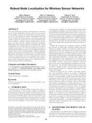
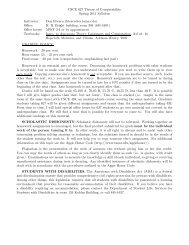
Figure 8: Deformation painting on a hand model.Figure 6: Moving the implicit tool toward the shape: the inner regionnever enters the shape.(a) (b) (c)(a)(b)(c)Figure 7: (a),(b) Moving an implicit tool through a sphere shape:no self-intersections occur. (c) Same shape as (b) but with cuttingplane.4.2 Deformation PaintingIn this modeling metaphor, the tool is moved along a path on thesurface of the shape. For this path, the surface is locally deformedinto or out of the shape. If the tool is at the location x s on the shapeat a certain time, we use r(x) = ‖x − x s ‖, r i = 0, and r o is interactivelychosen to steering the area of influence of the deformation.This means that the inner region is only the point x s for which weuse a constant v in the direction opposite to the surface normal ofx s . Figure 8 shows an example of deformation painting on a handmodel.4.3 Moving point setsIn this metaphor, we mark a number of points on the shape. Thesepoints may be isolated or located on a curve. Then we set r as asmooth approximated distance function to this point set, r i = 0, andr o is interactively chosen. Inside the inner region, a constant v isused. For the distance function to the point set, we used the approachdescribed in [Biswas and Shapiro 2004]. Figure 9 illustratesan example. The barycenter of all points is used as c. Note that inthis scenario the inner and the intermediate regions may consist ofmultiple unconnected parts.4.4 Collision tools and shape stampingIn this scenario, the tool is described by an arbitrary closed toolshape for which a repeated collision detection with the deformedshape is carried out. To do so, we used a bounding box hierarchybased approach implemented in [ColDet ]. <strong>Based</strong> on the detectedcollision points, r is constructed to be zero only in the areas ofcollision. Similar to moving points sets, we used a smooth approximateddistance function for r along with r i = 0. Inside the innerregion, v is constant for every time step, following the path of theinput device. Figures 10a,b illustrate the region function for thehand shape. Here, both the inner and the intermediate region consistof several unconnected parts. Figure 11 shows the deformationof the fan data set using the hand tool. Note that the sharp featuresare preserved under the deformation.Figure 9: Moving point sets: the inner region consist of two unconnectedparts close to the eyes of the bust.We also used this modeling metaphor for shape stamping: movingthe tool shape toward the deforming shape leaves the footprint onthe deforming shape. Figures 10c,d show an example stamping a Y-shaped tool shape onto a sphere. Figure 13 shows the deformationof the crater data set by using the Armadillo model as tool.4.5 Twisting and BendingUp to now, the vector field inside the inner region was constant.Now we apply linear and quadratic vector fields to get twisting andbending effects. For a twisting, r is linear and its gradient correspondsthe direction of the twisting axis. The point c is on thetwisting axis, and the rotational axis for the inner vector field coincideswith the twisting axis as well. Inside the inner region weuse a linearly increasing rotation defined by e(x) = (a (x − c) T ) 2 ,f (x) = (a×(x−c) T ) 2 . Figure 14 shows an extreme twisting of thebox model (51202 vertices) as well as a moderate twisting of thecamel model.To get a bending effect, we used the bending tool described in Figure4b. The region field r is linear and its gradient is perpendicularto the rotation axis. The thresholds r i ,r o are chosen such thatr(c) = 0.614r i + (1 − 0.614)r o . This choice comes from the definitionof the blending function: b(0.614) ≈ 1/2. During the bending,the gradient of r is changed with half the angle speed as the rotationin the inner region. Figure 15 gives an example. e(x) and f (x) describea rotation (Equation 7). Figure 1 shows some deformationsof the hand data. The result looks rather realistic, even though noskeletal hand model is involved. Figure 16 shows the bending ofthe Armadillo model.Figure 17 shows two shapes created from a sphere in an interactivesession by applying all modeling metaphors described above. Thesession time for each of the models was approximately 30 minutes.5 Implementational Details5.1 Integration with adaptive stepsizeDifferent approaches for a numerical stream/path line integrationhave been studied [Nielson et al. 1997], where higher order techniqueswith an adaptive stepsize turned out to have the best trade-
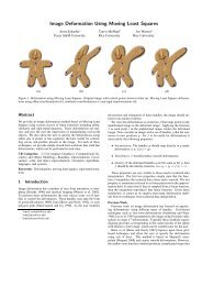
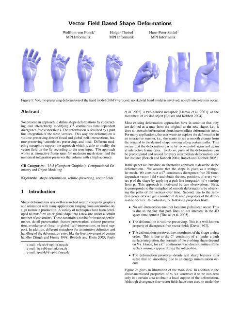
(a)(b)(a) (b) (c)(c)(f)(d)(e)Figure 16: Bending the Armadillo model.Figure 14: Twisting the box model: (a) placing the tool, (b)-(e)twisted models, (f) twisted camel.(a)(b)Figure 17: <strong>Shape</strong>s created from spheres in an interactive session.Figure 15: (a),(b) Bending a cylinder. (c) Box after bending.6 Evaluation and ComparisonIn this section we give an evaluation of our technique and compareit with other deformation approaches. We do so in terms of visualquality, other modeling metaphors, speed and accuracy.Visual quality: To get a comparison with existing techniques, weapply our technique to a number of standard test data sets for whichother deformation approaches have been reported in the literature.The twisting of a box (Figure 14) has been considered in [Yu et al.2004; Lipman et al. 2005; Zhou et al. 2005]. Our result shows thebehavior of a volume-preserving twisting even for an extreme deformation.The effect of bending a cylinder has been demonstratedfor different approaches in [Botsch and Kobbelt 2003; Botsch andKobbelt 2004; Zhou et al. 2005]. Our result (Figures 15a-b) shows arealistic looking bend without self intersections. Also, the bendingof the box (Figure 15c) and the deformation of the hand (Figure 1)look plausible and do not contain self-intersections. Furthermore,small scale features are deformed in a plausible manner (Figure 12).Other modeling metaphors: Our implicit tool metaphor using r asthe distance to a point (Figures 5, 7) is similar to the swirling sweepersmetaphor [Angelidis et al. 2004a]. However, our metaphor ismore flexible in the sense that other implicit functions can be used(Figure 6). Moreover, contrary to swirling sweepers our methoddoes not have to choose an appropriate number of basic swirls toapproximate the final deformation.Many modeling metaphors [Botsch and Kobbelt 2004; Sorkineet al. 2004; Botsch and Kobbelt 2005] work by setting areas of zerodeformation and areas of full deformation on the surface. Then thefull deformation is defined by a sequence of translations and rotations.Our tools have a similar metaphor, with the main differencethat we define the regions of zero and full deformation implicitly,i.e. by marking the underlying space. This may create problems inareas where surface parts of zero and full deformation are spatiallyclose to each other (for instance the fingers of a hand). For thesecases we use the cylinder tool (Figure 4b) and restrict the definitionto the area inside the cylinder.Speed: The performance of our approach depends on a number offactors: the number of vertices inside the inner region of the deformation,the number of vertices in the intermediate region, the chosenmodeling metaphor, and the chosen region field r. In general,vertices in the intermediate region are more expensive to integratethan vertices in the inner region because v has a more complicatedform there. Also, a simple r (such as the distance to a point in animplicit tool) gives a higher performance. Finally, for the metaphorof shape stamping, the additional collision-detections drops the performance.To get an evaluation of the performance of our approach,we consider a number of benchmark deformations. We placed animplicit tool describing the distance to a point in such a way thatno vertex of the shape is in the outer region (i.e., that all verticeshave to be integrated), and that most of the vertices are in the (mostexpensive) intermediate region. Then we applied a rather strongdeformation. Figure 19 shows the four benchmark deformations bythe initial and final shapes as well as used deformation tools. Here,the sphere-shaped intermediate region (green) has been cut out atthe black boundary lines. The following table shows the performanceon a AMD Opteron 152 (2.6 GHz) with 2 GB RAM anda GeForce 6800 GT GPU. There, #vert denotes the number of verticesof the model, #steps denotes the number of integration steps tocome from the original to the final shape, sps(CPU) gives the numberof integration steps per second for the CPU implementation,and sps(GPU) does so for the GPU implementation.model #vert #steps sps(CPU) sps(GPU)bust 30696 212.737 31.65260 292.2210hand 36619 186.194 26.94950 257.8860armadillo 172974 152.656 5.79448 61.8539dragon 437645 249.196 2.29102 27.2049It turns out that even for rather large meshes the deformations canbe carried out in an interactive manner. All the examples in theaccompanying video are captures from interactive sessions.Accuracy: The statement that our approach is volume-preservingholds only if every surface point of the shape undergoes an exactpath line integration. In reality, we carry out a numerical integrationonly for discrete surface points: the mesh vertices. Thus,slight changes of the volume during the deformation can be expected.However, the following table shows that they are minimaleven for strong deformations. Here, we measured the error
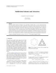
(a)(b)AcknowledgmentsFigure 18: Remeshing. (a) Mesh during deformation, (b) mesh afterdeformation and remeshing.(a) (b) (c) (d)The authors would like to thank Thomas Annen and Carsten Stollfor their advice on GPU programming. The Armadillo and Dragonmodels are courtesy of Stanford University. The Fandisk, Cameland Hand models are from the AIM@SHAPE shape repository.ReferencesALEXA, M. 2003. Differential coordinates for local mesh morphing and deformation.The Visual Computer 19, 2, 105–114.ALLIEZ, P., UCELLI, G., GOTSMAN, C., AND ATTENE, M. 2005. Recent Advancesin Remeshing of Surfaces. Springer.(e)(f)(g)(h)ANGELIDIS, A., CANI, M.-P., WYVILL, G., AND KING, S. 2004. Swirlingsweepers:Constant-volume modeling. In Computer Graphics and Applications,12th Pacific Conference on (PG’04), 10–15.ANGELIDIS, A., WYVILL, G., AND CANI, M.-P. 2004. Sweepers: Swept userdefinedtools for modeling by deformation. In Proceedings of <strong>Shape</strong> Modeling andApplications, IEEE, 63–73.AUBERT, F., AND BECHMANN, D. 1997. Volume-preserving space deformation.Comput. and Graphics 21, 5, 6125–639.Figure 19: Benchmark deformations. First line: original shapes andparts of tools. Second line: deformed shapes and parts of tools.as error =volume(deformed shape)volume(original shape) − 1.model orig. shape deformed shape errorsphere fig. 5a fig. 7b -0.001060box, twisted fig. 14a fig. 14d 0.000781box, bent fig. 14a fig. 15c 0.000751fan fig. 11a fig. 11c -0.000007armadillo fig. 16a fig. 16c 0.001344dragon fig. 19d fig. 19h -0.001520spider fig. 5a fig. 17a 0.001875own monster fig. 5a fig. 17b 0.000070BARR, A. 1984. Global and local deformations of solid primitives. In SIGGRAPH ’84:Proceedings of the 11th annual conference on Computer graphics and interactivetechniques, ACM Press, New York, NY, USA, 21–30.BENDELS, G. H., AND KLEIN, R. 2003. Mesh forging: editing of 3d-meshes usingimplicitly defined occluders. In SGP ’03: Proceedings of the 2003 Eurographics/ACMSIGGRAPH symposium on Geometry processing, Eurographics Association,Aire-la-Ville, Switzerland, Switzerland, 207–217.BISWAS, A., AND SHAPIRO, V. 2004. Approximate distance fields with nonvanishinggradients. Graphical Models 66, 3, 133–159.BOTSCH, M., AND KOBBELT, L. 2003. Multiresolution surface representation basedon displacement volumes. Computer Graphics Forum 22, 3, 483–491. (ProceedingsEurographics 2003).BOTSCH, M., AND KOBBELT, L. 2004. An intuitive framework for real-time freeformmodeling. ACM Trans. Graph. 23, 3, 630–634.BOTSCH, M., AND KOBBELT, L. 2005. Real-time shape editing using radial basisfunctions. Computer Graphics Forum 24, 3, 611–621. (Proceedings Eurographics2005).COLDET. Free 3D collision detection library. http://photoneffect.com/coldet.7 Conclusion and Future WorkIn this paper we introduced an alternative approach to shape deformations:by carrying out a path line integration of a time-dependentvector field for each shape vertex. This way, simple propertiesof the vector field lead to useful properties of the deformation: adivergence-free vector field gives a volume-preserving deformation,self-intersections cannot occur, and sharp features are preserved.Also small scale features are deformed realistically. Wehave also shown that the performance of the deformation sufficesfor real-time applications for moderately large meshes. The accuracyin volume-preserving is rather high.There is a number of issues for future research. First, the performancecan further be increased by a multi-processor parallelizationof the integration. This is possible because the integration of thevertices can be carried out independently of each other. Second,since the method does not rely on any connectivity information ofthe mesh, an application to point-based shape representations seemspossible. Finally, the modeling metaphor should be extended suchthat the regions of full and zero deformation can be marked explicitlyon the surface instead of implicitly in the embedding 3D space.COQUILLART, S. 1990. Extended free-form deformation: a sculpturing tool for 3dgeometric modeling. In SIGGRAPH ’90: Proceedings of the 17th annual conferenceon Computer graphics and interactive techniques, ACM Press, New York,NY, USA, 187–196.DAVIS, H. 1967. Introduction to vector analysis. Allyn and Bacon, Inc., Boston.DESBRUN, M., AND GASCUEL, M.-P. 1995. Animating soft substances with implicitsurfaces. In SIGGRAPH ’95: Proceedings of the 22nd annual conference onComputer graphics and interactive techniques, ACM Press, New York, NY, USA,287–290.FARIN, G. 2002. Curves and Surfaces for CAGD, 5th ed. Morgan Kaufmann, SanFrancisco.FOSTER, N., AND FEDKIW, R. 2001. Practical animation of liquids. In SIGGRAPH’01: Proceedings of the 28th annual conference on Computer graphics and interactivetechniques, ACM Press, New York, NY, USA, 23–30.GAIN, J. E., AND DODGSON, N. A. 1999. Adaptive refinement and decimation underfree-form deformation. Eurographics UK ’99.GAIN, J. E., AND DODGSON, N. A. 2001. Preventing self-intersection under freeformdeformation. IEEE Transactions on Visualization and Computer Graphics 7,4, 289–298.GUSKOV, I., SWELDENS, W., AND SCHRÖDER, P. 1999. Multiresolution signalprocessing for meshes. In SIGGRAPH ’99: Proceedings of the 26th annual conferenceon Computer graphics and interactive techniques, ACM Press/Addison-Wesley Publishing Co., New York, NY, USA, 325–334.
HIROTA, G., MAHESHWARI, R., AND LIN, M. 1992. Fast volume-preserving freeform deformation using multi-level optimization. In Proceedings Solid Modelingand applications, 234–245.HSU, W., HUGHES, J., AND KAUFMAN, H. 1992. Direct manipulation of free-formdeformations. In SIGGRAPH ’92: Proceedings of the 19th annual conference onComputer graphics and interactive techniques, ACM Press, New York, NY, USA,177–184.KOBBELT, L., CAMPAGNA, S., VORSATZ, J., AND SEIDEL, H.-P. 1998. Interactivemulti-resolution modeling on arbitrary meshes. In SIGGRAPH ’98: Proceedingsof the 25th annual conference on Computer graphics and interactive techniques,ACM Press, New York, NY, USA, 105–114.LIPMAN, Y., SORKINE, O., COHEN-OR, D., LEVIN, D., RÖSSL, C., AND SEIDEL,H.-P. 2004. Differential coordinates for interactive mesh editing. In Proceedingsof <strong>Shape</strong> Modeling International, IEEE Computer Society Press, 181–190.LIPMAN, Y., SORKINE, O., LEVIN, D., AND COHEN-OR, D. 2005. Linear rotationinvariantcoordinates for meshes. ACM Trans. Graph. 24, 3, 479–487.LLAMAS, I., KIM, B., GARGUS, J., ROSSIGNAC, J., AND SHAW, C. 2003. Twister:a space-warp operator for the two-handed editing of 3d shapes. ACM Trans. Graph.22, 3, 663–668.MACCRACKEN, R., AND JOY, K. 1996. Free-form deformations with lattices ofarbitrary topology. In SIGGRAPH ’96: Proceedings of the 23rd annual conferenceon Computer graphics and interactive techniques, ACM Press, New York, NY,USA, 181–188.MASON, D., AND WYVILL, G. 2001. Blendeforming: Ray traceable localizedfoldover-free space deformation. In CGI ’01: Proceedings of the InternationalConference on Computer Graphics, IEEE Computer Society, Washington, DC,USA, 183.NIELSON, G., HAGEN, H., AND MÜLLER, H. 1997. Scientific Visualization. IEEEComputer Society.PAULY, M., KEISER, R., KOBBELT, L., AND GROSS, M. 2003. <strong>Shape</strong> modeling withpoint-sampled geometry. ACM Trans. Graph. 22, 3, 641–650.RAPPOPORT, A., SHEFFER, A., AND BERCOVIER, M. 1996. Volume-preservingfree-form solids. IEEE Transactions on Visualization and Computer Graphics 2, 1,19–27.SEDERBERG, T., AND PARRY, S. 1986. Free-form deformation of solid geometricmodels. In SIGGRAPH ’86: Proceedings of the 13th annual conference onComputer graphics and interactive techniques, ACM Press, New York, NY, USA,151–160.SINGH, K., AND FIUME, E. 1998. Wires: a geometric deformation technique. InSIGGRAPH ’98: Proceedings of the 25th annual conference on Computer graphicsand interactive techniques, ACM Press, New York, NY, USA, 405–414.SORKINE, O., LIPMAN, Y., COHEN-OR, D., ALEXA, M., RÖSSL, C., AND SEIDEL,H.-P. 2004. Laplacian surface editing. In Proceedings of the Eurographics/ACMSIGGRAPH symposium on Geometry processing, Eurographics Association, 179–188.TAUBIN, G. 1995. A signal processing approach to fair surface design. In SIGGRAPH’95: Proceedings of the 22nd annual conference on Computer graphics and interactivetechniques, ACM Press, New York, NY, USA, 351–358.THEISEL, H., WEINKAUF, T., HEGE, H.-C., AND SEIDEL, H.-P. 2005. Topologicalmethods for 2D time-dependent vector fields based on stream lines and path lines.IEEE Transactions on Visualization and Computer Graphics 11, 4, 383–394.WELCH, W., AND WITKIN, A. 1992. Variational surface modeling. In SIGGRAPH’92: Proceedings of the 19th annual conference on Computer graphics and interactivetechniques, ACM Press, New York, NY, USA, 157–166.YU, Y., ZHOU, K., XU, D., SHI, X., BAO, H., GUO, B., AND SHUM, H.-Y. 2004.Mesh editing with poisson-based gradient field manipulation. ACM Trans. Graph.23, 3, 644–651.ZAYER, R., RÖSSL, C., KARNI, Z., AND SEIDEL, H.-P. 2005. Harmonic guidancefor surface deformation. In Computer Graphics Forum, Proceedings of Eurographics2005, Blackwell, Dublin, Ireland, vol. 24, Eurographics, 601–609.ZHOU, K., HUANG, J., SNYDER, J., LIU, X., BAO, H., GUO, B., AND SHUM, H.-Y.2005. Large mesh deformation using the volumetric graph laplacian. ACM Trans.Graph. 24, 3, 496–503.ZORIN, D., SCHRÖDER, P., AND SWELDENS, W. 1997. Interactive multiresolutionmesh editing. In SIGGRAPH ’97: Proceedings of the 24th annual conference onComputer graphics and interactive techniques, ACM Press/Addison-Wesley PublishingCo., New York, NY, USA, 259–268.8 AppendixGiven the C 2 continuous scalar fields e, f and the C 2 continuousregion field r with the thresholds r i ,r o , we show that v constructedby (2)–(5) is divergence-free and C 1 . The zero-divergence followsdirectly from (2) [Davis 1967]. For showing the C 1 continuity, wehave to consider the boundaries of the regions, i.e., the locations xwith r(x) = r i and r(x) = r o .For r(x) = r i , (5) givesb = 0 ,d bd r = 0 ,d 2 b= 0. (10)d r2 For b = b(r(x)), basic rules in differential calculus give∇b = d bd r ∇r ,To prove that v is C 1 , we have to showJ(∇b) = d bd r J(∇r) + d2 bd r 2 ∇r ∇rT . (11)∇e × ∇ f = ∇((1 − b) e) × ∇((1 − b) f ) (12)J(∇e × ∇ f ) = J(∇((1 − b) e) × ∇((1 − b) f )) (13)(2)–(4) give that the left-hand side of (12) describes v in the innerregion, while the right-hand side describes v in the intermediateregion. (13) does so for the Jacobian of v in inner and intermediateregion. Applying basic rules of differential calculus, we getand∇((1 − b) e) = (1 − b) · ∇e − e∇b (14)∇((1 − b) f ) = (1 − b) · ∇ f − f ∇b (15)J(∇((1 − b) e)) = (1 − b) J(∇e) − ∇e ∇b T− e J(∇b) − ∇b ∇e T (16)J(∇((1 − b) f )) = (1 − b) J(∇ f ) − ∇ f ∇b TInserting (10),(11) into (14),(15),(16),(17) we get− f J(∇b) − ∇b ∇ f T (17)∇((1 − b) e) = ∇e , ∇((1 − b) f ) = ∇ f (18)J(∇((1 − b) e)) = J(∇e) , J(∇((1 − b) f )) = J(∇ f )(19)which gives (12),(13). In fact, (18),(19) show that p and q definedin (3), (4) are C 2 across locations with r = r i .For r(x) = r o , (5) givesb = 1 ,To prove that v is C 1 , we have to showd b= 0. (20)d r∇((1 − b) e) × ∇((1 − b) f ) = 0 (21)J(∇((1 − b) e) × ∇((1 − b) f )) = 0 (22)where the left-hand side of (21) describes v in the intermediate regionand the right-hand side in the outer region. Inserting (11),(20)into (14), (15) gives (21). Inserting (11),(20) into (16), (17) togetherwith J(a × b) = J(a) × b + a × J(b) gives (22). It shows that at locationswith r = r o , p and q are only C 1 , whereas v is C 1 as well.The C 1 continuity of p and q is sufficient here because we have theadditional condition that v equals zero.Note that (14),(15) together with (11) and d d br = r 2ro −r ifrom (5) givesthe closed form of v if e, f ,r and their first order partials are given.