Vector Field Based Shape Deformations
Vector Field Based Shape Deformations
Vector Field Based Shape Deformations

Create successful ePaper yourself
Turn your PDF publications into a flip-book with our unique Google optimized e-Paper software.
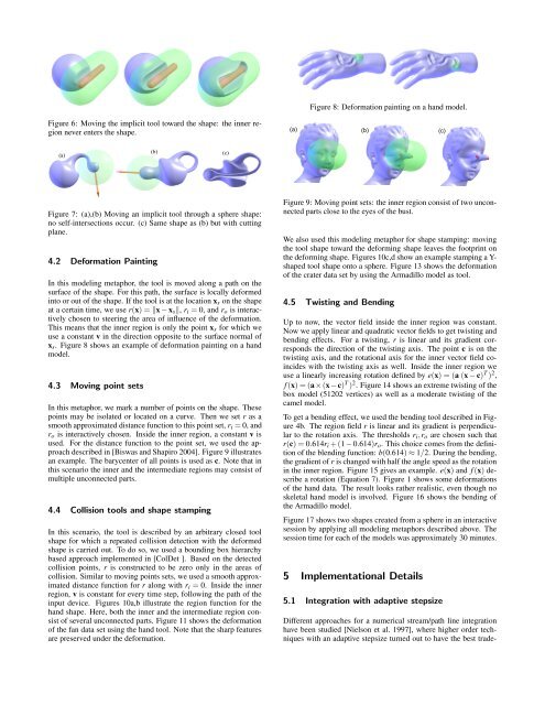
Figure 8: Deformation painting on a hand model.Figure 6: Moving the implicit tool toward the shape: the inner regionnever enters the shape.(a) (b) (c)(a)(b)(c)Figure 7: (a),(b) Moving an implicit tool through a sphere shape:no self-intersections occur. (c) Same shape as (b) but with cuttingplane.4.2 Deformation PaintingIn this modeling metaphor, the tool is moved along a path on thesurface of the shape. For this path, the surface is locally deformedinto or out of the shape. If the tool is at the location x s on the shapeat a certain time, we use r(x) = ‖x − x s ‖, r i = 0, and r o is interactivelychosen to steering the area of influence of the deformation.This means that the inner region is only the point x s for which weuse a constant v in the direction opposite to the surface normal ofx s . Figure 8 shows an example of deformation painting on a handmodel.4.3 Moving point setsIn this metaphor, we mark a number of points on the shape. Thesepoints may be isolated or located on a curve. Then we set r as asmooth approximated distance function to this point set, r i = 0, andr o is interactively chosen. Inside the inner region, a constant v isused. For the distance function to the point set, we used the approachdescribed in [Biswas and Shapiro 2004]. Figure 9 illustratesan example. The barycenter of all points is used as c. Note that inthis scenario the inner and the intermediate regions may consist ofmultiple unconnected parts.4.4 Collision tools and shape stampingIn this scenario, the tool is described by an arbitrary closed toolshape for which a repeated collision detection with the deformedshape is carried out. To do so, we used a bounding box hierarchybased approach implemented in [ColDet ]. <strong>Based</strong> on the detectedcollision points, r is constructed to be zero only in the areas ofcollision. Similar to moving points sets, we used a smooth approximateddistance function for r along with r i = 0. Inside the innerregion, v is constant for every time step, following the path of theinput device. Figures 10a,b illustrate the region function for thehand shape. Here, both the inner and the intermediate region consistof several unconnected parts. Figure 11 shows the deformationof the fan data set using the hand tool. Note that the sharp featuresare preserved under the deformation.Figure 9: Moving point sets: the inner region consist of two unconnectedparts close to the eyes of the bust.We also used this modeling metaphor for shape stamping: movingthe tool shape toward the deforming shape leaves the footprint onthe deforming shape. Figures 10c,d show an example stamping a Y-shaped tool shape onto a sphere. Figure 13 shows the deformationof the crater data set by using the Armadillo model as tool.4.5 Twisting and BendingUp to now, the vector field inside the inner region was constant.Now we apply linear and quadratic vector fields to get twisting andbending effects. For a twisting, r is linear and its gradient correspondsthe direction of the twisting axis. The point c is on thetwisting axis, and the rotational axis for the inner vector field coincideswith the twisting axis as well. Inside the inner region weuse a linearly increasing rotation defined by e(x) = (a (x − c) T ) 2 ,f (x) = (a×(x−c) T ) 2 . Figure 14 shows an extreme twisting of thebox model (51202 vertices) as well as a moderate twisting of thecamel model.To get a bending effect, we used the bending tool described in Figure4b. The region field r is linear and its gradient is perpendicularto the rotation axis. The thresholds r i ,r o are chosen such thatr(c) = 0.614r i + (1 − 0.614)r o . This choice comes from the definitionof the blending function: b(0.614) ≈ 1/2. During the bending,the gradient of r is changed with half the angle speed as the rotationin the inner region. Figure 15 gives an example. e(x) and f (x) describea rotation (Equation 7). Figure 1 shows some deformationsof the hand data. The result looks rather realistic, even though noskeletal hand model is involved. Figure 16 shows the bending ofthe Armadillo model.Figure 17 shows two shapes created from a sphere in an interactivesession by applying all modeling metaphors described above. Thesession time for each of the models was approximately 30 minutes.5 Implementational Details5.1 Integration with adaptive stepsizeDifferent approaches for a numerical stream/path line integrationhave been studied [Nielson et al. 1997], where higher order techniqueswith an adaptive stepsize turned out to have the best trade-