Vector Field Based Shape Deformations
Vector Field Based Shape Deformations
Vector Field Based Shape Deformations

You also want an ePaper? Increase the reach of your titles
YUMPU automatically turns print PDFs into web optimized ePapers that Google loves.
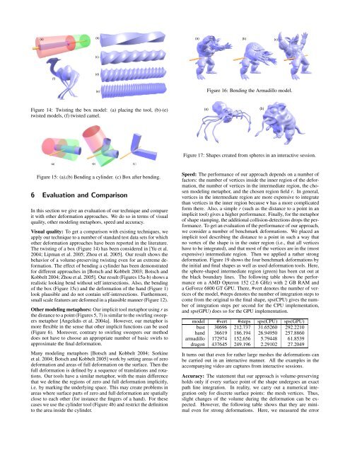
(a)(b)(a) (b) (c)(c)(f)(d)(e)Figure 16: Bending the Armadillo model.Figure 14: Twisting the box model: (a) placing the tool, (b)-(e)twisted models, (f) twisted camel.(a)(b)Figure 17: <strong>Shape</strong>s created from spheres in an interactive session.Figure 15: (a),(b) Bending a cylinder. (c) Box after bending.6 Evaluation and ComparisonIn this section we give an evaluation of our technique and compareit with other deformation approaches. We do so in terms of visualquality, other modeling metaphors, speed and accuracy.Visual quality: To get a comparison with existing techniques, weapply our technique to a number of standard test data sets for whichother deformation approaches have been reported in the literature.The twisting of a box (Figure 14) has been considered in [Yu et al.2004; Lipman et al. 2005; Zhou et al. 2005]. Our result shows thebehavior of a volume-preserving twisting even for an extreme deformation.The effect of bending a cylinder has been demonstratedfor different approaches in [Botsch and Kobbelt 2003; Botsch andKobbelt 2004; Zhou et al. 2005]. Our result (Figures 15a-b) shows arealistic looking bend without self intersections. Also, the bendingof the box (Figure 15c) and the deformation of the hand (Figure 1)look plausible and do not contain self-intersections. Furthermore,small scale features are deformed in a plausible manner (Figure 12).Other modeling metaphors: Our implicit tool metaphor using r asthe distance to a point (Figures 5, 7) is similar to the swirling sweepersmetaphor [Angelidis et al. 2004a]. However, our metaphor ismore flexible in the sense that other implicit functions can be used(Figure 6). Moreover, contrary to swirling sweepers our methoddoes not have to choose an appropriate number of basic swirls toapproximate the final deformation.Many modeling metaphors [Botsch and Kobbelt 2004; Sorkineet al. 2004; Botsch and Kobbelt 2005] work by setting areas of zerodeformation and areas of full deformation on the surface. Then thefull deformation is defined by a sequence of translations and rotations.Our tools have a similar metaphor, with the main differencethat we define the regions of zero and full deformation implicitly,i.e. by marking the underlying space. This may create problems inareas where surface parts of zero and full deformation are spatiallyclose to each other (for instance the fingers of a hand). For thesecases we use the cylinder tool (Figure 4b) and restrict the definitionto the area inside the cylinder.Speed: The performance of our approach depends on a number offactors: the number of vertices inside the inner region of the deformation,the number of vertices in the intermediate region, the chosenmodeling metaphor, and the chosen region field r. In general,vertices in the intermediate region are more expensive to integratethan vertices in the inner region because v has a more complicatedform there. Also, a simple r (such as the distance to a point in animplicit tool) gives a higher performance. Finally, for the metaphorof shape stamping, the additional collision-detections drops the performance.To get an evaluation of the performance of our approach,we consider a number of benchmark deformations. We placed animplicit tool describing the distance to a point in such a way thatno vertex of the shape is in the outer region (i.e., that all verticeshave to be integrated), and that most of the vertices are in the (mostexpensive) intermediate region. Then we applied a rather strongdeformation. Figure 19 shows the four benchmark deformations bythe initial and final shapes as well as used deformation tools. Here,the sphere-shaped intermediate region (green) has been cut out atthe black boundary lines. The following table shows the performanceon a AMD Opteron 152 (2.6 GHz) with 2 GB RAM anda GeForce 6800 GT GPU. There, #vert denotes the number of verticesof the model, #steps denotes the number of integration steps tocome from the original to the final shape, sps(CPU) gives the numberof integration steps per second for the CPU implementation,and sps(GPU) does so for the GPU implementation.model #vert #steps sps(CPU) sps(GPU)bust 30696 212.737 31.65260 292.2210hand 36619 186.194 26.94950 257.8860armadillo 172974 152.656 5.79448 61.8539dragon 437645 249.196 2.29102 27.2049It turns out that even for rather large meshes the deformations canbe carried out in an interactive manner. All the examples in theaccompanying video are captures from interactive sessions.Accuracy: The statement that our approach is volume-preservingholds only if every surface point of the shape undergoes an exactpath line integration. In reality, we carry out a numerical integrationonly for discrete surface points: the mesh vertices. Thus,slight changes of the volume during the deformation can be expected.However, the following table shows that they are minimaleven for strong deformations. Here, we measured the error