AIRSTACK - Multistack
AIRSTACK - Multistack
AIRSTACK - Multistack
- No tags were found...

Create successful ePaper yourself
Turn your PDF publications into a flip-book with our unique Google optimized e-Paper software.
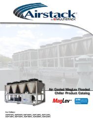
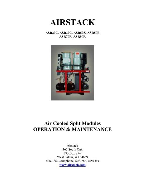
<strong>AIRSTACK</strong>ASR20C, ASR30C, ASR50Z, ASR50BASR70R, ASR90RAir Cooled Split ModulesOPERATION & MAINTENANCEAirstack365 South OakPO Box 854West Salem, WI 54669608-786-3400 phone 608-786-3450 faxwww.airstack.com
Table of Contents1.0 Chiller Identification………………………………………….…………….31.1 Air Cooled Split Model Number……………………….…….……..31.2 Serial Number……………………….………………………………32.0 Theory of Operation…………………………………………………………43.0 Daily Log Sheet………………………………………………………………44.0 Pressure Readings…………………………………………………………….45.0 Strainer Cleaning…………………………………………………….…………..56.0 Oil Level…………………………………………………………….……………57.0 Refrigerant Charge / Evacuation…………………………………….……………58.0 Filter Driers………………………………………………………….……………69.0 Superheat / Subcooling…………………………………………..……………….610.0 Pressure Relief Valve………………………………………………..……………611.0 Annual Maintenance………………………………………………………………612.0 Compressors………………………………………………………….…………..713.0 Heat Exchangers…………………………………………………………………714.0 Troubleshooting Air Cooled Split Modules………………..........…..…………..815.0 Daily Log Sheet……………………………………………………………… ..9
1.0 Chiller IdentificationThe module data plate which contains the model and serial number for all ASR modulesis located on the “B” side electrical box door of each module.1.1 Air Cooled Split Model NumberASR30C5H2W-VASR = Airstack Remote30 = tons 20,30,50,70,90 = tonsC = Trane Scroll Compressor Z = Copeland Scroll R = Copeland ScrewB = Bristol Recip. T = Turbocor Centrifugal5 = dual evaporators 1 = single evap std. efficiency2 = single evap high efficiency 4 = dual evap std. efficiency6 = dual evap high efficiencyH = 460V A = 208V L = 230V C = 575V V = special2 = wired as multiple module 1 = wired as single modulA = air cooledV = variation (* if noted)1.2 Serial Number IdentificationJC-06-25J = --0- (decade built) I = 1990’s J= 2000’sC = ---3 (year built) A= ’01 B= ’02 ………………………….06 = June (month built) 01 = Jan. 02 = Feb. ………………………….25 = 25 th module built 01 = 1 st 02 = 2 nd …………………………..
2.0 Theory of OperationThe Airstack chiller provides chilled water to an external load based off of thereturn water temperature to the Airstack master control. When the EnteringChilled Water sensor sends the signal to the master control that cooling is needed,compressors will begin to start and produce chilled water. The point at which theECHW temperature calls for compressors to start is determined by the Upsetpointand the Variable Set-point setting in the system variables menu of themaster control.When the ECHW sensor senses that the chilled water temperature has droppedbelow the set-point, compressors will begin to cycle off.3.0 Daily Log SheetOn the back page of this manual is a chiller information log sheet. The log sheetcan be used daily, weekly or as desired to record operation characteristics of thechiller. The information recorded on the log sheet can also be very helpful fordiagnosing potential problems in the system.4.0 Pressure ReadingsThe operating suction and discharge pressures in the system are directly related towater flow, condenser temperatures, chilled water set-points, and the cleanlinessof the system.For a R22 chiller at standard Air-cooled conditions of 55º ECHW, 45º LCHW,95º Ambient, 125º Condensing the suction pressure should be approximately 64psig and the discharge pressure 275 psigAll ASR modules have a high pressure cut out safety device. The HP cut out foran ASR modules is 320 psig for R-22, and 340 psig for R-407C.Each ASP module also has a low pressure safety device. The LP cut out forR-22, R-407C, or R-134a is 25 psig.A LP fault is an indication of low refrigerant charge in the system. If a circuit isgoing out on a LP fault check the static pressure of the system while the circuit isin the off mode. If pressures are low check the circuit for possible leaks. Thecircuit can be pressurized to 15 psig with refrigerant and topped to 160 psig withdry Nitrogen.
5.0 Strainer CleaningAll Airstack modules have a 30 mesh filter cartridge in the evaporator inletheader. The purpose for the filter cartridge is to keep debris from entering theheat exchanger. An external “Y” or basket type system strainer should also beinstalled as a pre-filter to the factory supplied strainers.There is no set time for cleaning the filter cartridges. The frequency of thisprocess is dependant on the water quality in the evaporator loop.Normally, debris in a water loop is going to take the path of least resistance andbuild up on the last modules to receive water.If circuits are faulting on Low Suction Temperature, or Low Chilled WaterTemperature the chilled water inlet filter cartridge should be checked. Thestrainers are located in the top header on the CHW side. If the strainers are cleanthe fault is most likely being caused by a low flow condition or to low of setpointsin the master control. If these possibilities are eliminated the evaporatorheat exchangers may need cleaning.6.0 Compressor Oil LevelAll compressors used on ASR modules have an oil level sight glass on eachcompressor. Oil level on ASR modules is not set at the factory. Once the systemis up and running in the field the above mentioned levels should be followed. Onsystems with over 50’ length run to the condenser oil may need to be addedFollowing are the oil level recommendations.Scroll, and Reciprocating Compressors are all 1 stage and oil level should be at1/8 – ¼ full sight glass.Screw compressors have 3 steps of capacity. At 100% the oil level should be 3/4– 7/8 full.Factory oil charge volume for each compressor can be found in the Product DataCatalog.7.0 Refrigerant Charge / EvacuationASR modules are also evacuated to a maximum of 150 microns and held 15minutes. ASR modules are then given a Nitrogen holding charge for shipping.The proper refrigerant charge for each module can be found on the module dataplate.
On air cooled machines the proper charging procedure is by a calculated weigh inmethod. Charging to a full sight glass on air cooled machines will likely result inover charging as the elbows in the liquid line as well as the liquid line solenoidvalve still produce some flashing even with the correct charge. As fans arecycling the sight glass will also display some bubbling.8.0 Filter DriersASR modules have longer refrigerant pipe runs and higher refrigerant charges.These modules are built with a factory installed liquid line filter drier. The filterdriers are a solid core sweat fitting replaceable type. In the case of a compressormotor burn or water contamination in the system, it is recommended to also installa suction filter drier.9.0 Superheat / SubcoolingAirstack uses a mechanical type expansion valve on all modules. By turning thevalve adjustment clockwise superheat is increased.ASR modules will need to have the superheat set in the field during start up. 10 –12 degrees is also the desired setting.Subcooling is necessary in the system to prevent flash gas as the refrigerant entersthe expansion valve. Airstack condensers are sized so that subcooling of theliquid refrigerant will take place with no separate subcooler being needed. Thegeneral range of subcooling seen is 7- 15 degrees.10.0 Pressure Relief ValveA 400 psig pressure relief valve is standard with all ASR modules The reliefvalve is installed on the receiver and has a 5/8” flare connection.11.0 Annual MaintenanceMost of the annual maintenance requirements for Airstack Chillers involve propershut-down of the machine, and cleaning of the heat exchangers.Preventative Maintenace bulletin #021594PM and Heat Exchanger CleaningProcedures bulletin #091594CP describe the recommended procedures for bothprocesses. Airstack has available the 151A Cleaning Kit to assist with thisprocess. Please see the 151A Cleaning Kit bulletin # 090195CK for more details.All of these bulletins are part of the standard O&M manual package.
Other annual checks that should be done:A check of all electrical components (contactors, fuses, relays, etc..)should be performed once a year for any signs of excessive wear.Checking for tight connections should also be performed at this time.Superheat, pressure gauges, oil levels, master control condition, andsensor accuracy should also be checked.12.0 CompressorsWith any chiller system there is always the chance of a compressor failure. In theevent of a failure, proper steps should be taken to determine the cause of thefailure.A motor burn due to a fault in the motor insulation is quite rare. Most burnoutsare actually caused by a mechanical condition or lubrication problems. In theevent of a burnout, proper clean up procedures should be followed.1. Check all electrical components of the circuit (contactors, fuses, wires,etc.)2. If necessary do a system clean up. Nu-Calgon RX-11 flush, or SporlanSystem Cleaner work well.3. Install a suction filter drier with burnout core. See section 7 on filterdriers.4. Evacuate the system to a minimum of 500 microns and hold for 20minutes.5. Charge the circuit with virgin refrigerant. Charge with liquid into thedischarge side. See refrigerant charge on nameplate data of unit.6. Run the system 2-3 weeks with burnout filter core. Replace withstandard core drier.13.0 Heat ExchangersAirstack uses brazed plate stainless steel heat exchangers for all evaporators.Without proper water treatment or due to abuse, heat exchangers can corrode overtime and eventually develop an internal leak. In such an event it would becomenecessary to replace the heat exchanger.Following are the step’s for field replacement of a failed evaporator heatexchanger.
1. If the refrigerant has not been lost on the failed circuit, you should firstdo a standard refrigerant recovery.2. Begin by isolating the chiller and draining water from the evaporators..3. Remove the 6” water header pipes by unbolting the victauliccouplings.4. Support the underneath of the defective heat exchanger and the othercircuit heat exchanger if applicable. A 2x4 and 1x4 should fit perfectlyunderneath.5. Using a saws all you can now cut the refrigerant piping to remove theheat exchanger. Cut on the bottom side of the elbow and sweat offremaining portion of old elbow.6. Remove the red support brace that holds both heat exchangers in place.Once this is removed you can remove the defective exchanger.7. Set the new heat exchanger in place and re-install the support brace.8. Fit the couplings and refrigerant piping into the heat exchanger. Youmay need to loosen the rotolock at the compressor at this time.9. Braze in the new exchanger while purging with a low pressure ofnitrogen.10. After brazing leak check and evacuate to a maximum of 500 microns.Charge the circuit according to the name plate charge.If the heat exchanger failure has caused water to enter into the refrigerant side, thecompressor and split condenser should also be checked for possiblecontamination. If water has entered into the compressor it is recommended thecompressor be replaced, as removing all the moisture from the oil is very difficult.Replacement of the expansion valve, and installation of a suction drier with awater core cartridge is also recommended.Evacuate the circuit to a maximum of 500 microns and let stand for 20 minutes.Charge the circuit and run 2-3 weeks with the high water core cartridge and thenreplace with a standard core.14.0 Troubleshooting Air Cooled Split ModulesFor ASR modules, please see the Troubleshooting Guide on page 15 of theComput 25 User Manual located in section 6 of the O&M package.
lll MULTISTACKCHILLERDAILY LOG SHEETDATEComp #1Comp #2Comp #3Comp #4Comp #5Comp #6Comp #7Comp #8Comp #9Comp #10Comp # 11Comp #12SystemSystemStatus Suct. Press Head Press Suct. Temp LoChw Temp Fault (if any)Ent. Chw Lvg. Chw Ent CW Lvg. CW Demand CapacityUpset Loset VSP Load Limit Tdiff IndexCOMMENTS: CHW P Drop . CW P Drop .