Switch Mode Power Supply (SMPS) Topologies (Part II) - Microchip
Switch Mode Power Supply (SMPS) Topologies (Part II) - Microchip
Switch Mode Power Supply (SMPS) Topologies (Part II) - Microchip
- No tags were found...

Create successful ePaper yourself
Turn your PDF publications into a flip-book with our unique Google optimized e-Paper software.
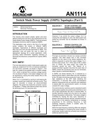
AN1207FIGURE 40:HALF-BRIDGE CONVERTER WAVEFORMS: SECONDARY SIDEQ1 Commandt(A)Q2 Commandt(B)NP/NS VDC/2VS-NS/NP VDC/2NS/NP VDCVD3tt(C)(D)ID3t(E)VD4t(F)ID4t(G)VLt(H)IO, av, nomILt(I)(A) = Command signal on Q1 MOSFET gate(B) = Command signal on Q2 MOSFET gate(C) = Voltage V S on secondary winding NS(D) = Voltage on diode D3(E) = Current flowing in diode D3(F) = Voltage on diode D4(G) = Current flowing in diode D4(H) = Voltage on inductor LO(I) = Current in inductor LODS01207B-page 44© 2009 <strong>Microchip</strong> Technology Inc.