Model View Definition (MVD) Format - buildingSMART⢠Singapore
Model View Definition (MVD) Format - buildingSMART⢠Singapore
Model View Definition (MVD) Format - buildingSMART⢠Singapore
- No tags were found...

Create successful ePaper yourself
Turn your PDF publications into a flip-book with our unique Google optimized e-Paper software.
IFC <strong>Model</strong> <strong>View</strong> <strong>Definition</strong> <strong>Format</strong>Author Jiri HietanenDate 08.04.2006Version 1.0Status FinalHistory 04.04.2006 – Officially accepted by IAI ITM07.04.2006 – Officially accepted by IAI IC08.04.2006 – Final versionCopyright Copyright © 2006 International Alliance for InteroperabilityTable of contentsExecutive summary ......................................................................................2Acknowledgements ......................................................................................3Background ..................................................................................................4The larger picture......................................................................................4Re-using definitions ..................................................................................6<strong>Definition</strong>s and configurations...................................................................7Patterns ....................................................................................................9Extensibility...............................................................................................9Partial use of the format..........................................................................10Implementers agreements ......................................................................10Quality control.........................................................................................11The role of IAI .........................................................................................12Lifecycle of IFC <strong>Model</strong> <strong>View</strong> <strong>Definition</strong>s..................................................13Process of creating IFC <strong>Model</strong> <strong>View</strong> <strong>Definition</strong>s .....................................14Roadmap for IFC <strong>Model</strong> <strong>View</strong> <strong>Definition</strong> work ........................................14IFC <strong>Model</strong> <strong>View</strong> <strong>Definition</strong> format ...............................................................16Overview.................................................................................................16Concepts.................................................................................................17Documents..............................................................................................18Diagrams ................................................................................................22
IFC <strong>Model</strong> <strong>View</strong> <strong>Definition</strong> <strong>Format</strong> Page 2 of 25Executive summaryTraditionally IFC <strong>Model</strong> <strong>View</strong> <strong>Definition</strong>s have been understood as subsets ofthe IFC <strong>Model</strong> Specification and have been defined primarily for IFC implementationpurposes. The format defined in this document covers the samescope. However, it is important to understand the connections it has to a largerpicture (IDM 1 ), in which requirements come from the value chain of theend user and the primary role of IFC <strong>Model</strong> <strong>View</strong> <strong>Definition</strong>s is to ensure thatIFC implementations support those requirements.For definition of IFC <strong>Model</strong> <strong>View</strong>s the goal was set to “finding a useful balancebetween the wishes of users/customers and the possibilities of software developers,and documenting the outcome clearly.” The IFC <strong>Model</strong> <strong>View</strong> <strong>Definition</strong><strong>Format</strong> is used for documenting this outcome.The format must be well defined and unambiguous, but the format is only onepart of what is needed.• <strong>Format</strong>: The type of data that needs to be captured and how that datais structured• Content: The data that is needed in a specific case. For example theIFC Schema is content that is captured using the EXPRESS format andan IFC <strong>Model</strong> <strong>View</strong> <strong>Definition</strong> is content that is captured using the IFC<strong>Model</strong> <strong>View</strong> <strong>Definition</strong> format.• Process: The roles and responsibilities of different involved parties, forexample how a model view definition becomes official and how certificationis organized.• Tools: The tools used for creating content, e.g. Process Maps and ExchangeRequirements, and managing the process of creating content.Tools are highly important, but the format itself must be independentfrom any specific tools.Although the format is in theory independent from the other parts it must inpractice support all of them. It is also clear that the format is not the full answer,but having a commonly agreed format is the starting point. Without acommon format it is very difficult to reuse content and tools, or to define aclear process.For the process defining the role of IAI is the most important single factor. Thisis largely a question of resources IAI has at its disposal and how those resourcesare applied.This is the first version of the official format, and it is to be expected that somedetails have to be adjusted later. However, the ideas behind this format havebeen thought out very carefully and should be stable. This format is based onthe IFC <strong>Model</strong> <strong>View</strong> <strong>Definition</strong> and related formats developed by the BLIS 2 ,ProIT 3 and IDM 4 projects and it has been developed and validated by thepeople behind these efforts.1 Information Delivery Manual2 http://www.blis-project.org3 http://virtual.vtt.fi/proitCopyright © 2006 International Alliance for Interoperability
IFC <strong>Model</strong> <strong>View</strong> <strong>Definition</strong> <strong>Format</strong> Page 3 of 25AcknowledgementsA large number of people and organizations have contributed to the content ofthis document. In general this document does not present anything groundbreakingor completely new. The work can rather be characterized as an attemptto harmonize and connect different ideas and efforts related to the implementationof the IFC <strong>Model</strong> Specification and the practical use of such implementations.Anyone active in this area has contributed in one way or another,especially people involved in BLIS, ProIT, IDM and IFC implementationgroups.The work on this official IFC <strong>Model</strong> <strong>View</strong> <strong>Definition</strong> format was initiated by aproposal from BLIS at ITM Summit #29 in Madrid, February 2005. That proposaland all subsequent work by the author were made possible throughfunding from the Finnish VBE2 project. In the first stage Kari Karstila and JeffWix contributed to the harmonization work between the approaches of BLIS,ProIT and IDM. Later also Janne Marit Aas-Jakobsen, Kjetil Espedokken, OleKristian Kvarsvik and Sakari Lehtinen had a major impact on the outcome ofthis work. As a result of this harmonization the format has been improved toenable a much stronger end user focus than was originally envisioned. Valuablefeedback was received from discussions with Vladimir Bazjanac, ChuckEastman, Kent Reed and Richard See from IAI TAG. In addition a large numberof people participated actively in related meetings, online training sessionsand presentations, creating and refining the material that is used in this document.Make everything as simple as possible,but not any simpler.- Albert Einstein -4 http://idm.buildingsmart.noCopyright © 2006 International Alliance for Interoperability
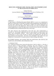
IFC <strong>Model</strong> <strong>View</strong> <strong>Definition</strong> <strong>Format</strong> Page 4 of 25BackgroundThe larger pictureProcess MapExchange RequirementsIFC ImplementationsIFC <strong>Model</strong> <strong>View</strong> <strong>Definition</strong>sIFC <strong>Model</strong> SpecificationFigure 1 Steps required for reaching deployment of IFC based solutions 5The figure above shows the different steps that are needed for creating IFCbased interoperable solutions that are successfully deployed in AEC/FM projects.It is like a ‘task list’ for all the things that must be taken care of. The pictureis shaped like a pyramid, because the shortcomings of any level limit thepossibilities of the levels above it.• IFC <strong>Model</strong> Specification is the IFC schema and its documentation• IFC <strong>Model</strong> <strong>View</strong> <strong>Definition</strong>s document how the IFC <strong>Model</strong> Specificationis applied in the data exchange between different application types.• IFC Implementations are the IFC import and export capabilities ofsoftware applications• Exchange Requirements document the information that must bepassed from one business process to enable another to happen.• Process Map gives and overview of the end user process, describingits objective and describes the stages in a project at which the processis expected to be relevant.Process MapExchange RequirementsIFC ImplementationsIFC <strong>Model</strong> <strong>View</strong> <strong>Definition</strong>sIFC <strong>Model</strong> SpecificationCreating newpossibilitiesMaking use of thenew possibilitiesRequired technical skillsNumber of peopleinvolvedInternational / genericLocal / specificCentral controlFigure 2 General trendsIt is important to identify some general trends related to the larger picture. Ingeneral lower levels are creating new possibilities for the levels above them.For this effort to be successful there has to be demand on the higher levels for5 Based on ”The Interoperability Pyramid” (Hietanen, 2003)Copyright © 2006 International Alliance for Interoperability
IFC <strong>Model</strong> <strong>View</strong> <strong>Definition</strong> <strong>Format</strong> Page 5 of 25such new possibilities. In this sense all efforts should ultimately be driven bythe requirements of deployment; without deployment the whole system has noreason to exist. But of course there are technological innovations, which nobodycan really demand before they exist. In such cases the lower levels haveto take a risk and assume that such new possibilities will eventually be acceptedand deployed. Because of these dynamics each level needs to be inactive dialog with at least the levels directly below and above. The formatsand methodologies used must facilitate this dialog. For example the end resultof software certification must enable software users to understand the possibilitiesand limitations of different software in IFC based data exchange. Onthe other side software implementers must understand the IFC <strong>Model</strong> <strong>View</strong><strong>Definition</strong>s on which their IFC implementations are based, but they should notbe required to know the whole IFC <strong>Model</strong> Specification.The number of people involved will increase dramatically when IFC based interoperabilitybecomes standard practice. Because of this it is important tobuild a system, in which the required level of technical skills decreases proportionallywhenever the number of people increases. This may be as dramaticas having a dozen people working on the IFC <strong>Model</strong> Specification andseveral million in deployment. The success of deployment can not be allowedto be directly dependent on a small group of IFC experts.The IFC <strong>Model</strong> Specification is an international standard and construction activityis by nature local. Somewhere in between a transition from internationalto local has to take place. Software is increasingly international and IFC <strong>Model</strong><strong>View</strong> <strong>Definition</strong>s, which sit between the IFC <strong>Model</strong> Specification and IFC Implementations,are by this logic also international. Of course software is localizedto specific markets and there is still a large number of purely local software.Exchange Requirements are much closer to local processes, includingdesign contracts, but contain many universal elements. One major challengeis creating a system, which allows generic, internationally applicable solutionsto be successfully reused and applied in specific local situations.It is also natural that any central control gets weaker closer to deployment.The IFC <strong>Model</strong> Specification can be carried out as a centralized internationaleffort and official software certification can at least be facilitated and controlledby the IAI. After that IAI International may at best have an unofficial role in e.g.creating guidelines or documenting and publishing experiences and best practices.On the higher levels standardization of the Information Delivery Manual is togive the end users of a BIM a set of quality assured IDMs to pick from whenmodeling the localized company or project specific building or FM process.The standardization needs therefore to be both at the international level, witha core of international acceptable contracts of data interchange, and at thenational level, where national requirements are built into the set of IDMs.Copyright © 2006 International Alliance for Interoperability
IFC <strong>Model</strong> <strong>View</strong> <strong>Definition</strong> <strong>Format</strong> Page 6 of 25Not IFCProcess MapNot IFCDefining the processes thatthe end user is running in aprojectNot IFCExchange RequirementsNot IFCThe defined scope of dataexchange in a businessprocessIFC ImplementationsThe actual range ofpossibilities available in IFCbased data exchangeIFC <strong>Model</strong> <strong>View</strong> <strong>Definition</strong>sThe defined range ofpossibilities available in IFCbased data exchangeIFC <strong>Model</strong> SpecificationFigure 3 Defined and actual possibilitiesIt is important to understand the role of IFC Implementations, because it isslightly different from the other layers. It is relatively easy to define the datathat must be exchanged in a business process and how the IFC <strong>Model</strong> Specificationshould be used for exchanging the required data. But this data cannotbe exchanged using IFCs before the corresponding capabilities and IFC implementationsexist in software. IFC implementations also have to reach acertain level of robustness and general usability before they are accepted bythe majority of users. From this perspective IFC implementations define whatcan really be done with IFC based data exchange at any given point in time.Exchange Requirements may however define data which is outside the scopeof existing IFC implementations. In such cases the Exchange Requirementserves as a requirements definition for future IFC <strong>Model</strong> <strong>View</strong> <strong>Definition</strong>s,software development and IFC implementations. In the mean time such partsof Exchange Requirements have to be satisfied with other solutions than IFCbased data exchange.Re-using definitionsThe ability to reuse definitions is one of the major goals of the IFC <strong>Model</strong> <strong>View</strong><strong>Definition</strong> format. The main enabling mechanism is concepts. All advancedview definition formats follow this idea; in ProIT they are called “aspects”, inIDM “functional parts” and “units of functionality” by ISG.Concepts are independent from any IFC <strong>Model</strong> <strong>View</strong> <strong>Definition</strong>. Technically anIFC <strong>Model</strong> <strong>View</strong> <strong>Definition</strong> is created by choosing (or defining) a group of conceptsand defining their relationships. For example a “rectangular profile” conceptcould be selected into an IFC <strong>Model</strong> <strong>View</strong> <strong>Definition</strong>, but defined to onlybe used with beams and columns, not spaces and walls.One form of re-use is to separate the idea of a concept (blue) from the IFCbinding of that concept (orange). This makes it possible to re-use the sameconcept ideas when the underlying IFC <strong>Model</strong> Specification changes. For examplethe idea of a “space name” does not change if moved at some pointfrom IfcSpace.LongName to some other location in the IFC <strong>Model</strong> Specification.Although not a part of any official format, software tools are highly importantfor re-using definitions. The format defines a system which makes it possibleto re-use definitions, but tools can make it much easier to know what has al-Copyright © 2006 International Alliance for Interoperability
IFC <strong>Model</strong> <strong>View</strong> <strong>Definition</strong> <strong>Format</strong> Page 7 of 25ready been defined. Tools also help share the definitions with large groupsmaking it less likely that the same definitions are reinvented.<strong>Definition</strong>s and configurationsThe IFC <strong>Model</strong> <strong>View</strong> <strong>Definition</strong> format makes extensive use of two very generalideas; definitions and configurations. <strong>Definition</strong>s capture a range of possibilitiesand configurations capture how those possibilities are used in a specificcase. There can be many different configurations for any definition, becausethe same possibilities may be used in different ways in different situations.<strong>Definition</strong>ConfigurationAdditional defintionsFigure 4 <strong>Definition</strong>s and configurationsA configuration does two things; first it defines a subset of the available possibilities,then it defines in more detail how that subset is used. Configurationsreduce scope, but are more specific about how the remaining scope is used.Additional definitions may not be in conflict with the original definition and it isnot possible to extend the scope of the original definition with configurations.Each IFC <strong>Model</strong> <strong>View</strong> <strong>Definition</strong> is a configuration of the IFC <strong>Model</strong> Specification.They define a subset of the IFC <strong>Model</strong> Specification and add new definitions,called implementers agreements, to it. The end results of software certificationare software specific configurations of the IFC <strong>Model</strong> <strong>View</strong> <strong>Definition</strong>on which the certification was based. Software may not support the full scopeof an IFC <strong>Model</strong> <strong>View</strong> <strong>Definition</strong> and often there is need for additional definitions,e.g. that imperial units are converted and imported as metric or sometype of geometry is imported in a simplified form.Configuration#1Configuration#2SameDifferentFigure 5 Comparing configurations of the same definitionIt is possible to compare configurations of the same definition. If the definitionsand configurations are documented using a computer interpretable format(schema) it is possible to use software for such comparisons.Copyright © 2006 International Alliance for Interoperability
IFC <strong>Model</strong> <strong>View</strong> <strong>Definition</strong> <strong>Format</strong> Page 8 of 25Process MapExchange Requirement 1.1(Configuration of 1)Exchange Requirement 1.2(Configuration of 1)1 = all concepts used in 1.1 and 1.2(<strong>Definition</strong>)May define data thatis not exchangedthrough IFCsIFC <strong>Model</strong> <strong>View</strong> <strong>Definition</strong> A(Configuration of 1)IFC Binding of A(<strong>Definition</strong>)Software N support of A(Configuration of A > 1)Software Certificationfor ADefines only datathat is exchangedthrough IFCsIFC <strong>Model</strong> SpecificationFigure 6 Application of definitions and configurationsIn the figure above all blue boxes are comparable, because they are all basedon the same definition. This common definition can be created by mergingbusiness process driven Exchange Requirements that can be satisfied usingthe same type of software. The result is a collection of concepts and relationshipsbetween concepts. 6 When the system is built like this any blue box canbe compared with any other blue box, which provides answers to some practicalquestions.• What data can be exchanged between two software products usingIFCs and what are the limitations of this data exchange? Compare theconfigurations of the software products for the same IFC <strong>Model</strong> <strong>View</strong><strong>Definition</strong>.• How well does a software product support an Exchange Requirement?Compare the configuration of the software product with the configurationof the Exchange Requirement.• What new data is required when moving from one project stage to another?Compare the configurations of two Exchange Requirements.6 This corresponds in IDM terminology to a collection of functional parts. In this case to onefunctional part would typically be equal to a set of concepts.Copyright © 2006 International Alliance for Interoperability
IFC <strong>Model</strong> <strong>View</strong> <strong>Definition</strong> <strong>Format</strong> Page 11 of 25spaces have to be contained by a building storey, or the area of a space isexchanged using element quantities.One rule that should be of special interest to implementers is that a static concepthas to be fully supported and there are no options inside a static concept.For software users the capabilities of IFC implementations are easier to understandif individual static concepts have a large scope. For implementationslarge concepts can be problematic because software is very different and alarge concept may be discriminating.Figure 9 Large concepts vs. small conceptsIn the example above the software user would like to know if steel profiles canbe exchanged. However, if an application can support all other steel profilesbut not ‘Z Shape’, the certification results would say that the applicationdoesn’t support the exchange of steel profiles. Whenever this is a problemconcepts have to be defined on a more granular level.Detailed agreements are captured in the IFC binding of individual concepts.This would cover cases like: the name of a space is exchange usingIfcSpace.LongName and the number of a space using IfcSpace.NameImplementers agreements provide the information used in software certification.Certification test cases cannot be generated automatically from the format,but the format allows capturing all information needed for creating thesetest cases manually.Quality controlIn such a large and distributed system it is not possible to control the qualitycentralized or with any single mechanism. Instead each layer is responsiblefor the quality of its own output and the quality should be controlled whenmoving up to the next level.• Each layer makes certain promises and quality is controlled by checkingif those promises have been kept. Implementers for example promiseto implement IFC support in a certain way and certification checks ifthey have done so.• The quality of each level is largely dependent on the quality of the levelsbelow it. Software users for example should be interested in properCopyright © 2006 International Alliance for Interoperability
IFC <strong>Model</strong> <strong>View</strong> <strong>Definition</strong> <strong>Format</strong> Page 12 of 25software certification, because quality problems in IFC implementationsmay, if unnoticed, affect the quality of their own work.• The source level of any quality problem has to be identified. Problemsshould always be solved at the ‘source’ and not by workarounds on thehigher levels.The following are examples of questions need to be asked when the quality ofthe different levels is verified.• IFC <strong>Model</strong> Specification: Is the specification a valid EXPRESSschema? Is the specification consistent within its own modeling rulesand guidelines?• IFC <strong>Model</strong> <strong>View</strong> <strong>Definition</strong>: Does the definition follow the model viewdefinition guidelines? Is it documented using the official format? Does itmake correct use of the IFC <strong>Model</strong> Specification? Is there overlap withother IFC <strong>Model</strong> <strong>View</strong> <strong>Definition</strong>s?• IFC Implementation: Has the IFC <strong>Model</strong> <strong>View</strong> <strong>Definition</strong> been implementedcorrectly? What are the limitations of an implementation andhow are users notified about such limitations during data exchange?This is the traditional IFC certification.• Exchange Requirements: Has the Exchange Requirement been definedaccording to the exchange requirement guidelines? Is it documentedusing the official format? Is it realistic in terms of existing software?Exchange requirements may contain parts that are outside thescope of existing IFC implementations but it should still be possible tosatisfy such requirements with some IT solution. If not, the ExchangeRequirement is a requirements definition and can’t be used e.g. as partof a design contract.• Deployment #1: Is a user (person or organization) in general capableof creating and delivering data which fulfills Exchange Requirements?This could be personal professional qualification or organization certification(like ISO 9001)• Deployment #2: is the user (person or organization) holding his/herend of a contract in a real project?Such questions highlight the roles and responsibilities of the different partiesinvolved. For example end users should not be accountable for mistakesmade by software implementers and vice versa. Software certification ischecking that certain data can be exchanged. It is the responsibility of an enduser that the required data is exchanged.The role of IAIObviously the IAI has a role to play in the whole picture, but it can’t be responsiblefor doing all the work of controlling all of it. It is necessary to distributethe work and responsibilities to a large number or people and organizationsin a way that doesn’t endanger the original goal of IFC based softwareinteroperability. Because of this the role of IAI has to be thought out carefully.Copyright © 2006 International Alliance for Interoperability
IFC <strong>Model</strong> <strong>View</strong> <strong>Definition</strong> <strong>Format</strong> Page 13 of 25There are some clear roles for the IAI.• The IAI is defining, documenting and publishing the IFC <strong>Model</strong> Specification• The IAI defines the official format for IFC <strong>Model</strong> <strong>View</strong> <strong>Definition</strong>s• IAI International or IAI Chapters may define or commission IFC <strong>Model</strong><strong>View</strong> <strong>Definition</strong>s, but such <strong>MVD</strong>s have to go through the same processas any other <strong>MVD</strong>.• The IAI is not developing software• The IAI is organizing or endorsing IFC software certificationIn general the following tasks should be taken care of on each level• Choosing or defining a format for content• Creating content• Integrating or harmonizing content• Verifying the quality of the content• Publishing and promoting contentLifecycle of IFC <strong>Model</strong> <strong>View</strong> <strong>Definition</strong>sIFC <strong>Model</strong> <strong>View</strong> <strong>Definition</strong>s have a life cycle, which spans from the idea(which probably originates from Exchange Requirements) to the time the definitionis superseded by another definition.Draft: Some interested party creates and documents a new IFC <strong>Model</strong> <strong>View</strong><strong>Definition</strong> or extends an existing definition. Any person or organization is allowedto do this without restrictions or limitation, as long as the definition isclearly marked to have Draft status.Proposal: If the author of an IFC <strong>Model</strong> <strong>View</strong> <strong>Definition</strong> wants to get an officialstatus for the definition, it must be submitted to the IAI. Once submitted to theIAI the definition has Proposal status.Candidate: When an IFC <strong>Model</strong> <strong>View</strong> <strong>Definition</strong> has been submitted to theIAI, the IAI will review it using the following criteria.• Has it been documented using the official format?• Does it make correct use of the IFC <strong>Model</strong> Specification?• Is there overlap or conflicts with existing official definitions?The proposal may be refined based on the feedback from IAI. Once the definitionsatisfies the set criteria it has Candidate status.Official: Official software certification may be organized only for IFC <strong>Model</strong><strong>View</strong> <strong>Definition</strong>s that have reached Candidate status. When more than oneapplication has successfully been certified against the definition the definitionis elevated to Official status. After this any software can apply for certificationagainst exactly the same definition.Deprecated: When an IFC <strong>Model</strong> <strong>View</strong> <strong>Definition</strong> is superseded by anotherdefinition it gets Deprecated status. In practice this means that no certificationis organized any more for that IFC <strong>Model</strong> <strong>View</strong> <strong>Definition</strong>Copyright © 2006 International Alliance for Interoperability
IFC <strong>Model</strong> <strong>View</strong> <strong>Definition</strong> <strong>Format</strong> Page 14 of 25Process of creating IFC <strong>Model</strong> <strong>View</strong> <strong>Definition</strong>sThe following is the recommended process for creating IFC <strong>Model</strong> <strong>View</strong> <strong>Definition</strong>s.It assumes that the goal is to create an official definition. If the definitionwas a local extension to an existing definition the process would be muchsimpler.The need for new IFC <strong>Model</strong> <strong>View</strong> <strong>Definition</strong>s should come from ExchangeRequirements, which define what data is exchanged in a business process. Inthe transition from Exchange Requirements to IFC <strong>Model</strong> <strong>View</strong> <strong>Definition</strong>s it isnecessary to translate from ‘local’ ‘process’ to ‘international’ ‘applicationtypes’. The first result of this work is a standard one page description of thenew IFC <strong>Model</strong> <strong>View</strong> <strong>Definition</strong>.The one page description should be reviewed by other parties creating IFC<strong>Model</strong> <strong>View</strong> <strong>Definition</strong>s. The purpose is to find out if a suitable definition alreadyexists or if an existing definition can be expanded. It may also be possibleto find other parties interested in sharing the work.An IFC <strong>Model</strong> <strong>View</strong> <strong>Definition</strong> cannot become official before it is implementedin software and the implementations certified. Before continuing it would be agood idea to have implementers involved and get at least an initial commitmentthat the definition will be implemented.The first detailed definition should be the IFC release independent part, consistingof the required concepts and their relationships. It is important to studyexisting concepts and to re-use them whenever possible. Also the structure ofexisting definition (patterns) should be re-used as much as possible.When the generic definition is done, the next step is to define the binding to aspecific IFC release. This task requires strong involvement from the implementers,because this binding defines the necessary implementers agreements.Also in this stage re-using existing concepts and patterns is very important.When the IFC binding is done the definition can be implemented in software.In parallel the definition can be proposed to the IAI and the review process formaking it official can begin. Once a definition is accepted as a candidate, certificationfor it can be organized.After successful certification of at least one software application on each sideof the IFC <strong>Model</strong> <strong>View</strong> <strong>Definition</strong> it becomes official and is published by theIAI.Roadmap for IFC <strong>Model</strong> <strong>View</strong> <strong>Definition</strong> workUltimately all IFC <strong>Model</strong> <strong>View</strong> <strong>Definition</strong> work should be guided by the needsof deployment, i.e. by data that is needed in business processes. This is not anew idea to the IAI, since the IAI in the beginning relied on the work of domainteams for defining the scope of the IFC <strong>Model</strong> Specification. The work ofthese domain teams is best captured in volume 1 of the IFC R2.0 documentation.7 After 1999 there has been IFC implementation and software certificationactivity based on view definitions from different sources. Because IFC <strong>Model</strong>7 IFC R2.0 “Vol. 1 AEC/FM Processes Supported by IFC” (See, 1999)Copyright © 2006 International Alliance for Interoperability
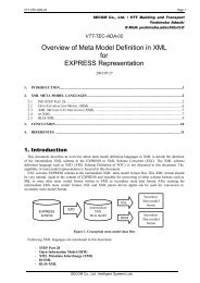
IFC <strong>Model</strong> <strong>View</strong> <strong>Definition</strong> <strong>Format</strong> Page 15 of 25<strong>View</strong> <strong>Definition</strong> work is not starting from scratch there is need for a roadmapfor the work.1. Where are we today? Already implemented IFC <strong>Model</strong> <strong>View</strong> <strong>Definition</strong>sand related implementer’s agreements should be documented usingthe official IFC <strong>Model</strong> <strong>View</strong> <strong>Definition</strong> format.2. How can we make the most out of the existing possibilities? This generationof IFC <strong>Model</strong> <strong>View</strong> <strong>Definition</strong>s should mainly assume existingsoftware and the current IFC <strong>Model</strong> Specification. This combination canalready provide much better value than is available through existingIFC implementations.3. What are the ultimate possibilities of IFC based exchange? This is aforward looking generation of IFC <strong>Model</strong> <strong>View</strong> <strong>Definition</strong>s, which requirechanges to existing software and/or the current IFC <strong>Model</strong> Specification.This stage assumes that software vendors are putting majoreffort into improving their software from the interoperability viewpoint.Typically strong customer demand is a prerequisite for this.This roadmap does not mean a strict sequential approach, i.e. the differentstages can be overlapping. The purpose is to give a general idea how to proceedtowards the target process.2 New exchange requirements arecreated and documented when people/organizations have a common visionfor improving or re-engineering oldprocesses. The need to have formalcontracts about data content drives theformal definition of exchangerequirements.4 If needed, existing IFC <strong>Model</strong> <strong>View</strong><strong>Definition</strong>s are expanded and newdefinitions are created anddocumented to server the needs of thenew/expanded exchange requirements1 Requirements come fromthe deployment – the otherlayers exist to service/enablethe deployment.Process MapExchange RequirementsIFC ImplementationsIFC <strong>Model</strong> <strong>View</strong> <strong>Definition</strong>s3 If needed, customers demandsoftware capable of delivering/consuming the data defined by the newexchange requirements.5 If needed, the IFC<strong>Model</strong> Specification isexpanded to enable thenew/expanded IFC<strong>Model</strong> <strong>View</strong> <strong>Definition</strong>s.IFC <strong>Model</strong> SpecificationFigure 10 Target processCopyright © 2006 International Alliance for Interoperability
IFC <strong>Model</strong> <strong>View</strong> <strong>Definition</strong> <strong>Format</strong> Page 16 of 25IFC <strong>Model</strong> <strong>View</strong> <strong>Definition</strong> formatOverviewIFC Release Independent <strong>Definition</strong>sDocumentsHigh Level DescriptionDiagramsC#3Concept <strong>Definition</strong>sC#2C#1C#4C#1 C#2 C#3C#5IFC Release Binding <strong>Definition</strong>sIFC2x?DocumentsDiagramsHigh Level DescriptionC#5Concept <strong>Definition</strong>sC#2 C#3C#1C#4C#6C#1 C#2 C#3 C#4 C#5C#7Additional documentationFigure 11 <strong>Format</strong> overviewThe format is divided into two main parts; IFC release independent (blue) andIFC release specific (orange). The IFC release independent definitions shouldbe understandable for people without knowledge of IFCs or software implementation.The IFC release specific definitions are targeted towards peoplewriting software code and require some knowledge of IFCs.The IFC release independent part defines the concepts that are used in thedata exchange in generic terms. It may even be used for defining conceptsthat are not exchanged through IFCs. The IFC release specific part is thebinding of the generic concepts into a specific IFC release. It defines how theIFC <strong>Model</strong> Specification is used for exchanging the required data. Each supportedIFC release will naturally have its own binding documentation.Both parts are internally divided into documents and diagrams. Documentsare used for capturing the idea of the view and the concepts used in the view.The same concepts can be reused in different views. The documents providean unconnected collection of concepts. Diagrams are used for defining the relationshipsbetween the concepts in the context of a specific view. The IFCrelease independent diagram may be a configuration of an Exchange Requirementdiagram.Copyright © 2006 International Alliance for Interoperability
IFC <strong>Model</strong> <strong>View</strong> <strong>Definition</strong> <strong>Format</strong> Page 17 of 25ConceptsThe purpose of concepts is to allow a clear definition and reuse of ideas (blue)and software code (orange).Generic ConceptsVariable Concept001WallGroup Concept002Wall PropertiesStatic Concept003Object IDIFC Binding ConceptsVariable Concept001 - IFC2x2WallAdapter Concept002 - IFC2x2Classification AssignmentStatic Concept003 - IFC2x2GUIDVariable concepts have the same name in differentviews, but their content may not be the same.Hence the variable concept must be configuredseparately for each case. This configuration is doneby creating a diagram in which other concepts areconnected to the variable concept.Examples: wall in architectural design to quantitytake-off, wall in structural design to structural analysisGroup concepts provide structure for the genericdiagrams by grouping together static conceptsand/or other group concepts. In some cases thegroup concepts themselves don’t require any otherdefinition than a name.Examples: wall geometry, door propertiesStatic concepts remain the same in all scenarios inwhich they are used. They can be re-used withoutmodification because they don’t contain any options.Examples : Object ID, bounding box geometryThe IFC binding of a variable concept implements ageneric variable concept with the same name.Example: the IFC Binding of the variable concept“Wall” is “Wall”, not “Wall standard case”Adapter concepts are reusable parts of the IFCmodel specification that connect static concepts toa variable concept. There is no correspondencebetween adapter concept and generic group concept.Instead, adapter concepts provide a proposalhow to structure software code in IFC implementationsfor reaching maximal code reuse.Examples: classification assignment, property setassignmentThe IFC binding of a static concept implements oneor more generic static concepts. The names of genericand IFC binding static concepts don’t have tomatch. The documentation of the IFC binding containsa detailed definition how to apply the IFC<strong>Model</strong> Specification.Example: “GUID” implements the generic staticconcept “Object ID”.Copyright © 2006 International Alliance for Interoperability
IFC <strong>Model</strong> <strong>View</strong> <strong>Definition</strong> <strong>Format</strong> Page 18 of 25Each concept has an ID, which uniquely identifies the concept. The name isnot used as the ID because definitions may be translated into different languages.The ID has the following format.-ExamplesTEMP-001ABC-123IAI-057The Author ID “IAI” is assigned only to concepts used in official IFC <strong>Model</strong><strong>View</strong> <strong>Definition</strong>s. When a concept becomes official it gets the Author ID “IAI”and the next available number. The original ID is maintained in the history ofthe concept.When used in a diagram each concept automatically receives a ‘fully qualifiedname’, which identifies it in the context of the diagram. This name is createdby iterating from the concept through all parent concepts to the variable conceptand finally to the IFC <strong>Model</strong> <strong>View</strong> <strong>Definition</strong>. The fully qualified name isused when definitions and configurations are compared with each other.If the example above was from a IFC <strong>Model</strong> <strong>View</strong> <strong>Definition</strong> with the Reference“TEST-01”, the fully qualified name for “Construction Type Name” wouldbe.Test-01:TEMP-003:BLIS-004:BLIS-005:BLIS-006DocumentsThe official format for the documents is PDF. Microsoft Word templates areprovided for creating the documents but any other software or system may beused as well.The documents don’t contain a field for copyright. The document owner is theperson or organization responsible for maintaining a document, i.e. the onlyone allowed to make changes to the document. This is done to prevent asituation in which there are several different, incompatible variations of thesame definition.Copyright © 2006 International Alliance for Interoperability
IFC <strong>Model</strong> <strong>View</strong> <strong>Definition</strong> <strong>Format</strong> Page 19 of 25Figure 12 Template for the high level description of a view 8The purpose of the high level description is to provide a quick overview of theideas of the view. The optimal length for this document is one page.FieldReferenceVersionStatusHistoryDocument OwnerDescriptionDescriptionThe name of the IFC <strong>Model</strong> <strong>View</strong> <strong>Definition</strong>The reference number of the IFC <strong>Model</strong> <strong>View</strong> <strong>Definition</strong>.-The sequential version number of the viewThe status of the view.Sample, Draft, Proposal, Candidate, Official or DeprecatedThe history of the view, e.g. if the view has been created by harmonizingexisting definitions.The person or organization responsible for maintaining the document.Should contain some contact information, e.g. email address.1. What type of data is exchanged between what type of software2. Diagram or picture explaining of the scope of the view3. What is in scope for the view4. What is out of scope for the viewFigure 13 Template for the high level description of the IFC binding of a view 9The purpose of the high level description of an IFC binding of a view is todocument any general decisions that were made in the binding.8 Generic<strong>View</strong>Description.dot9 IfcReleaseSpecific<strong>View</strong>Description.dotCopyright © 2006 International Alliance for Interoperability
IFC <strong>Model</strong> <strong>View</strong> <strong>Definition</strong> <strong>Format</strong> Page 20 of 25FieldReferenceVersionStatusHistoryDocument OwnerDescriptionDescriptionThe IFC release for which the binding is definedThe name of the IFC <strong>Model</strong> <strong>View</strong> <strong>Definition</strong>The reference number of the IFC <strong>Model</strong> <strong>View</strong> <strong>Definition</strong>.-The sequential version number of the viewThe status of the view.Sample, Draft, Proposal, Candidate, Official or DeprecatedAny history specific to the IFC bindingThe person or organization responsible for maintaining the document.Should contain some contact information, e.g. email address.1. Which version of the generic view definition is being used2. Basic principles applied when mapping the generic view to thespecific IFC release, including implementer’s agreements.3. Limitations relative to the generic definitionFigure 14 Template for generic concept definition 10The purpose of the generic concept definition is to document the idea of theconcept independent from any data exchange format.FieldReferenceVersionStatusHistoryDocument OwnerDescriptionDescriptionThe name of the conceptThe reference number of the conceptThe sequential version number of the conceptThe status of the concept.Sample, Draft, Proposal, Candidate, Official or DeprecatedThe history of the concept, e.g. if the concept has beencreated by harmonizing existing definitions.The person or organization responsible for maintaining thedocument. Should contain some contact information, e.g.email address.The “Usage in view definition diagram” defines the place ofthe concept in diagrams. Example:The “<strong>Definition</strong>” provides all necessary information for understandingthe concept. If the definition is longer than onepage it would probably be a good idea to break up the conceptinto several concepts.10 GenericConceptDescription.dotCopyright © 2006 International Alliance for Interoperability
IFC <strong>Model</strong> <strong>View</strong> <strong>Definition</strong> <strong>Format</strong> Page 21 of 25Figure 15 Template for IFC release specific concept definition 11The purpose of the IFC binding definition of a concept is to document how theconcept must be implemented using a specific IFC release.FieldReferenceRelationshipsVersionStatusHistoryDocument OwnerDescriptionDescriptionThe IFC release for which the binding is definedThe name of the conceptThe reference number of the conceptRelationships to other definitions• Implements : the generic concept implemented by the IFCbinding• Extends : the adapter concept a concept is based onThe sequential version number of the conceptThe status of the concept.Sample, Draft, Proposal, Candidate, Official or DeprecatedAny history specific to the IFC bindingThe person or organization responsible for maintaining the document.Should contain some contact information, e.g. email address.The “Usage in view definition diagram” defines the place of theconcept in diagrams. Example:The “instantiation diagram” shows the IFC objects that need to beinstantiated for the concept and any requirements on the attributevalues. Instantiation diagrams may be freely commented and maycontain clarifying drawings. Instantiation diagrams from other conceptsmay be inserted and further specified. Example:11 IfcReleaseSpecificConceptDescription.dotCopyright © 2006 International Alliance for Interoperability
IFC <strong>Model</strong> <strong>View</strong> <strong>Definition</strong> <strong>Format</strong> Page 22 of 25FieldDescriptionThere is no official format for instance diagrams, but the use of thenotation in the example above is encouraged.The “Implementation agreements” are the official agreementsmade regarding the implementation. Most of them will already beshown in the instantiation diagram, but this is the official list used incertification. Example:• The Name attribute of IfcRelAssociatesClassification musthave the value “ConstructionTypeName”. This value is notcase sensitive.• Only subtypes of IfcObject and IfcTypeObject, which are specifiedby the view to have a construction type name, may beused.• The number of IfcClassificationNotationFacet objects is restrictedto one.• The name of the construction type is captured by the Notation-Value attribute of IfcClassificationNotationFacetIn addition the IFC binding definition of a concept may contain any number ofoptional definitions. Such definitions are not part of the official definition, butcan make it easier to understand and implement the definition or help in creatingcertification test cases. Examples:• EXPRESS-G diagram• EXPRESS sub schema• UML diagram• Sample filesDiagramsThe official format for diagrams and configurations is defined by a XMLschema 12 . A Microsoft Visio template 13 is provided but diagrams and configurationsmay be created with any software or system. The Visio template canbe used for reading and writing the official XML format.The XML format for diagrams supports three different styles, which may becombined into the same XML dataset• <strong>Definition</strong>: the concepts used in a diagram and their relationships inthe context of that diagram.• Configuration: The status of the concepts (ON/OFF) and diagramspecific comments for concepts.• Layout: The position, visibility and other layout related settings of conceptsin a diagram. The layout is typically specific to an application, e.g.the MS Visio template uses a ‘Visio layout’. Layouts are not part of theofficial format, only the ability to define layouts.This division makes it possible to create several configurations and layouts forthe same definition.12 <strong>View</strong><strong>Definition</strong>.xsd13 <strong>View</strong> Diagram.vssCopyright © 2006 International Alliance for Interoperability
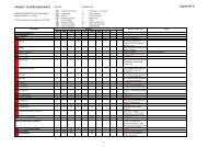
IFC <strong>Model</strong> <strong>View</strong> <strong>Definition</strong> <strong>Format</strong> Page 23 of 25Since the official format for diagrams is an XML representation there is no officialpage size or orientation. Large diagrams have to be kept on one ‘page’,i.e. it is not allowed to split a diagram over several pages. For accommodatinglarge diagrams the Visio template has function for hiding sections of the diagram.Such settings can be saved in a separate layout.A separate <strong>View</strong> Diagram is created for each Variable Concept in the view.Figure 16 Template for generic view diagramFieldDiagram name<strong>View</strong> NameApplication name(optional)Application version(optional)Exchange typeDiagram statusDiagram versionDiagram dateDiagram authorsDocument OwnerDescriptionThe name of the diagram is the name of the variable concept of t hediagram. The name is shown in the title.The name of the IFC <strong>Model</strong> <strong>View</strong> <strong>Definition</strong>The name of the software application for which the diagram is made.The version of the software application for which the diagram ismade.Generic, Import, Export or RoundtripSample, Draft, Proposal, Candidate, Official or DeprecatedThe sequential version number of the diagramThe data the version of the diagram was completedThe authors of the diagramThe person or organization responsible for maintaining the diagram.Should contain some contact information, e.g. email address.Figure 17 Template for IFC release specific view diagramCopyright © 2006 International Alliance for Interoperability
IFC <strong>Model</strong> <strong>View</strong> <strong>Definition</strong> <strong>Format</strong> Page 24 of 25FieldDiagram nameIFC Release<strong>View</strong> NameApplication name(optional)Application version(optional)Exchange typeDiagram statusDiagram versionDiagram dateDiagram authorsDocument OwnerDescriptionThe name of the diagram is the name of the variable concept of the diagram. The name is shown in the title.The IFC release the diagram is defining the binding for. The IFCrelease is shown in the title.The name of the IFC <strong>Model</strong> <strong>View</strong> <strong>Definition</strong>The name of the software application for which the diagram ismade.The version of the software application for which the diagram ismade.Generic, Import, Export or RoundtripSample, Draft, Proposal, Candidate, Official or DeprecatedThe sequential version number of the diagramThe data the version of the diagram was completedThe authors of the diagramThe person or organization responsible for maintaining the diagram.Should contain some contact information, e.g. email address.A diagram defines which concepts are used in a view and the relationshipsbetween those concepts. Static, group and adapter concepts may be placedon either side of the variable concept. There is no predefined meaning for theleft and right side of the variable concept. Connectors in the diagram alwayspoint from left to right. Circular connections between concepts are not allowedand each concept may only be connected to one ‘parent concept’.A concept may be marked ‘mandatory’ if the whole IFC <strong>Model</strong> <strong>View</strong> <strong>Definition</strong>doesn’t work or make sense if that concept is not supported. For examplethermal analysis is not possible if spaces don’t have geometry suitable for thispurpose. Mandatory should be used sparingly, only when absolutely necessary.Software not supporting all mandatory concepts of a view cannot passcertification for that view.In some cases concepts need to be joined together to say “in the context ofthis diagram these concepts go together”. This is done by creating a table inwhich each row represents a set of joined concepts. In a table each row is eitherturned on or off.Copyright © 2006 International Alliance for Interoperability
IFC <strong>Model</strong> <strong>View</strong> <strong>Definition</strong> <strong>Format</strong> Page 25 of 25Diagrams may be configured using two mechanisms; turning concepts off andadding comments to the concepts. In a configuration it is not allowed to deleteconcepts from the diagram. Turning a concept off is used for reducing thescope. If a concept is turned off it means that the concept is irrelevant or notsupported in the context of the diagram. Commenting is used for being morespecific about the scope that remains. In addition diagrams may contain anytext or graphical elements, but such elements are not part of the official definitionand will not be captured in the official XML format.Large diagrams may be placed on one page by hiding concepts. Hiding aconcept does not mean that it is turned off. Hiding is used purely for layoutpurposes.Copyright © 2006 International Alliance for Interoperability