SUSREF - Construction IT research at VTT
SUSREF - Construction IT research at VTT
SUSREF - Construction IT research at VTT

Create successful ePaper yourself
Turn your PDF publications into a flip-book with our unique Google optimized e-Paper software.
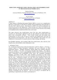
<strong>SUSREF</strong>3 (46)Figure 2.: Contribution of the individual construction element to the environmental impacts of theuse phase according to the zone and building (weighted average). Where Z1, Z2 and Z3,represent European south , central and northern clim<strong>at</strong>ic zones, and “_N” represents the newbuildings. (Source: ImproBuilding Eur 23493 EN_2008)According to the previous figure, old Nordic low rise buildings have the highest energydemands per square meter. Highest losses are across exterior walls, roof and ventil<strong>at</strong>ion.Lowest values are rel<strong>at</strong>ed to southern new high rise buildings, where external area/volumer<strong>at</strong>e and indoor –outdoor temper<strong>at</strong>ure differences are the lowest. In high rise, roof loses don’tcontribute significantly to energy demand, and major loses are rel<strong>at</strong>ed to ventil<strong>at</strong>ion, exteriorwalls, and windows.Therefore, and though <strong>SUSREF</strong> project is aimed <strong>at</strong> improving external walls, for low risebuildings, improving external wall will have not have the expected he<strong>at</strong>ing reduction, if roofand basement remain untouched. For high rise, besides external walls and windows,ventil<strong>at</strong>ion contributes significantly to the energy demand.Improving thermal insul<strong>at</strong>ion in warm and humid regions does not result in the same energysavings as in a moder<strong>at</strong>e clim<strong>at</strong>e. The same holds for the moisture response of theconstruction and indoor air quality. In central Europe, condens<strong>at</strong>ion in winters occurs on theinterior surface of windows, whereas in hot and humid clim<strong>at</strong>es when air conditioning is used,it may occur on the outside part. Therefore, it can be st<strong>at</strong>ed th<strong>at</strong> there is not an uniquesolution for all the clim<strong>at</strong>es.Ventil<strong>at</strong>ion is required to keep indoor air in good conditions and avoid moisture rel<strong>at</strong>edproblems, and therefore a certain number of air changes per hour needs to be guaranteed.The air changes required will depend on the activity and the occupancy level in the dwellingbut conditioning this air to indoor set points it is an energy intensive activity, 0.34Wh areneeded to raise a cubic meter of air by 1ºC. This leads to 1 kWh energy consumption to raise10 ºC outdoor fresh air temper<strong>at</strong>ure for a100 m 2 floorplan dwelling to achieve one air changeper hour. The higher the temper<strong>at</strong>ure difference, floor area or number of air changes, thehigher the energy demand to he<strong>at</strong> this air, and the higher buildings energy consumption willbe <strong>at</strong> the end.Therefore, a low-energy ventil<strong>at</strong>ion system should reconcile two opposite requirements: anadequ<strong>at</strong>e air flow for s<strong>at</strong>isfactory indoor air quality and a minimal air flow to reduce energyconsumption.
<strong>SUSREF</strong>4 (46)This deliverable tackles the issues relevant to achieving a good indoor air quality andminimising buiding energy consumption through different wall refurbishment concepts.2.1.1 Refurbishment practices and energy demand reductionExternal walls represent a large proportion of the he<strong>at</strong> losses for high rise, multirise and forsingle family, and thus represent one of the key parts of those elements of the building withhigher potential to reduce energy consumption. There are several refurbishment practices forwalls, but depending on local circumstances or limit<strong>at</strong>ions (legal, ownership, aesthetics,economics, clim<strong>at</strong>e….) not all of them will be applicable.<strong>SUSREF</strong> has classified wall refurbishment practices in three different groups, depending onthe position of the insul<strong>at</strong>ion as follows and will be referred as:Interior: when interior insul<strong>at</strong>ion is applied.Exterior: when exterior solutions like ETHIC, ventil<strong>at</strong>ed façade are applied.Cavity injection: when insul<strong>at</strong>ion is injected in the pre-existing wall cavity.Other practices:, there refurbishment practices have been classified under thisterm (i.e transparent insul<strong>at</strong>ion, and other new refurbishment practices)The main advantages or disadvantages, with reference to building energy consumption andIndoor Air Quality, have been identified for each of the practices:Table 1.:Exterior RefurbishmentExterior RefurbishmentFor load bearing wall.For hollow brick (exterior and interior) with cavityHollow brick (exterior and interior)with partly insul<strong>at</strong>ed cavity.
<strong>SUSREF</strong>5 (46)Only one sheet wallDouble reinforced concretelayers with insul<strong>at</strong>ionShort description:He<strong>at</strong> losses are reduced or thermal transmittance is reduced by adding outdoorinsul<strong>at</strong>ion. Then a finishing layer is applied, whether acrylic, concrete mortar orceramic pieces in a ventil<strong>at</strong>ed façade.Apply w<strong>at</strong>erproof mortar over existing to avoid moisture filtr<strong>at</strong>ions and thus, humidity.In a load bearing wall, an additional leaf of brickwork could be added to preventmoisture ingressThese options are suitable when external appearance change is not an issue..Advantages: There is no intrusion with the building tenants. Indoor spaces are not affected nor reduced. Thermal bridges are reduced, and therefore energy performance, is improved. Thermal inertia of the existing building elements is not changed. Indoor airtemper<strong>at</strong>ures are smoother compared to solutions with indoor insul<strong>at</strong>ion. It prevents he<strong>at</strong> from sun irradi<strong>at</strong>ion on the outer walls to get into the dwelling.Summer indoor temper<strong>at</strong>ures are smoother. Indoor air rel<strong>at</strong>ive humidity doesn’t suffer major changes.Disadvantages: When aesthetics is an important issue, e.g cultural heritage, these techniquesare not applicable. Special <strong>at</strong>tention should be paid when there is a limit<strong>at</strong>ion to the permittedincrease in external wall thickness in the exterior wall growth, In load bearing walls, strength test should be performed in order to know if wecan increase the load or we have to build another supporting layer. Window frames, balconies have to be studied in detail, otherwise thermalbridges would be enhanced and humidity problems may appear. Building air-tightness is increased and humidity problems may appear if thewall is not sufficient ventil<strong>at</strong>ed.Possible solutions or some issues to be considered: Particular Be care with joints: Avoidful, avoid the joints. Decrease the numberof joints by using with bigger pieces.Replace the finish layer for ceramic tiling with w<strong>at</strong>erproof mortar or in a ventil<strong>at</strong>ed
<strong>SUSREF</strong>6 (46)façade.Note: Not all the solutions developed under <strong>SUSREF</strong> deliverable D4.1”development ofproduct concepts” have been illustr<strong>at</strong>ed. New refurbished layer, have been illustr<strong>at</strong>ed in redcolour.
<strong>SUSREF</strong>7 (46)Table 2.:Insul<strong>at</strong>ion injection in the existing air cavityInsul<strong>at</strong>ion injection in the existing air cavityPerfor<strong>at</strong>ed face brick (exterior)with cavity and interior hollowbrickPerfor<strong>at</strong>ed face brick (exterior)with cavity and interior hollowbrickShort description:When the existing wall has an air cavity, is possible to inject insul<strong>at</strong>ion –polyurethane,EPS-into the cavity by drilling through one of the existing walls.Advantages: Insul<strong>at</strong>ion is increased, and therefore, energy performance of buildings isimproved. Original aesthetic remains.Low intrusion technique. Building tenants don’t have to suffer refurbishmentworks.Disadvantages: Uneven distribution of insul<strong>at</strong>ion in the cavity, th<strong>at</strong> could lead to thermalbridging problem. Increased air tightness. Air gap function is lost When the exterior layer is w<strong>at</strong>er permeable, insul<strong>at</strong>ion may get wet withinsome years, and internal condens<strong>at</strong>ions and mould problems may appear. Slab thermal bridges remain.Insul<strong>at</strong>ion thickness may not be enough to fulfil the new Building EnergyPerformance standards.Possible solutions or some issues to be considered:Avoid insul<strong>at</strong>ion injection in the cavity as far as possible. It would be better to insul<strong>at</strong>eon outer or inner face of the wall because with the injection method the moistureproblem remains.
<strong>SUSREF</strong>8 (46)Table 3.:Interior refurbishment practices:Interior refurbishment practices:Load bearing wallSingle leaf. Only one sheet wallPerfor<strong>at</strong>ed face brick (exterior)with cavity and interior hollowbrickShort description:Apply insul<strong>at</strong>ion layer and over this, put the plasterboard layer. The thickness of theinsul<strong>at</strong>ion can be modified to suit the European clim<strong>at</strong>ic zoneAdvantages: Exterior aesthetics of the building don’t change. For low occupancy buildings, it allows quick response for he<strong>at</strong>ing of the indoorair. When refurbishment <strong>at</strong> building level is not possible Window frame thermal bridges may be reduced if properly performed.Disadvantages:
<strong>SUSREF</strong>9 (46) Thermal inertia of the already existing building elements, except for slabs, willno longer be available. Higher indoor air rel<strong>at</strong>ive humidity for low hygroscopic m<strong>at</strong>erials, especially insummer and southern European countries, th<strong>at</strong> could lead to mould growth. Thermal bridges formed by slab and most of pillars remain. Future drilling of the insul<strong>at</strong>ion may lead to thermal bridges, cool points andmould growth. Air tightness of the dwelling is increased, adequ<strong>at</strong>e air renov<strong>at</strong>ions changeshave to be ensured. Intrusive technique. Tenants have to suffer refurbishment works. Indoor spaces are affected or reduced.As conclusion, there main w<strong>at</strong>ch-points are: In the buildings without w<strong>at</strong>erproof outer m<strong>at</strong>erials there might be moisture and w<strong>at</strong>erinfiltr<strong>at</strong>ion problems Main problem: aesthetics. Always check the load resistance of the existing walls. Preferably choose:-Light or low load exterior co<strong>at</strong>ing.-Ventil<strong>at</strong>ed façade with self-supporting structure. Limited altern<strong>at</strong>ives and solutions.. The contractor person requires:o Short term of execution.o Economic solutions.o Efficient solutions. Interior p<strong>at</strong>ios refurbishment is usually done the same way: insul<strong>at</strong>e outdoor andmortar to finish. Beware of forming a sealed building: without adequ<strong>at</strong>e ventil<strong>at</strong>ion and correct vapourpermeability, refurbishment could cre<strong>at</strong>e moisture problems where these did not existbefore. careful with the tightness of the building it could be self defe<strong>at</strong>ing to makehermetic dwellings. It can appear moistures th<strong>at</strong> we haven’t first. While we do the refurbishment, we could incorpor<strong>at</strong>e renewable energy gener<strong>at</strong>ionactive elements
<strong>SUSREF</strong>10 (46)3. Risks in building refurbishmentBuilding refurbishment may in general solve several kinds of existing problems. Improvedthermal performance of the envelope will generally contribute to indoor comfort, building partsdamaged or disfigured by dampness and mold may be removed or replaced, risk of internalcondens<strong>at</strong>ion may be removed or gre<strong>at</strong>ly reduced, and so on. However some risks are alsopresent. Risks rel<strong>at</strong>ed to indoor clim<strong>at</strong>e and moisture in construction are discussed below.3.1 Indoor clim<strong>at</strong>eHuman thermal comfort is determined by extrinsic factors like air and radiant temper<strong>at</strong>ures,temper<strong>at</strong>ure asymmetry and gradients, rel<strong>at</strong>ive humidity, air movement and clothing, as wellas intrinsic factors like activity, metabolic r<strong>at</strong>e and individual characteristics and preferences.Comfort criteria has often been formul<strong>at</strong>ed on the basis of Ole Fanger’s comfort model asst<strong>at</strong>ed in ISO 7730. In recent years this model has been criticized for being too st<strong>at</strong>ic, and e.g.not allowing for human adapt<strong>at</strong>ion to clim<strong>at</strong>e, see e.g. Moujalled & al 2008. This has led toadaptive models like the one incorpor<strong>at</strong>ed in EN 15251, where a preference for higher indoortemper<strong>at</strong>ure in hot periods is presumed.A complete modelling of all the factors determining thermal comfort requires detailedinform<strong>at</strong>ion on building, furniture, technical equipment (HVAC-systems in particular) and use,as well as extensive CFD 1 -calcul<strong>at</strong>ions. Since many of these factors vary between buildings,and are not to any gre<strong>at</strong> extent affected by wall refurbishment, assessment of indoor clim<strong>at</strong>iceffects of refurbishment options is often restricted to effects on air and radiant temper<strong>at</strong>uresand rel<strong>at</strong>ive humidity. These effects can be assessed by building simul<strong>at</strong>ion or in some casesby simply showing th<strong>at</strong> the proposed refurbishment will improve the conditions in question.However, when refurbishment solutions interact with ventil<strong>at</strong>ion, he<strong>at</strong>ing and / or coolingsystems of the buildings, or moisture conditions are changed in an unfavourable direction,more detailed studies may be called for.3.1.1 Indoor temper<strong>at</strong>ures - summerIn summer situ<strong>at</strong>ions, the most common cause of discomfort is too high internal temper<strong>at</strong>ures.If this is caused by high external temper<strong>at</strong>ures, improving building insul<strong>at</strong>ion will reduce thisproblem. In cases where internal he<strong>at</strong> loads are high and outdoor temper<strong>at</strong>ures are moder<strong>at</strong>e,reduced he<strong>at</strong> flux though the envelope will increase indoor temper<strong>at</strong>ures. The overall effectwill be longer periods with moder<strong>at</strong>ely high temper<strong>at</strong>ures, but lower extremes. Since he<strong>at</strong> isonly removed from the building through the envelope when internal temper<strong>at</strong>ures are higherthan external, the reduced he<strong>at</strong> loss could be compens<strong>at</strong>ed for by increasing the supply ofoutdoor air.Some refurbishment methods, most notable internal insul<strong>at</strong>ion, reduce thermal capacity of thebuilding. The effect of this is higher temper<strong>at</strong>ure fluctu<strong>at</strong>ion, most notably problem<strong>at</strong>ic as hightemper<strong>at</strong>ure peaks when external and / or internal he<strong>at</strong> loads are high. If a refurbishmentoption involves internal insul<strong>at</strong>ion of a structure with high thermal capacity, the overhe<strong>at</strong>ingissue should be given serious consider<strong>at</strong>ion. This implies th<strong>at</strong> simul<strong>at</strong>ions of indoortemper<strong>at</strong>ures should allow for uneven sp<strong>at</strong>ial and temporal distribution of he<strong>at</strong> loads.1 CFD:Comput<strong>at</strong>ional Fluid DynamicsForm<strong>at</strong>ted: Spanish (Intern<strong>at</strong>ionalSort)Form<strong>at</strong>ted: Spanish (Intern<strong>at</strong>ionalSort)Form<strong>at</strong>ted: Spanish (Intern<strong>at</strong>ionalSort)Form<strong>at</strong>ted: Spanish (Intern<strong>at</strong>ionalSort)
<strong>SUSREF</strong>11 (46)Some refurbishment options aim <strong>at</strong> reducing the he<strong>at</strong>ing demand by utilizing solar radi<strong>at</strong>ion.Care should be taken th<strong>at</strong> this does not lead to unwanted he<strong>at</strong>ing in hot periods by e.g.he<strong>at</strong>ing of intake air.3.1.2 Indoor temper<strong>at</strong>ures - winterIn general, winter temper<strong>at</strong>ures will be more comfortable after refurbishments aiming <strong>at</strong>reducing he<strong>at</strong>ing demand, as surface temper<strong>at</strong>ures generally increases, and draughts arereduced. In cases where air infiltr<strong>at</strong>ion through envelop is reduced, and ventil<strong>at</strong>ion relies onexhaust systems, local draughts from intentional or unintentional openings may be moreuncomfortable due to higher air speeds. Install<strong>at</strong>ion of he<strong>at</strong> exchange ventil<strong>at</strong>ion systemswould gre<strong>at</strong>ly reduce or elimin<strong>at</strong>e this problem. .3.1.3 Indoor air rel<strong>at</strong>ive humidity (RH)The indoor RH as such affects thermal comfort directly, but only to a very limited extent exceptin very hot and humid situ<strong>at</strong>ions. It also affects perceived indoor air quality both directly andindirectly. Cool and dry air is generally perceived as favourable, while very low humidity maylead to rapid drying out of mucous membranes and tears film, and may thus be uncomfortable.Very low RH may also contribute to increased amount of airborne dust, while high RH mayincrease the amounts of mite and other allergens.The main determinants for indoor RH are the moisture content of intake air, internal vapourproduction, ventil<strong>at</strong>ion r<strong>at</strong>e, indoor temper<strong>at</strong>ure, and dehumidific<strong>at</strong>ion (including cooling withcondens<strong>at</strong>ion).Moisture diffusion through the building envelop might affect the internal RH, but for acceptableventil<strong>at</strong>ion r<strong>at</strong>es and realistic constructions this effect is very small.The moisture buffering capacity of the building and interior may on the other hand have asubstantial moder<strong>at</strong>ing effect on diurnal and to some extent seasonal moisture fluctu<strong>at</strong>ions. Ifthe refurbishment involves introducing a vapour-tight layer on the inside of a wall with highmoisture storage capacity (e.g. aer<strong>at</strong>ed concrete) the effect on indoor RH may need to beconsidered.3.1.4 Internal condens<strong>at</strong>ion and microbial growth riskCondens<strong>at</strong>ion on internal surfaces occurs when the surface temper<strong>at</strong>ure is lower than thecondens<strong>at</strong>ion temper<strong>at</strong>ure – dew point – of the air adjacent to the surface. In cold clim<strong>at</strong>es,the process typically occurs near thermal bridges in the cold season. Refurbishment th<strong>at</strong>improves thermal insul<strong>at</strong>ion usually allevi<strong>at</strong>es this, but if thermal bridges are not improved,local problems around these may increase.Internal condens<strong>at</strong>ion may also occur in situ<strong>at</strong>ions where hot, humid outdoor air meets coldconstructions of gre<strong>at</strong> thermal capacity. This is well known to cause seasonal problems incrawl spaces, garages and other constructions with little insul<strong>at</strong>ed below-ground walls. Wallrefurbishment would normally reduce the amount of such condens<strong>at</strong>ion, but in cases whereextra thermal mass is cooled by night ventil<strong>at</strong>ion and daytime supply air is very humid, diurnalcycles of condens<strong>at</strong>ion and evapor<strong>at</strong>ion may occur.3.1.5 Interstitial condens<strong>at</strong>ion riskCondens<strong>at</strong>ion may occur inside the building envelop when moisture is transported from a partof the construction with high vapour pressure to a cooler part of the construction. Thistransport may occur by diffusion or convection. Interstitial condens<strong>at</strong>ion most typically occurswhen the outside temper<strong>at</strong>ure is low, but can also happen when the outside air is much hotterthan the inside, and the outside humidity is high. The most familiar example of this is walls ofcold-storage chambers.
<strong>SUSREF</strong>12 (46)Whenever refurbishment involves added insul<strong>at</strong>ion, the temper<strong>at</strong>ure difference over theconstruction increases, and so the condens<strong>at</strong>ion risk also increases. It is important to assesswhether this change of conditions represents an actual risk of condens<strong>at</strong>ion. Risk of interstitialcondens<strong>at</strong>ion is much more dependent on the r<strong>at</strong>io of diffusion resistance between internaland external layers, construction air tightness and ventil<strong>at</strong>ion r<strong>at</strong>es than the actual thermalinsul<strong>at</strong>ion. Thus, constructions with a good airtight vapour barrier retarder or vapour barrierand an external layer open to diffusion are considered robust against interstitial condens<strong>at</strong>ioneven up to very high insul<strong>at</strong>ion levels.3.1.6 External moisture loads and rel<strong>at</strong>ed problemsIn some massive and little insul<strong>at</strong>ed constructions the he<strong>at</strong> transport from the inside to theoutside adds considerably to the drying of the external surface. Internal insul<strong>at</strong>ion of thesewalls may lead to longer wet periods, and moisture-rel<strong>at</strong>ed problems like frost damage orexternal microbial growth may be aggrav<strong>at</strong>ed.4. Assessment of refurbishment practicesThe correct design of refurbishment activities requires of properly addressing the preexistingsitu<strong>at</strong>ion and the potential benefits of the proposed refurbishments. A wholistic approach isrequired, which needs of an exhaustive d<strong>at</strong>a g<strong>at</strong>hering to allow a proper evalu<strong>at</strong>ion.In the following chapters, the needed d<strong>at</strong>a and the output of the evalu<strong>at</strong>ions are shown.4.1 Required d<strong>at</strong>aThe base for the assessment of refurbishment practices is the constructive parameters of thebuilding, which includes several issues ranging from m<strong>at</strong>erial properties to building geometryand glazing r<strong>at</strong>ios. This inform<strong>at</strong>ion is then completed by available HVAC systems and userbehaviour.4.1.1 Building geometry: Geographic loc<strong>at</strong>ion of the building site: local clim<strong>at</strong>e, solar irradi<strong>at</strong>ion, outdoortemper<strong>at</strong>ures, RH and rain will affect in the buildings dynamic energy andhygrothermal behaviour. Local we<strong>at</strong>her files are required to consider building dynamicbehaviour. Building orient<strong>at</strong>ion: building or façades orient<strong>at</strong>ion may affect the incident radi<strong>at</strong>ion oneach of the walls of the building, affecting on solar gains, external walls superficialtempr<strong>at</strong>ures and construction drying process. Floorplan: one of the key parameters th<strong>at</strong> will affect the energy performance of thebuilding is going to be the external surface/volumen r<strong>at</strong>io, this will affect thetransmission losses surface. The lower the r<strong>at</strong>e, the less energy is requiered to keepindoor conditions. Height between slabs: height between slabs will affect basically the floor plan airvolumen r<strong>at</strong>io, and therefore, the air renov<strong>at</strong>ions, and the HVAC needs for airconditioning. It will affect <strong>at</strong> the same time, indoor RH, condtioned for exterior air RHand by moisture production r<strong>at</strong>es. Window size and position. At least the glazing/façade r<strong>at</strong>io. Glazing area and theirorient<strong>at</strong>ion will affect solar gains through them. But <strong>at</strong> the same time, being windowsconstruction elements with weaker U values, these elements would lead to highertransmission losses Loc<strong>at</strong>ion and height of neighbouring buildings: neighbouring buildimgs affect on eachfaçades real available solar radi<strong>at</strong>ion, and therefore, on solar gains, superficialtempear<strong>at</strong>ures and construction rel<strong>at</strong>ive humidity.
<strong>SUSREF</strong>13 (46)4.1.2 Surface constructions <strong>Construction</strong> surfaces definition: Walls, roofs, slabs, internal partitions, basementslabs, glazing,.... for a proper energy and hygrothermal performance of building, it isnecessary to properly define each of the surface th<strong>at</strong> compose the building.Dimensions, height, thickness, lay out. Shading elements, overhangs...etc th<strong>at</strong> willaffect the presence of the shadows, solar radi<strong>at</strong>ion Composing m<strong>at</strong>erials of each surface construction: each construction surface may becomposed of one or more layers of m<strong>at</strong>erials. Depending on m<strong>at</strong>erial properties i.e,thermal conductivity, thermal mass, w<strong>at</strong>er diffusivity, thickness… m<strong>at</strong>erial sheets ofeach construction behaves differently, buffering or transmitting energy and moisture <strong>at</strong>different speeds and thus buildings energy performance and indoors air RH may beaffected by the order layers are built on the constructions. Superficial claddings,vapour barriers and low emissive layers, though extremely thin, may affect a layersbehavior, especially in terms of solar radi<strong>at</strong>ion absorption, w<strong>at</strong>er diffusion and radi<strong>at</strong>iveexchange. Therefore, proper definition of each layer, i.e. m<strong>at</strong>erial, thickness, lay outand position is required in order to analyze the hydrothermal and dynamic energyperformance of a building.4.1.3 M<strong>at</strong>erial propertiesDensity, he<strong>at</strong> conductivity, thermal capacity, w<strong>at</strong>er diffusivity, emissivity… affect the way theenergy and moisture are buffered or transported across the building elements.Depending on the type of m<strong>at</strong>erial opaque or transparent to solar radi<strong>at</strong>ion, the characteristicsor properties required to define them are different. At least the following will be requiredFor opaque m<strong>at</strong>erials (Walls, slabs,…) Thermal conductivity (k or ): is the property of a m<strong>at</strong>erial to conduct he<strong>at</strong> (W/mK).Insul<strong>at</strong>ion m<strong>at</strong>erials have low values 0,026-0,040, concrete values are around 1-2W/mK. It is a moisture dependant value. The higher the moisture, the higher thethermal conductivity of a m<strong>at</strong>erial. Moisture dependent values for widely usedconstruction m<strong>at</strong>erials are known and available in DIN1997. Thickness: layers thickness affect the construction’s total resistence and thermalinertia of the construction. Specific He<strong>at</strong> (Usually not moisture-dependant)., is the capacity of a m<strong>at</strong>erial to storethermal energy. The higher the value, the higher the energy required to increase itstemper<strong>at</strong>ure. Density: with specific he<strong>at</strong> it affects the capacity of a m<strong>at</strong>erial to store energy. Porosity: most of building m<strong>at</strong>erials are porous and can be considered as beingcomprised of a solid m<strong>at</strong>rix and pores filled with air. Moisture will be present in porousm<strong>at</strong>erials in different ways and affects moisture transport in m<strong>at</strong>erials. Rel<strong>at</strong>ive humidity-Moisture content rel<strong>at</strong>iionship curve: the moisture content of am<strong>at</strong>erial is indic<strong>at</strong>ed as the r<strong>at</strong>io of the weight of absorbed moisture to the dry weight ofthe m<strong>at</strong>erial. Moisture content/Rel<strong>at</strong>ive humidity dependant curves for:
<strong>SUSREF</strong>14 (46) Sorption curve gives the equilibrum rel<strong>at</strong>ion between moiture content of the m<strong>at</strong>erialand rel<strong>at</strong>ive humidity of air in contact with or entrapped within the m<strong>at</strong>erial. Suction curve gives the equilibrum between moisture content of the m<strong>at</strong>erial and liquidpressure of pore w<strong>at</strong>er in the m<strong>at</strong>erial W<strong>at</strong>er vapour diffusion resistance factor () ,represents the resistance to moisturetransport or movement through m<strong>at</strong>erial pores in vapour st<strong>at</strong>e, compared to themoisture transpot in air. Mineral rocks are very permeable m<strong>at</strong>erials (1) whilem<strong>at</strong>erials with low open porosity like vapour barriers have very haigh reisstnace factor500.000) Redistribution: liquid transport coefficient. Liquid transport in m<strong>at</strong>erials takes place bycapillary suction, Darcy flow and surface diffusion, being the Darcy’s law being thegoverning mechanism.For fenestr<strong>at</strong>ion m<strong>at</strong>erials (Glazing) Solar he<strong>at</strong> gain factor: represents the total incoming solar energy compared to theincident energy on vertical wall. Thermal conductivity: Visible transmittance: represents the visible wave length energy th<strong>at</strong> finally go throughthe window.For fenestr<strong>at</strong>ion m<strong>at</strong>erials (Frames) Linear thermal transmitance Thickness of the frames4.1.4 Airtightness/Ventil<strong>at</strong>ion Air change r<strong>at</strong>e of each conditioned or unconditioned space. If not constant, schedule.4.1.5 Occupancy Occupancy r<strong>at</strong>e and schedule. Several occupancy r<strong>at</strong>es should be required for mixedusebuildings. Moisture gener<strong>at</strong>ion r<strong>at</strong>e. Nominal power and use schedule of electric equipment, lighting devices, and otherhe<strong>at</strong> sources.4.1.6 HVAC Present he<strong>at</strong>ing system, nominal power, efficiency r<strong>at</strong>e He<strong>at</strong>ing setpoint temper<strong>at</strong>ure and schedule (if not constant) Present cooling system, nominal power, coefficient of performance Cooling setpoint temper<strong>at</strong>ure and schedule (if not constant) Efficiency of he<strong>at</strong> recovery system, if present.
<strong>SUSREF</strong>15 (46) Definition of conditioned/unconditioned areas.4.2 OutputThe assessment procedure will provide inform<strong>at</strong>ion on the hygrothermal performance of thefaçade and the whole building. Depending on the performed approach, some of the d<strong>at</strong>a willnot be available.Building-level results will provide d<strong>at</strong>a on whole-building energy consumptions, Indoor airquality and partial d<strong>at</strong>a on the hygrothermal behaviour of façades. More in-depth façadeevalu<strong>at</strong>ions will provide a full characteriz<strong>at</strong>ion of the hygrothermal performance of façades.Building-level evalu<strong>at</strong>ions will provide the following d<strong>at</strong>a: He<strong>at</strong>ing energy demand Cooling energy demand Ventil<strong>at</strong>ion energy losses Average insul<strong>at</strong>ion properties (RH) and thermal transmittance of façade constructions. Accumul<strong>at</strong>ed damage due to mould growth (EN ISO 13788:2001: RH above 80%), asa control variable for façade performance. Indoor Air quality (EN 15251:2007: RH above both 60% and 70% 2 and below both30% and 25%)The variables are split into three main c<strong>at</strong>egories: Temper<strong>at</strong>ure, w<strong>at</strong>er content and energyneeds. The variables th<strong>at</strong> need to be obtained are listed. Depending on the case, some ofthem will not be necessary or complementary d<strong>at</strong>a should also be collected.D<strong>at</strong>a collection should be collected <strong>at</strong> least in an hourly time series.He<strong>at</strong> transfer r<strong>at</strong>es through the envelope should be monitored in internal surface of thefaçades/roofs…D<strong>at</strong>a provided by both He<strong>at</strong> And Moisture Transfer methods and Conduction TransferFunction methods is similar, excepting th<strong>at</strong> specific of moisture content.4.2.1 Temper<strong>at</strong>ure Exterior Ambient Temper<strong>at</strong>ure [ºC] Ambient Temper<strong>at</strong>ure of conditioned spaces [ºC] Temper<strong>at</strong>ure of unconditioned spaces [ºC] Surface temper<strong>at</strong>ure of external and internal walls, roofs or basement slabs [ºC]4.2.2 W<strong>at</strong>er content Rel<strong>at</strong>ive w<strong>at</strong>er content of the <strong>at</strong>mosphere [RH] Rel<strong>at</strong>ive w<strong>at</strong>er content of conditioned spaces [RH] Rel<strong>at</strong>ive w<strong>at</strong>er content of unconditioned spaces [RH] Surface rel<strong>at</strong>ive w<strong>at</strong>er content of external and internal walls, roofs or basement slabs[RH] Rel<strong>at</strong>ive w<strong>at</strong>er content of insul<strong>at</strong>ion m<strong>at</strong>erials [RH]2 UNE EN ISO 7730
<strong>SUSREF</strong>16 (46)4.2.3 Energy loadsNot only He<strong>at</strong>ing/Cooling loads will be needed but also other he<strong>at</strong> flows will also be quantified: He<strong>at</strong> transfer through walls, roofs, slabs and basement slabs [kW/m2] Sensible internal gains [kWh/m2] L<strong>at</strong>ent internal gains [kWh/m2] He<strong>at</strong> transport through ventil<strong>at</strong>ion [kWh/m2] Solar gains [kWh/m2] He<strong>at</strong>ing/cooling loads [kWh/m2]4.3 Postprocess and d<strong>at</strong>a analysisTwo time bases will be used for d<strong>at</strong>a analysis. Whole year Monthly seriesA detailed analysis of the described phenomena should be made for each.Should he<strong>at</strong> recovery systems be present, the energy loads should be reduced accordingly,as st<strong>at</strong>ed in Deliverable 3.2.The rel<strong>at</strong>ive humidity of insul<strong>at</strong>ion will be monitored and its thermal transmittance calcul<strong>at</strong>edaccordingly as st<strong>at</strong>ed in deliverable 3.2.Interior air quality will be monitored as cumul<strong>at</strong>ive time in non-comfort ranges: interior air RH 70% interior air RH 60%Regarding mould growth, the cumul<strong>at</strong>ive time with wall internal surface RH>80 and surfaceT>0ºC (for Mould growth and corrosion).4.4 Other issues to be considered in simul<strong>at</strong>ionSome issues regarding hygrothermal simul<strong>at</strong>ion of buildings are not rel<strong>at</strong>ed to actual physicalproblems, but to numerical modelling, initializ<strong>at</strong>ion and other issues in simul<strong>at</strong>ion processes.When addressing dynamic moisture transfer in buildings in software such as Energy+ ,numerical convergence can only be reached by short timesteps. These timesteps arerecommended to be shorter than 5 minutes.Also, as moisture transport is a slow process, the initializ<strong>at</strong>ion of simul<strong>at</strong>ions is critical. This issomehow reflected in the need of simul<strong>at</strong>ing 4 years prior to the actual result-providingsimul<strong>at</strong>ion. These 4 years are used as an initializ<strong>at</strong>ion process.
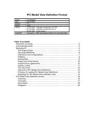
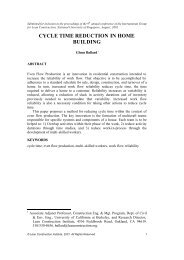
<strong>SUSREF</strong>17 (46)5. Phenomena to be consideredIn order to predict indoor environment and building energy consumption, important he<strong>at</strong> andmass flows must be described. Mass flows concern air as a whole, as well as some of itsspecific constituents, w<strong>at</strong>er vapour being one of them. For several applic<strong>at</strong>ions, w<strong>at</strong>er vapourshould be tre<strong>at</strong>ed separ<strong>at</strong>ely. Indeed, it is the unique component of air th<strong>at</strong> is able tocondense <strong>at</strong> usual conditions, resulting in the release of significant l<strong>at</strong>ent he<strong>at</strong>. The moisturebalance should therefore include both gaseous and liquid forms, e.g. by looking to vapoursources, transport by the air, diffusion and adsorption in solids. W<strong>at</strong>er in its solid form (ice)may also appear in buildings, causing mechanical damages.It should also be st<strong>at</strong>ed th<strong>at</strong> while working <strong>at</strong> a whole building level, we cannot go too deeplyinto the detail of each m<strong>at</strong>erial and component. For example envelope parts are in generalporous media with a complex structure.The following Figure shows an example of a building with just some of the buildingcomponents, loads and transport processes th<strong>at</strong> should be taken into account when analysingwhole-building hygrothermal processes. Most processes occur only locally, but may influencethe adjacent building elements such as rooms or structures. The physical conditions alsoinfluence each other, such as when the temper<strong>at</strong>ure determines the severity of moistureinfluences. To describe a whole building, it is necessary to set up he<strong>at</strong>, air and moisturebalances in various elements of the building, e.g. in individual rooms and constructions, or forfragments of these building elements. It also becomes important to study the interfaces, e.g. toknow how fluxes of he<strong>at</strong>, air and moisture into the building components depend on the localboundary conditions cre<strong>at</strong>ed by the micro clim<strong>at</strong>es of the rooms.Figure 3.: Building with indooe hygrothermal loads (Source: IEA. ECBCS. Annex 41)]
<strong>SUSREF</strong>18 (46)This point gives a general overview of physical phenomena, their interactions and the mainquestions relevant for building modelling.5.1 Energy fluxes.The energy performance of a building can be assessed by analaysing energy balances fromthermodynamics, taking into account the impact of thermal and mechanical energy. Theenergy conserv<strong>at</strong>ion equ<strong>at</strong>ion in a control volume can be written as the flow r<strong>at</strong>e of thermaland mechanical energy th<strong>at</strong> enters the volume minus the flow r<strong>at</strong>e of thermal and mechanicalenergy th<strong>at</strong> leaves the control volumen, plus the r<strong>at</strong>e of energy gener<strong>at</strong>ed in the volume, th<strong>at</strong>must equal the r<strong>at</strong>e of increase in the enerrgy stored in the control volumen.In most building applic<strong>at</strong>ions, kinetic and potential energy contributions can be left out.Vari<strong>at</strong>ion of energy of the control volume is then proportional to temper<strong>at</strong>ure vari<strong>at</strong>ions,density and specific he<strong>at</strong> of the m<strong>at</strong>erial composing the control volume.In buildings, pressure changes are very small compared to the total <strong>at</strong>mospheric pressure.Altern<strong>at</strong>ively the r<strong>at</strong>e of energy storage in the control volume can be assumed equal to internalenthalpy vari<strong>at</strong>ions, proportional to specific he<strong>at</strong> <strong>at</strong> constant pressure for gases.In buildings, the r<strong>at</strong>es of energy entering or leaving the system are he<strong>at</strong> fluxes and energyfluxes due to mass flows. Basically he<strong>at</strong> transfer modes can be distinguished th<strong>at</strong> gener<strong>at</strong>ehe<strong>at</strong> fluxes; they are all due to a temper<strong>at</strong>ure gradient:Enthalpy flows: as some control volumes in buildings are open systems, there is amass flow transporting energy into and out of the system. Mass flow is typically airand/or w<strong>at</strong>er in vapour or liquid st<strong>at</strong>e. Room volume with air flowing in and out is aperfect illustr<strong>at</strong>ion. The mechanical work associ<strong>at</strong>ed with a mass flow is due topressure forces moving the fluid through system boundaries.Convective he<strong>at</strong> flow: Convective he<strong>at</strong> flow refers to he<strong>at</strong> transfer between a solidsurface and a surrounding fluid, or within fluids. The convective he<strong>at</strong> transferprocesses for air are relevant in building applic<strong>at</strong>ions as concerns conditions in theoutdoor environment, he<strong>at</strong> flow in rooms, as well as he<strong>at</strong> flow in cavities in buildingelements or even in pores in building m<strong>at</strong>erials.The convective he<strong>at</strong> transfer coefficient between a solid surface and a fluid hastraditionally been determined empirically, based on some characteristic situ<strong>at</strong>ions, orcalcul<strong>at</strong>ed using detailed modelling of non-isothermal fluid flow. It is highly dependenton air flow conditions whether caused by forced convection or n<strong>at</strong>ural convection. Inn<strong>at</strong>ural convection the driving force is buoyancy induced by vari<strong>at</strong>ions of air density ina volume.For building applic<strong>at</strong>ions it is common to consider th<strong>at</strong> indoor he<strong>at</strong> transfer is mainlydue to n<strong>at</strong>ural convection and therefore is temper<strong>at</strong>ure dependent, and outdoors thehe<strong>at</strong> transfer is mainly due to forced convection and therefore is wind velocitydependent.In many practical applic<strong>at</strong>ions, the convective he<strong>at</strong> transfer coefficient is directly givenas a constant value. For outdoor convection, the dependency on wind speed is morestraightforward because outdoor air velocity is in general given in the we<strong>at</strong>her file. Thepossible difficulty lies in the estim<strong>at</strong>ion of local wind velocities close to the buildingsurfaces.Radi<strong>at</strong>ive he<strong>at</strong> flow: Thermal radi<strong>at</strong>ion he<strong>at</strong> flow involves the exchange ofelectromagnetic waves between surfaces. In building applic<strong>at</strong>ions, two wave-lengthsare of importance:So-called short-wave radi<strong>at</strong>ion, mostly concentr<strong>at</strong>ed in the visible spectrum, comingfrom very hot sources. In normal buildings this terms refers exclusively to solarradi<strong>at</strong>ion and light.
<strong>SUSREF</strong>19 (46)So-called long-wave radi<strong>at</strong>ion, mostly concentr<strong>at</strong>ed in infrared spectra, coming from allsurfaces <strong>at</strong> ambient temper<strong>at</strong>ure.Solar radi<strong>at</strong>ion is mainly short-wave and is composed of direct and diffuse radi<strong>at</strong>ion.Outdoor solar radi<strong>at</strong>ion is given in we<strong>at</strong>her files as boundary conditions. Then takinginto account building geometry, solar shadings and rel<strong>at</strong>ive position of sun, solarirradi<strong>at</strong>ion on each building surface can be computed. Solar transmission throughwindows can also be assessed, using transmittance properties of windows.Infrared radi<strong>at</strong>ion exchange is relevant for both indoor and outdoor surfaces. Radi<strong>at</strong>ivefluxes are proportional to the absolute temper<strong>at</strong>ures raised to the fourth power, andtherefore introduce non-linear terms in the he<strong>at</strong> balance equ<strong>at</strong>ions.Indoor exchanges take place between indoor building surfaces, and outdoorexchanges between outdoor building surfaces and the surroundings. In general,ground and surroundings are assumed to be <strong>at</strong> the outdoor air temper<strong>at</strong>ure.He<strong>at</strong> flow in m<strong>at</strong>erials and structures (conduction): He<strong>at</strong> transfer in solids isdomin<strong>at</strong>ed by conduction, which is energy transport by molecular activity without anybulk motion. For some simple cases analytical solutions can be found. For morecomplex cases numerical comput<strong>at</strong>ions using diverse techniques (such as finitedifferences, control volumes, response factors of finite elements) are helpful. The maindifficulty for building problems comes from the coupling of the generalized he<strong>at</strong>conduction equ<strong>at</strong>ion with mass transfer in porous mediaTo describe a whole building, it is necessary to set up he<strong>at</strong>, air and moisture balances invarious elements of the building –rooms and constructions, or for fragments of those buildingelements. But it also becomes important to study the interfaces, e.g. to know how he<strong>at</strong> fluxes,air and moisture affect in certain points or construction elements where boundary conditionsare different – i.e cracks, thermal bridges, massive construction elements...- from actualbuilding conditions, and may lead to local problems of condens<strong>at</strong>ions, cooler temper<strong>at</strong>ures...Issues to be considered, Thermal bridges: A thermal bridge is cre<strong>at</strong>ed when m<strong>at</strong>erials th<strong>at</strong> are poor thermalinsul<strong>at</strong>ors come into contact, allowing he<strong>at</strong> to flow through the layer. This is usually theweakest point of an envelope and special care is required to prevent he<strong>at</strong>ing escapingfrom the building. Cracks: This is one of the most common problems th<strong>at</strong> can be found in buildingenvelopes. The most general cause of cracking is structural movement of the buildingwith a rigid covering, which is not able to absorb th<strong>at</strong> movement. Rain w<strong>at</strong>er enters thecracks, and when it freezes, its volume increases, making the crack bigger andconsequently the problem gets worse. Massive construction elements. These are elements of high thermal inertia, whichmeans th<strong>at</strong> they work as a storage system and controls the time delay of the he<strong>at</strong>transfer from outside to inside. In winter insul<strong>at</strong>ion is required to avoid losing thebuilding he<strong>at</strong>. On the other hand, in summer a solar protection or something th<strong>at</strong> coolthe element is needed to protect the walls from excessive radi<strong>at</strong>ion.5.2 Air balancesVentil<strong>at</strong>ion plays an essential role as it maintains good indoor air quality by diluting andremoving pollutants, such as human bio effluents, humidity released by occupants and theiractivities and pollutants from m<strong>at</strong>erial and furnishings. Sometimes ventil<strong>at</strong>ion also helps inmeeting cooling needs. A low-energy ventil<strong>at</strong>ion system should reconcile two oppositerequirements: an adequ<strong>at</strong>e air flow for s<strong>at</strong>isfactory indoor air quality and a minimal air flow toreduce energy consumption.A general expression of mass balance applied to a control volume can be written as:
<strong>SUSREF</strong>20 (46)Where:dmdtair m air : is the mass of air [kg] air, in is the density of air [kg/m3].V is the volumetric flow [m3/s]air, inVin air,outVoutAir flows in buildings involve significant transfer of energy and moisture. The airflows are dueto pressure differences driven by wind pressures, buoyancy forces, or some mechanicaldevices, such as fans. Buoyancy forces depend on the vari<strong>at</strong>ions of air density, which istemper<strong>at</strong>ure and moisture content dependent.Air flow in rooms are due to combined effect of buoyancy forces in non-isothermal conditions(n<strong>at</strong>ural convection) and additional pressure differences induced by wind, fans, or stack effect.But, <strong>at</strong> the whole building level the usual approach is to assume a perfectly mixed air zone.The ventil<strong>at</strong>ion may be achieved by n<strong>at</strong>ural ventil<strong>at</strong>ion – through large openings in theenvelope- or through ventil<strong>at</strong>ed systems like HVAC. Mechanical systems: HVAC Air filtr<strong>at</strong>ion through building envelopes Air flow through large openings open doors, window…Mechanical systems:Mechanichal systems are devices where ventil<strong>at</strong>ion is provided by mechanically poweredequipment, such as motor-driven fans and blowers, but not by devices such as wind-driventurbine ventil<strong>at</strong>ors or mechanically oper<strong>at</strong>ed windows.Mechanical systems alllow the possibilty of using energy recovery ventil<strong>at</strong>ion systems th<strong>at</strong>prehe<strong>at</strong> the incoming outdoor air for ventil<strong>at</strong>ion transferring he<strong>at</strong> from the exhaust he<strong>at</strong>ed airto the intake airThese mechanical systems force the air flow inside the building, mainly by injection jets th<strong>at</strong>cre<strong>at</strong>e air streams. The term ’forced’ is used as the flow is not driven by the temper<strong>at</strong>ure ordensity fields.Therefore, inside buildings both forced and n<strong>at</strong>ural convection will occur. Sometimes they willoper<strong>at</strong>e even <strong>at</strong> the same place and time, wh<strong>at</strong> is called mixed convection. Depending on theair flow driving forces, convection coefficients may be affected, and thus,he<strong>at</strong> energy transfercoefficients..Air filtr<strong>at</strong>ion through building envelopes through cracks or large openings:Inter-zonal air flows are in fact flows through the building envelope and interior partitions dueto pressure differences across openings. The openings may be deliber<strong>at</strong>e such as vents orducts, or unintended such as cracks due to construction imperfections. In some particularcases where m<strong>at</strong>erials are very air permeable, the air may flow through the entire wall.Therefore, three types of openings can be distinguished: small openings, large openings, andpossible air flow through porous m<strong>at</strong>erials on the walls.The driving force for th<strong>at</strong> air movement is the pressure difference th<strong>at</strong> can be intentionallyimposed using fans (described above) or may occur due to wind pressure or buoyancy effects.
<strong>SUSREF</strong>21 (46)Air flows through the envelope may have a significant impact on the local hygrothermalconditions within the envelope, especially in cracks, th<strong>at</strong> may lead to local condens<strong>at</strong>ion andmould growth. Indeed local phenomena in the air p<strong>at</strong>h impact on local temper<strong>at</strong>ure andhumidity distribution in the neighbourhood of the opening. Condens<strong>at</strong>ion and mould growthoccur locally and depend on local temper<strong>at</strong>ures but also on local air flows. Therefore very –finely or finely granul<strong>at</strong>ed models like CFD3 in air or 3D fine mesh in envelopes or 2 Denvelopes are required to analyse these particular problems .(Annex 41 ECBCS).5.3 Moisture balancesThe equ<strong>at</strong>ion for conserv<strong>at</strong>ion of mass (m, kg) of w<strong>at</strong>er within a volumen element can bewritten as:dmmoisture Gvapourdiffusion GliquidGconvection Gvapour diffusion GliquidGdt ininin outoutoutm moisture =m liquid w<strong>at</strong>er +m w<strong>at</strong>er vapourconvection msourceWherem is the mass of moisture and is referred to the sum of liquid w<strong>at</strong>er –condensedor adsorbed phase- and the vapour form.G is the moisture flow through the surfaces of the control volume.m is a volumetric moisture production r<strong>at</strong>e.For moisture in porous m<strong>at</strong>erials, the mass of w<strong>at</strong>er vapour in the pores is most likely to benegigible compared to the mass in the adsorbed or condensed phases. The opposite is thecase for cavities in constructions, where the mass of vapour will be gre<strong>at</strong>er than the mass ofcondensed moisture. Nevertheless the mass of humidity in the air of a room is r<strong>at</strong>her smallcompared to the mass of moisture th<strong>at</strong> is stored in building and building’s construction.Moisture in the air: w<strong>at</strong>er in the air is mainly present in vapour st<strong>at</strong>e, though on someoccassions, it may occur in small droplets for example after a hot shower. Te moisture contentof air can be indic<strong>at</strong>ed by the humidity r<strong>at</strong>io (mass of w<strong>at</strong>er per mass of dry air), partial w<strong>at</strong>erpressure, humidity by volume or by dew points.5.3.1 Moisture in m<strong>at</strong>erials:Most building m<strong>at</strong>erials are porous and can be considered as being comprised of a solidm<strong>at</strong>rix and pores filled with air. Moisture will be present in porous m<strong>at</strong>erials as w<strong>at</strong>er vapour inthe air-filled pores, as adsorber layers of e<strong>at</strong>er molecules on the internal pore wall surface, ascapillary condensed liquid w<strong>at</strong>er in the fine pores, as bulk w<strong>at</strong>er in the coarse pores, and asw<strong>at</strong>er which may be physio- chemically bound in the m<strong>at</strong>erial th<strong>at</strong> constitutes the solid m<strong>at</strong>rix.The moisture content of a m<strong>at</strong>erial is indic<strong>at</strong>ed as the r<strong>at</strong>io of the weight of absorbed moistureto the dry weight of the m<strong>at</strong>erial.A certain pressure of w<strong>at</strong>er vapour will exist in the pore air depending on the moisture contentof the m<strong>at</strong>erial. The liquid moisture th<strong>at</strong> may exist in the capillaries of the m<strong>at</strong>erial will exert acertain liquid pressure depending on how much moisture is absorbed in the m<strong>at</strong>erial. Ingeneral, equilibria exist betweeen these pressures and moisture content, and the equilibriaare described by the two types of retetention curves:3 CFD computacional Guild dynamic.
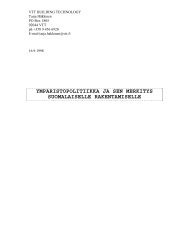
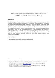
<strong>SUSREF</strong>22 (46) Sorption curve th<strong>at</strong> gives the equilibrum rel<strong>at</strong>ion between moisture content of them<strong>at</strong>erial and rel<strong>at</strong>ive humidity of air in contact with or entrapped within the m<strong>at</strong>erial. Suction curve th<strong>at</strong> gives the equilibrum between moisture content of the m<strong>at</strong>erial andliquid pressure of pore w<strong>at</strong>er in the m<strong>at</strong>erial5.3.2 Moisture transport in m<strong>at</strong>erialsMoisture transport is in general caused by the following processes: Vapour: diffussion Liquid: capillary suction, Darcy Flow and surface diffussion. Convective moisture flow.5.3.2.1 W<strong>at</strong>er vapour diffusionVapour diffusion is a moisture transport mechanism th<strong>at</strong> takes place conditioned by aconcentr<strong>at</strong>ion or partial pressure gradient, and it is governed by Ficks law. It is a rel<strong>at</strong>ivelyslow mechanism compared to other transport forms. However, when liquid and convectivemoisture transport do not take place, vapour diffusion becomes the governing form of moisturetransport and should certainly be considered. This would be the case for air tight m<strong>at</strong>erials inthe hygrocospoic regime and would be the most common transport form for m<strong>at</strong>erials incontact with indoor air.5.3.2.2 Liquid moisture transportLiquid transport redistribution coefficient. Liquid transport in m<strong>at</strong>erials takes place by capillarysuction, Darcy flow and surface diffusion, the Darcy law being the governing mechanism,suction being the driving force for this movement. The w<strong>at</strong>er permeability is a function ofmoisture content. As more pores and larger pores are filled with w<strong>at</strong>er, the liquid moisturetransport will be significantly enhanced.Figure 4.: Moisture permeability in a porous media. W<strong>at</strong>er vapour difussion and liquid moisturetransport (Source: Transferencia de humedad en cerramientos. Iñaki Gomez Arriarán)
<strong>SUSREF</strong>23 (46)5.3.2.3 Convective moisture transportAdvective moisture transport or convective moisture transport occurs when a flow of humid airpasses through a porous m<strong>at</strong>erial or through craks and joints in an assembly. When present,convective moisture should be minimized by preventing undesired air leaks in construction.However convective moisture flow may also, under some we<strong>at</strong>her conditions, be a significantway to dry out excess moisture from constructions, such as by outdoor ventil<strong>at</strong>ed cavities andventil<strong>at</strong>ed <strong>at</strong>tics.5.3.3 Moisture sources and moisture production r<strong>at</strong>e.There are four aspects th<strong>at</strong> limit humidty levels in builidings Human health and comfort: human beings react to global environmental conditions,and comfort conditions can be achieved by different combin<strong>at</strong>ions of variables, beingRH one of the variables th<strong>at</strong> affect human thermal comfort. Present thermal comfortstandards allow RH to vary considerably (ISO 7730), but should meet 30-70% limits toavoid dry skin, eye irrit<strong>at</strong>ion, respir<strong>at</strong>ory problems, microbial growth, and othermoisture rel<strong>at</strong>ed phenomena. Deterior<strong>at</strong>ion of furnishing, high or extremely low RH levels may change size andshape, induce chemical reaction and favour bio-deterior<strong>at</strong>ion of furnishing, so th<strong>at</strong> isimportant to keep indoor air RH <strong>at</strong> certain levels. Safeguarding the building fabric: building fabric may be affected by mould growth,wood deterior<strong>at</strong>ion and corrosion on metal surfaces. The growth of algae on façades isconditioned by the availability of sufficient w<strong>at</strong>er. The form<strong>at</strong>ion of dew <strong>at</strong> night whentemper<strong>at</strong>ures fall below the dewpoint is of special importance, as is the mechanismexplaining algae growth on north facing façades. Minimizing final energy consumption, energy efficiency may conflict with coping withmoisture tolerance, in the sense th<strong>at</strong> avoiding moisture-rel<strong>at</strong>ed problems like mouldcould require extra energy. The task is to identify how to combine effective moisturemanagement with using less energy.Therefore, the knowledge of indoor air humidity and temper<strong>at</strong>ure of buildings is important toavoid all these problems. The main sources of moisture th<strong>at</strong> may affect indoor air are exteriorwe<strong>at</strong>her conditions, moisture th<strong>at</strong> is gener<strong>at</strong>ed by occupants and their activities and moisturereleased by building components or construction m<strong>at</strong>erial the period after construction.5.3.4 External sources th<strong>at</strong> might affect interior indoor conditions:Many sources of excess moisture can lead to high indoor humidity and cause a wide range ofproblems. The main sources of moisture to the indoor air are: The moisture release from the building envelope components to the indoor air: Thisis more important during the initial years of the construction when the constructioncomponents release their initial moisture contents during their first drying process. Moisture th<strong>at</strong> is rel<strong>at</strong>ed to the exterior we<strong>at</strong>her condition: In humid clim<strong>at</strong>e asignificant amount of moisture can be carried into the indoor environment by means ofair leakage through cracks and unintentional openings, or by an intended n<strong>at</strong>ural ormechanical ventil<strong>at</strong>ion system.Wind-driven rain: this phenomenon is rain th<strong>at</strong> is given a horizontal velocitycomponent by the wind. It is one of the most important moisture sources affectingbuilding facades because it penetr<strong>at</strong>es the building envelope enclosure throughdefects and deposit liquid w<strong>at</strong>er inside the construction.
<strong>SUSREF</strong>24 (46) Moisture migr<strong>at</strong>ion from wet soil through walls and floor slabs by capillary force: thisis a major source of moisture to the indoor environment and can cause numerousproblems, such as mould and mildew growth, damp, wet insul<strong>at</strong>ion, musty smell andbacteria growth. To reduce this sort of problem, the flow of moisture from outside hasto be stopped and al leaks must be fixed.5.3.5 Internal sources of moisture:Some indoor moisture production always occurs and can be considered as normal, butwhenever possible, sources of excess indoor moisture should be removed or ventil<strong>at</strong>ed.Occupants: Most moisture produced inside a building is the result of people´srespir<strong>at</strong>ion and perspir<strong>at</strong>ion. The released amount depends on their activities. Whenthere are many occupants in a reduced space, moisture could be a problem.Domestic activities: B<strong>at</strong>hs and showers, cooking, dish washing and laundry increasethe quantity of moisture production.Crawl spaces represent one source of moisture in buildings, so th<strong>at</strong> is important tocover the ground with a vapour barrier. If this is not done high humidity can build up inthe crawl space, contributing to increase humidity inside a building.Air conditioners: Air conditioners cool the air, and raise the rel<strong>at</strong>ive humidity.Occasionally, an air conditioner which is not well design for the space it is cooling canmake the problem worse. An air conditioner of the proper size should be used to avoidthis problem.Plumbing leaks: Sometimes, moisture problems are the result of plumbing leaks.They may be hidden in building cavities such as walls or underne<strong>at</strong>h toilets.The inadequ<strong>at</strong>e use of exhaust fans and the poor ventil<strong>at</strong>ion of high-moisture areas, such askitchens and b<strong>at</strong>hs, cause damage in those areas. If kitchen and b<strong>at</strong>h fans are not installed ornot used, moisture problems commonly arise soon. Adequ<strong>at</strong>e ventil<strong>at</strong>ion should correct thesemoisture problems.6. Assessment toolsThere are different tools or ways to address buildings energy performance, indoor air qualityconditions and construction quality. Depending on the required detail level of the d<strong>at</strong>a, tools <strong>at</strong>building level could be enough but with issues rel<strong>at</strong>ed, for example, with cold bridges, zonesexposed to high humidity, poorly ventil<strong>at</strong>ed areas, corners...- special <strong>at</strong>tention should be paid,and will require more detailed studies th<strong>at</strong> take in account the special boundary conditions th<strong>at</strong>occur near these points.This point has been considered <strong>at</strong> two agreg<strong>at</strong>ion levels, <strong>at</strong> building level and <strong>at</strong> constructionlevel.6.1 At building levelThe methods to calcul<strong>at</strong>e energy performance or indoor air quality <strong>at</strong> building level can beclassified as steady st<strong>at</strong>e methods or dynamic methods.
<strong>SUSREF</strong>25 (46) Quasi-steady-st<strong>at</strong>e methods are those th<strong>at</strong> calcul<strong>at</strong>e the he<strong>at</strong> balance over asufficiently long time (typically one month or a whole season) using daily or monthlymean average temper<strong>at</strong>ures, and which enable to take dynamic effects into account byan empirically determined gain and/or loss utiliz<strong>at</strong>ion factor. Most building intern<strong>at</strong>ionalstandards fall under this c<strong>at</strong>egory. Dynamic methods, are those th<strong>at</strong> calcul<strong>at</strong>e the he<strong>at</strong> balance with short times steps(typically one hour) taking into account the he<strong>at</strong> stored in and released from the massof the building.6.1.1 StandardsStandards rel<strong>at</strong>ed to energy performance set the basis or the methodology to characterize thethermal performance of building and define the required boundary conditions.The main standards th<strong>at</strong> develop thermal energy performances methodologies are the EN 832- Calcul<strong>at</strong>ion of energy use for he<strong>at</strong>ing-residential buildings and ISO 13790: Energyperformance of buildings- calcul<strong>at</strong>ion of energy use for space he<strong>at</strong>ing and cooling.Both of them develop quasy steady st<strong>at</strong>e methods for he<strong>at</strong>ing and cooling energyconsumption estim<strong>at</strong>ion.6.1.1.1 EN 832: Thermal performance of buildings- Calcul<strong>at</strong>ion of energy use forhe<strong>at</strong>ing- residential buildings.This standard provides a simplified calcul<strong>at</strong>ion method for assessment of he<strong>at</strong> use and energyneeded for space he<strong>at</strong>ing of a residential building. It is not developed a specific method forcooling, and doesn’t consider air quality.We would recommend this tool when a rough idea of the whole building he<strong>at</strong>ing energydemand before and after the refurbishment is needed.But monthly he<strong>at</strong>ing demands predicted by this tool may differ substantially from actualdemands, especially in the beginning and end of season: It is not a tool for systemdimensioning. And no issues rel<strong>at</strong>ed to indoor air rel<strong>at</strong>ive humidity are addressed.This standard is based on steady st<strong>at</strong>e energy balance, but takes into account monthly orseasonal external temper<strong>at</strong>ure vari<strong>at</strong>ion, indoor temper<strong>at</strong>ure set point, the dynamic effect ofsolar and internal gains, and transmission and ventil<strong>at</strong>ion losses. It is based on energytransfer, but neither moisture transfer nor l<strong>at</strong>ent he<strong>at</strong> is considered.The standard only applies to residential buildings.The building he<strong>at</strong>ing demand is a rel<strong>at</strong>ionship between he<strong>at</strong> losses –transmission andventil<strong>at</strong>ion- and he<strong>at</strong> gains – internal and solar- and a reduction factor for the he<strong>at</strong> gain, toallow for the dynamic behaviour of the building.The calcul<strong>at</strong>ion method relies in the following equ<strong>at</strong>ions:WhereQ h = Q loss - Q gainsQ h is the building energy need for continuous he<strong>at</strong>ing,Q loss is the total he<strong>at</strong> transfer losses (transmission and ventil<strong>at</strong>ion)Q gains accounts for he<strong>at</strong> gain (internal and solar). H,gn is the dimensionless gain utiliz<strong>at</strong>ion factor.
<strong>SUSREF</strong>26 (46)Where he<strong>at</strong> loss <strong>at</strong> constant internal temper<strong>at</strong>ure it is calcul<strong>at</strong>ed by the following equ<strong>at</strong>ion: (H Hv) ( i e) tQ lossT i = is the internal set-point temper<strong>at</strong>ure e = is the average external temper<strong>at</strong>ure during the calcul<strong>at</strong>ion period:t: is the length of the calcul<strong>at</strong>ion periodH T : is the he<strong>at</strong> loss transmission coefficient, through the envelope elements,calcul<strong>at</strong>ed by the rel<strong>at</strong>ionWhere:H T = AiUi lkk A i is the area of element i of the building envelope, (m 2 )U i is the thermal transmittance of element i of the buildingenvelope, expressed in (W/Km 2 );l k is the length of linear thermal bridge k, (m) k is the linear thermal transmittance of thermal bridge k,expressed in (W/Km)j : is the point thermal transmittance of point thermal bridge j,H V : is the ventil<strong>at</strong>ion loss coefficient. Th<strong>at</strong> is calcul<strong>at</strong>ed byH v = V aCa,where:V is the air flow r<strong>at</strong>e through the builiding; rel<strong>at</strong>ed with air changer<strong>at</strong>e (n) and conditioned space volume (V) , V= nV aC ais the he<strong>at</strong> capacity of the air per volume. 0,34 Wh/m 3 KxjWhere he<strong>at</strong> gains, are calcul<strong>at</strong>ed, summing up the internal gains (Q g ) and solar gains (Q S ).Q g= Q i + Q sInternal gains (Q i ) result form the metabolic gains from occupants, power consumptions ofappliances and lighting devices…)And solar gains resulting from the local sunshine irradi<strong>at</strong>ion (I) and the solar transmission (SHGC of glasses, transparent covering, transparent insul<strong>at</strong>ion….) and absorptioncharacteristics of the collecting areas – i.e., walls behind a transparent covering-..Solar irradi<strong>at</strong>ion is available from meteorological d<strong>at</strong>a, and transmission and absorption areproperties inherent to m<strong>at</strong>erials.Internal gains can be calcul<strong>at</strong>ed from the power of appliances and internal loads.6.1.1.2 ISO 13790: Energy performance of buildings- calcul<strong>at</strong>ion of energy use forspace he<strong>at</strong>ing and coolingCompared to Standard EN 832, ISO 13790 applies to residential and tertiary buildings.
<strong>SUSREF</strong>27 (46)Like EN 832, this standard deploys steady st<strong>at</strong>e energy balance algorithms to estim<strong>at</strong>e spacehe<strong>at</strong>ing demands for buildings, and it uses a mirror image of the approach for he<strong>at</strong>ing forcooling loads.As with EN 832, the monthly calcul<strong>at</strong>ion gives correct results on an annual basis, but theresults for individual months close to the beginning and the end of the he<strong>at</strong>ing and coolingseason can have large rel<strong>at</strong>ive errors.In addtion, ISO 13790 allows more detailed specific<strong>at</strong>ions than EN 832, allowing tointroduction of schedules with different set point, ventil<strong>at</strong>ion r<strong>at</strong>es, internal he<strong>at</strong> gains,moisture gener<strong>at</strong>ionAn altern<strong>at</strong>ive simple method for hourly calcul<strong>at</strong>ions has been added to facilit<strong>at</strong>e thecalcul<strong>at</strong>ion using hourly user schedules (such as temper<strong>at</strong>ure set-points, ventil<strong>at</strong>ion modes,oper<strong>at</strong>ion schedule of movable solar shading and/or hourly control options based on outdooror indoor clim<strong>at</strong>ic conditions). This method produces hourly results, but the results forindividual hours are not valid<strong>at</strong>ed and individual hourly values can have large rel<strong>at</strong>ive errors.6.1.2 Dynamic simul<strong>at</strong>ion tools and methodsDynamic thermo-energetic methods are based on temporal evolution of different points of thebuilding due to dynamic excit<strong>at</strong>ions (i.e we<strong>at</strong>her and building use rel<strong>at</strong>ed). The complexity ofsolving temporal/sp<strong>at</strong>ial equ<strong>at</strong>ions, has led to the development of several simul<strong>at</strong>ion softwareprogrammes (i.e EnergyPlus, TRNSYS, IDA-ICE….)But compared to quasi-steady st<strong>at</strong>e methods, results are generally more precise, allow d<strong>at</strong>aanalysis for shorter period of times, i.e monthly, weekly, daily or on hourly basis and allow theestim<strong>at</strong>ion of peak power demand in order to dimension an HVAC system.Nevertheless, though it seems th<strong>at</strong> the more complex the model is, the better results will be,this is not so simple. Some results from very complex calcul<strong>at</strong>ions, which require very preciseand numerous input d<strong>at</strong>a, and hours or days of project definition and simul<strong>at</strong>ions, canseriously miss the experimental evidence. At the same time, a simplified model programmedin a spreadsheet can give a realistic estim<strong>at</strong>e of the overall behaviour. Therefore, special<strong>at</strong>tention should be paid to defining boundary conditions and the building itself. (for furtherdetail, please refer to ISO 13790)Some of the well known building energy simul<strong>at</strong>ion software, like EnergyPlus and TRNSYSare able to simul<strong>at</strong>e the energy flows in a building in dynamic conditions, and are mainlysitu<strong>at</strong>ed <strong>at</strong> the intermedi<strong>at</strong>e level of “granularity”. All the models also calcul<strong>at</strong>e the moisturelevel in the indoor air and can account for moisture storage in hygroscopic m<strong>at</strong>erial. Thoughw<strong>at</strong>er vapour exchange between room air and surrounding m<strong>at</strong>erial (walls and furniture) isgoverned by three physical processes (transfer of w<strong>at</strong>er vapour between the air and them<strong>at</strong>erial surface, the moisture transfer within the m<strong>at</strong>erial and the moisture storage within them<strong>at</strong>erial), not all the phenomena are always considered in simul<strong>at</strong>ion tools.Nowadays different numerical models are available to describe the transient w<strong>at</strong>er vapourbalance of a room and predict indoor air humidity. A typical room moisture balance includesw<strong>at</strong>er vapour production by moisture sources (humans, plants… ) convective w<strong>at</strong>er vapourtransfer with infiltr<strong>at</strong>ion and ventil<strong>at</strong>ion air, and w<strong>at</strong>er vapour exchange with the building fabricand furniture.6.1.2.1 Energy plus with HAMT and CTF. Energy demand differences
<strong>SUSREF</strong>28 (46)EnergyPlus is a very strong whole building energy model th<strong>at</strong> accounts for energy andmoisture, (moisture sorption by building m<strong>at</strong>erials) and ventil<strong>at</strong>ion which allows n<strong>at</strong>uralventil<strong>at</strong>ion and mechanical system to interact more fully.Depending on the required d<strong>at</strong>a output, i.e energy consumption or energy consumption,indoor air RH, and envelope’s m<strong>at</strong>erial w<strong>at</strong>er content, two main different algorithm may beused:CTF: Conduction Transfer Function –CTF- Conduction transfer functions are anefficient method to compute building energy demand. The zone he<strong>at</strong> gains consist ofspecified internal he<strong>at</strong> gains, air exchange between zones, air exchange with theoutside environment, and convective he<strong>at</strong> transfer from the zone surfaces. However,conduction transfer function series become progressively more unstable. (EnergyPlusEngineering reference).HAMT: The combined he<strong>at</strong> and moisture transfer finite (HAMT) solution algorithm is acompletely coupled, one-dimensional, finite element, he<strong>at</strong> and moisture transfermodel simul<strong>at</strong>ing the movement and storage of he<strong>at</strong> and moisture in surfacessimultaneously from and to both the internal and external environments. It alsosimul<strong>at</strong>es the effects of moisture buffering,HAMT is also be able to provide temper<strong>at</strong>ure and moisture profiles through compositebuilding walls, and help to identify surfaces with high surface humidity.As mentioned before, the level of the input d<strong>at</strong>a required and the comput<strong>at</strong>ional time areincreased considerably from CTF to the HAMT. Because the diffusion of the w<strong>at</strong>er onconstruction m<strong>at</strong>erials is a slow process, it requires more than 5 year simul<strong>at</strong>ion period beforeresults stabilize, which lead to higher comput<strong>at</strong>ional times. Once the system is stabilized, ithas been observed th<strong>at</strong> both he<strong>at</strong>ing and cooling demands calcul<strong>at</strong>ed with HAMT are lowerthan those calcul<strong>at</strong>ed with CTF. In HAMT calcul<strong>at</strong>ions the façade w<strong>at</strong>er content mass is takeninto account, consequently walls have more thermal inertia and worse conductivity, but in anycase, it is expected th<strong>at</strong> thermal inertia prevails, which reduces the calcul<strong>at</strong>ed energyconsumption (for further detail, please refer to <strong>SUSREF</strong>deliverable D3.2 ” Energy and ThermalBehaviour of building types”.)6.1.2.2 IDA-ICEIDA Indoor Clim<strong>at</strong>e and Energy (IDA ICE) is another dynamic tool for the simul<strong>at</strong>ion of energyconsumption, indoor air quality and thermal comfort.IDA ICE covers a large range of phenomena, such as integr<strong>at</strong>ed airflow networks and thermalmodels, CO 2 and moisture calcul<strong>at</strong>ion, vertical temper<strong>at</strong>ure gradients and day lightpredictions. To calcul<strong>at</strong>e moisture transfer in IDA-ICE, the common wall model RCWall shouldbe replaced with HAMWALL. Vapour diffusion through the envelope is considered in moisturetransfer is modeled. The liquid w<strong>at</strong>er transport is not modeled and hysteresis is not taken intoaccount. Many different cases in whole building, he<strong>at</strong> and moisture transport can be simul<strong>at</strong>edwith IDA-ICE, however for comprehensive moisture simul<strong>at</strong>ions the comput<strong>at</strong>ional time isr<strong>at</strong>her high compared to only energy simul<strong>at</strong>ions and the interface is not very “user friendly”.(IEA, Annex 41)This points shows the different results for a case study simul<strong>at</strong>ed EnergyPlus and IDA-ICE.6.1.2.3 Benchmarking of several dynamic simul<strong>at</strong>ion tools for selected casesA benchmarking process has been carried out to assess the differencies obtained when usingdifferent modelling tools such as Energy Plus and IDA ICE for three façade refurbishmentaltern<strong>at</strong>ives. These two software have been applied to case studies in two countries and theirability to handle identical cases assessed.
<strong>SUSREF</strong>29 (46)Simul<strong>at</strong>ions have been performed for refurbishment altern<strong>at</strong>ives and regular local buildingtypes of Spain and Norway presented in deliverable 3.2. Buildings for Spanish and Norwegiancases are similar, but not the same, therefore they have been named as Building 1 andBuilding 2.A total of 6 cases were simul<strong>at</strong>ed with both software, Energy Plus and IDA ICE.Energy Plus, Building 1, Barcelona we<strong>at</strong>her, Solid brick wall, F1.Energy Plus, Building 1, Barcelona we<strong>at</strong>her, Brick cavity wall, F2.Energy Plus, Building 2, Oslo we<strong>at</strong>her, Insul<strong>at</strong>ed wood frame.IDA ICE, Building 1, Barcelona we<strong>at</strong>her, Solid brick wall, F1.IDA ICE, Building 1, Barcelona we<strong>at</strong>her, Brick cavity wall, F2.IDA ICE, Building 2, Oslo we<strong>at</strong>her, Insul<strong>at</strong>ed wood frame.Additionally, an orient<strong>at</strong>ion-dependent study was made to all of the cases, ny rot<strong>at</strong>ing thebuilding 90°.6.1.2.4 Initial d<strong>at</strong>a6.1.2.4.1 Building systems and geometryThe initial d<strong>at</strong>a was defined mainly according to deliverable 3.2. Some differences were foundfrom both Norwegian and Spanish cases and the d<strong>at</strong>a not according to the D3.2 isrepresented in table 5,Table 4.:. Building geometry, initial d<strong>at</strong>a.SpainNorwayWindow area, south 26 % (16,2m²) 35 % (8,4 m²)Window area, westWindow area, north 24 % (15 m²)26 % (16,2 m²) 35 % (8,4 m²)20 % (2,4 m²)Window area, east 24 % (15 m²) 10 % (4,8 m²)The structures were defined according to the deliverable 3.2 and structural <strong>at</strong>tributes used inIDA ICE simul<strong>at</strong>ions are as close to the values used in Energy Plus simul<strong>at</strong>ions as possible.U-values of the constructions used in IDA ICE are presented in the following table. EnergyPlus does not provide the U-values of the constructions, therefore they are not known.Table 5.:Structures used in IDA ICE simul<strong>at</strong>ionsStructure type M<strong>at</strong>erials U-valueW/m²KExt. wall, Structure F1Ext. wall, Structure F2Solid brick façade, noinsul<strong>at</strong>ionBrick cavity wall, noinsul<strong>at</strong>ion0,920,91Ext. wall, Structure 3 Insul<strong>at</strong>ed wood frame 0,42Ext. RoofSpain: WoodNorway: wood with0,090,32Other
<strong>SUSREF</strong>30 (46)insul<strong>at</strong>ionExt. Floor Spain: ConcreteNorway: Concrete withinsul<strong>at</strong>ion2,30,64Int. Wall Gypsum 1,7Window 1 layer2 layersSpain 5,8Norway 2,8SHGC 0,59Table 6.:SystemsSystem Spain NorwayVentil<strong>at</strong>ion N<strong>at</strong>ural ventil<strong>at</strong>ion 0.5 ACH (summer4 ACH)0.35 ACH (summer1.85 ACH)Infiltr<strong>at</strong>ion N<strong>at</strong>ural ventil<strong>at</strong>ion 0 0.15 ACHHe<strong>at</strong>ingCoolingIdeal he<strong>at</strong>erno coolingTable 7.:Internal loads, Spanish casesLoad type Schedule, weekdays Schedule, weekendsOccupancy 3,86 people /building(~2 people /zone)0-8 (100 %), 8-16(25%), 16-24 (50 %)Lighting 4,4 W/m² 0-8 (10 %), 8-18 (30%),18-19 (50%), 19-23(50%), 23-24 (100 %)Equipment 4,4 W/m² 0-8 (10 %), 8-18 (30%),18-19 (50%), 19-23(50%), 23-24 (100 %)24 h (100 %)0-8 (10 %), 8-18 (30%),18-19 (50%), 19-23(50%), 23-24 (100 %)0-8 (10 %), 8-18 (30%),18-19 (50%), 19-23(50%), 23-24 (100 %)Table 8.:Table 1. Internal loads, Norwegian caseLoad type Schedule, weekdays Schedule, weekendsOccupancy 0.033 people / m² 24 h (100%) 24 h (100 %)Lighting 2.9 W/m² 0-7 (0 %), 7-24 (100%) 24 h (100 %)Equipment 4 W/m² 0-7 (0 %), 7-24 (100%) 24 h (100 %)6.1.2.4.2 We<strong>at</strong>herWe<strong>at</strong>her files used in IDA ICE and Energy Plus simul<strong>at</strong>ions were compared to ensure theywere similar. They were nearly identical.The following figure represents the outdoor air temper<strong>at</strong>ure of the we<strong>at</strong>her d<strong>at</strong>a used.
<strong>SUSREF</strong>31 (46)Simul<strong>at</strong>ion we<strong>at</strong>her d<strong>at</strong>a30,025,020,015,0Tout, °C10,05,00,0-5,0-10,01 2 3 3 4 5 6 6 7 8 8 9 10 11 11 12 12-15,0-20,0Time, monthsBarceonaOsloFigure 5.:We<strong>at</strong>her d<strong>at</strong>a used in simul<strong>at</strong>ions6.1.2.5 Results6.1.2.5.1 Presenting of resultsEnergy Plus and IDA ICE have different c<strong>at</strong>egories of presenting the results.Energy Plus: He<strong>at</strong> flux to the building throughenvelope He<strong>at</strong> flux from the building throughenvelope Sensible internal gains L<strong>at</strong>ent internal gains He<strong>at</strong> losses through infiltr<strong>at</strong>ion He<strong>at</strong> gains through infiltr<strong>at</strong>ion He<strong>at</strong> losses through ventil<strong>at</strong>ion He<strong>at</strong> gains through ventil<strong>at</strong>ion Solar gains He<strong>at</strong>ing loadsIDA ICE: Envelope and thermal bridges Internal walls and masses External window and solar Infiltr<strong>at</strong>ion and openings Occupants Equipment Lighting Local he<strong>at</strong>ing unitsIn IDA ICE the gains and losses of different factors are not presented. The result is the energyconsumption where several different factors of each c<strong>at</strong>egory of energy consumption havealready been taken into consider<strong>at</strong>ion. The result is not purely he<strong>at</strong> flux in or out, but e.g.yearly total of he<strong>at</strong> flux in and out through window during the year.
<strong>SUSREF</strong>32 (46)In Energy Plus results are presented separ<strong>at</strong>ely as gains and losses, and it is uncertain wh<strong>at</strong>the different factors of he<strong>at</strong>ing energy consumption consist of. It seems th<strong>at</strong> they describecertain of the he<strong>at</strong> flows in or out of the through the building envelope, and not the yearly totalth<strong>at</strong> would include both, he<strong>at</strong> flux in and out.In IDA ICE he<strong>at</strong> losses through envelope and windows have been separ<strong>at</strong>ed, and in EnergyPlus there is he<strong>at</strong> flux to the building through envelope and he<strong>at</strong> flux from the building throughenvelope. Th “Solar gains” are shown separ<strong>at</strong>ely, and are much bigger th<strong>at</strong> he<strong>at</strong> gainsthrough the envelope. This suggests th<strong>at</strong> the windows are not included in the envelope area.Wh<strong>at</strong> is contradictory is th<strong>at</strong> the “Solar gains” is only a positive value, and it suggests th<strong>at</strong>there are no he<strong>at</strong> losses through windows, or th<strong>at</strong> they are very small in comparison to thegains. This result is similar in all the cases, including the Norwegian case, which suggests th<strong>at</strong>there is something more behind these values than st<strong>at</strong>ed here.6.1.2.5.2 Spanish casesThe energy simul<strong>at</strong>ion results performed with Energy Plus are represented in the followingtables, as they are presented by the simul<strong>at</strong>ion software used in the case simul<strong>at</strong>ion. The lastrow “He<strong>at</strong>ing loads” or “Local he<strong>at</strong>ing units” represents the total he<strong>at</strong>ing demand for thespaces, and they include effects of all the loads, losses and gains.Table 9.:Table 2. Results, Spain, F1, Energy PlusTotal 1 2 3 4 5 6 7 8 9 10 11 12kWh kWh kWh kWh kWh kWh kWh kWh kWh kWh kWh kWh kWhHe<strong>at</strong> flux TO the buildingthrough the envelopeHe<strong>at</strong> flux FROM the buildingthrough the envelope4649 48 81 101 153 195 783 762 993 935 379 158 62-20496 -3560 -3130 -3288 -2587 -1567 -454 -398 -344 -334 -554 -1444 -2835Sensible internal gains 6580 559 505 558 543 558 540 560 558 541 559 540 560L<strong>at</strong>ent internal gains 1189 101 91 99 100 99 97 103 99 98 101 97 103He<strong>at</strong> losses through ventil<strong>at</strong>ion 10256 1072 956 933 733 537 860 812 972 1042 569 727 1045He<strong>at</strong> gains through ventil<strong>at</strong>ion 119 0 0 0 0 2 33 37 31 14 3 0 0Solar gains 19786 963 1286 1630 1710 1971 2074 2221 2195 2020 1724 1085 908He<strong>at</strong>ing loads 15413 3167 2651 2712 1984 1009 4 0 0 0 134 1191 2562Table 10.: Table 3. Results, Spain, F2, Energy PlusMonth Total 1 2 3 4 5 6 7 8 9 10 11 12kWh kWh kWh kWh kWh kWh kWh kWh kWh kWh kWh kWh kWhHe<strong>at</strong> flux TO the buildingthrough the envelopeHe<strong>at</strong> flux FROM the buildingthrough the envelope4723 46 80 101 152 201 802 794 1008 945 380 153 60-20651 -3603 -3152 -3292 -2590 -1552 -460 -401 -346 -335 -562 -1474 -2884Sensible internal gains 6580 559 505 558 543 558 540 560 558 541 559 540 560L<strong>at</strong>ent internal gains 1189 101 91 99 100 99 97 103 99 98 101 97 103He<strong>at</strong> losses through ventil<strong>at</strong>ion 10205 1069 954 930 729 532 859 817 966 1034 556 719 1041He<strong>at</strong> gains through ventil<strong>at</strong>ion 123 0 0 0 0 2 34 38 32 15 3 0 0Solar gains 19786 963 1286 1630 1710 1971 2074 2221 2195 2020 1724 1085 908He<strong>at</strong>ing loads 15522 3199 2667 2716 1987 995 3 0 0 0 139 1217 2599
<strong>SUSREF</strong>33 (46)Table 11.: Results, Spain, F1, IDA ICEMonth Total 1 2 3 4 5 6 7 8 9 10 11 12kWh kWh kWh kWh kWh kWh kWh kWh kWh kWh kWh kWh kWhEnvelope & Thermal bridges -10014 -1508 -1198 -1074 -857 -780 210 -413 -640 -552 -456 -839 -1297Internal Walls and Masses -146 -9 -17 -19 -28 -51 -34 -23 1 11 24 -2 -13External Window & Solar 2295 -1244 -600 -152 409 860 773 1445 854 621 373 -501 -992Infiltr<strong>at</strong>ion & Openings -12423 -1474 -1189 -1112 -886 -699 -605 -1541 -706 -598 -671 -937 -1251Occupants 1976 206 181 194 186 169 122 124 85 124 171 190 202Equipment 2293 195 176 195 188 195 188 195 195 189 195 188 195Lighting 2548 216 196 216 209 217 209 217 217 210 216 209 216Local he<strong>at</strong>ing units 13512 3617 2453 1757 786 96 0 1 0 0 151 1694 2938Table 12.: Results, Spain, F2, IDA ICEMonth Total 1 2 3 4 5 6 7 8 9 10 11 12kWh kWh kWh kWh kWh kWh kWh kWh kWh kWh kWh kWh kWhEnvelope & Thermal bridges -10051 -1508 -1198 -1077 -855 -778 210 -416 -647 -559 -468 -849 -1297Internal Walls and Masses -148 -9 -18 -20 -29 -51 -34 -23 1 11 23 -1 -13External Window & Solar 2313 -1240 -601 -152 409 859 773 1448 858 627 381 -503 -993Infiltr<strong>at</strong>ion & Openings -12417 -1474 -1190 -1111 -886 -701 -605 -1539 -703 -596 -669 -937 -1251Occupants 1976 206 181 194 186 169 122 124 85 124 172 190 202Equipment 2293 195 176 194 188 195 188 195 195 189 195 188 195Lighting 2548 216 196 216 209 217 209 217 217 209 216 209 216Local he<strong>at</strong>ing units 13528 3613 2454 1760 785 96 0 1 0 0 154 1705 2939The following figure presents the yearly vari<strong>at</strong>ion in the he<strong>at</strong>ing energy demand in Spanishsimul<strong>at</strong>ion cases with both Energy Plus and IDA ICE cases.Spain, He<strong>at</strong>ing energy consumption, consturction F1 and F24000350030002500kWh20001500100050001 2 3 4 5 6 7 8 9 10 11 12MonthsF1, IDA F1, EP F2, EP F2, IDAFigure 6.:Results, Spanish case 1, Energy Plus and IDA ICE
<strong>SUSREF</strong>34 (46)The total difference in the yearly he<strong>at</strong>ing energy consumption between Ida and Energy Pluscases is about 13 %. For some reason IDA calcul<strong>at</strong>es slightly lower he<strong>at</strong>ing energyconsumption than Energy Plus. This may be due to different initial d<strong>at</strong>a, or the use of somedefault values which have not been documented. Difference between cases with structures F1and F2 are very small, less than 1 % calcul<strong>at</strong>ed with both IDA ICE and Energy Plus. Most ofthe difference seems to occur during the spring months. In IDA ICE cases the curve is smoothduring the spring months, in Energy Plus cases there can be seen an anomaly wheretemper<strong>at</strong>ure rises for a short period during the spring months. The difference can not beexplained with effects of the out door air temper<strong>at</strong>ure. Only thing th<strong>at</strong> correl<strong>at</strong>es with the timeof year are out door temper<strong>at</strong>ure and solar radi<strong>at</strong>ion. The temper<strong>at</strong>ure is represented in Figure5.: and there seems to be no such difference in the we<strong>at</strong>her d<strong>at</strong>a th<strong>at</strong> would explain thedifference. This could be a result of less solar radi<strong>at</strong>ion entering the building in Energy Pluscases, which may be as a result of the technical d<strong>at</strong>a or the way the simul<strong>at</strong>ion software takesthe solar radi<strong>at</strong>ion into account. Occupancy, lighting and equipment loads use the sameschedule through the year.6.1.2.5.3 Results, Norwegian caseThe following two tables present the results of the Norwegian case, simul<strong>at</strong>ed with bothEnergy Plus and IDA ICE.Table 13.: Results, Norwegian case 3, Energy PlusYht. 1 2 3 4 5 6 7 8 9 10 11 12kWh kWh kWh kWh kWh kWh kWh kWh kWh kWh kWh kWh kWhHe<strong>at</strong> flux TO the building throughthe envelope 1 632 0 5 24 113 311 674 352 306 138 45 5 1He<strong>at</strong> flux FROM the buildingthrough the envelope -4 209 -860 -750 -465 -214 -55 -2 105 -30 -36 -84 -297 -601 -777Sensible internal gains 18 495 1 030 930 1 023 1 007 1 023 3 6331038 1 023 999 1 030 9921038L<strong>at</strong>ent internal gains 3 357 285 258 285 276 285 276 285 285 276 285 276 285He<strong>at</strong> losses through infiltr<strong>at</strong>ion 6 690 895 866 701 557 444 376 237 272 351 544 656 792He<strong>at</strong> gains through infiltr<strong>at</strong>ion 1 0 0 0 0 0 0 0 0 0 0 0 0He<strong>at</strong> losses through ventil<strong>at</strong>ion 15 760 2 089 2 021 1 636 1 299 1 048 891 645 668 818 1 268 1 5301846He<strong>at</strong> gains through ventil<strong>at</strong>ion 4 0 0 0 0 0 0 3 1 1 0 0 0Solar gains 11 740 171 388 800 1 309 2 099 1 9621760 1 450 896 611 197 97He<strong>at</strong>ing loads 27 209 5 440 4 961 3 473 1 795 151 0 0 0 569 2 236 3 8084774Table 14.: Results, Norwegian case 6, IDA ICEYht. 1 2 3 4 5 6 7 8 9 10 11 12kWh kWh kWh kWh kWh kWh kWh kWh kWh kWh kWh kWh kWhEnvelope & Thermal bridges-11659 -1568 -1221 -1194 -889 -770 237 -734 -637 -542 -827 -1147-1417Internal Walls and Masses -46 -5 -6 -10 -16 -78 -34 -30 41 55 -6 -6 -7External Window & Solar 66 -887 -527 -125 274 777 773 736 512 220 -128 -601 -880Infiltr<strong>at</strong>ion & Openings -30553 -4811 -3786 -3822 -2973 -1358 -605 -647 -629 -1360 -2612 -3519-
<strong>SUSREF</strong>35 (46)4348Occupants 2652 260 239 265 259 216 122 105 138 237 275 261 264Equipment 3978 338 306 338 328 338 188 337 338 327 338 327 337Lighting 2885 245 222 245 238 245 209 245 245 237 245 237 245Local he<strong>at</strong>ing units 32776 6433 4779 4310 2791 645 0 0 0 833 2721 4454 5810He<strong>at</strong>ing energy, Norwegian case7 0006 0005 0004 000kWh3 0002 0001 00001 2 3 4 5 6 7 8 9 10 11 12Energy Plus IDA ICEMonthFigure 7.:He<strong>at</strong>ing energy, Norwegian case, Energy Plus and IDA ICEThe difference of the Norwegian cases is about 20 %. The difference has divided quite evenlythrough the whole year and the curves are very much alike. Summer time, while there is nohe<strong>at</strong>ing energy consumption, is in both cases the same length.6.1.2.5.4 Analysis of effects of the orient<strong>at</strong>ionAll cases simul<strong>at</strong>ed with IDA ICE were simul<strong>at</strong>ed in two orient<strong>at</strong>ions, long facades facing northand south (original case) and then turned 90°, long facades facing west and east. The resultsof the comparison are represented inTable 15.: Results, analysis of the effects of the orient<strong>at</strong>ionCase Total Jan Feb March April May June July Aug Sep Oct Nov DecNorway, Insul<strong>at</strong>ed wood frame, 0 ° 28310 5652 4161 3695 2320 519,5 0,4 0 0 674,4 2305 3881 5102Norway, Insul<strong>at</strong>ed wood frame, 90 ° 28581 5669 4191 3750 2384 534,6 0,4 0 0 697,2 2346 3899 5110Spain, Brick cavity wall, 0° 13528 3613 2454 1760 785 96 0 1 0 0 154 1705 2939Spain, Brick cavity wall, 90° 13599 3639 2471 1764 772 92 0 1 0 0 154 1724 2962Spain, Solid brick wall, 0° 13512 3617 2453 1757 786 96 0 1 0 0 151 1694 2938Spain, Solid brick wall, 90° 13585 3642 2471 1765 775 91 0 1 0 0 152 1710 2959The difference in all cases between 0° and 90° is less than 1 %.
<strong>SUSREF</strong>36 (46)6.1.2.6 Conclusions6.1.2.6.1 Yearly vari<strong>at</strong>ionThe biggest difference in the results in all of the cases occurs during the spring time, fromFebruary to April-May. The trend is similar in both Spanish and Norwegian cases, even thoughin all cases some difference can be found during the fall months too. The difference during thespring months is bigger in the Spanish cases. During the summer months (April – August) thehe<strong>at</strong>ing energy consumption is practically non existing in all cases, as it should be.The we<strong>at</strong>her d<strong>at</strong>a is the same in all Spanish cases and in all Norwegian cases. The period ofthe occurrence highlights the differences in calcul<strong>at</strong>ion methods of the windows and solargains and losses. In Energy Plus cases windows were defined in more detail than is possiblein IDA ICE. In IDA ICE it is not possible to see some values, such as the solar he<strong>at</strong> gaincoefficient, th<strong>at</strong> are visible using Energy Plus.It may be thought th<strong>at</strong> the reason for theobserved differences is the solar radi<strong>at</strong>ion processing way of both softwareds . More detailedinform<strong>at</strong>ion of the solar gains and losses would allow for this analysis, but this level ofinform<strong>at</strong>ion has not been available for IDA ICE.6.1.2.6.2 Infiltr<strong>at</strong>ion and ventil<strong>at</strong>ionThe Spanish IDA ICE cases require 21-22 % more he<strong>at</strong>ing energy for ventil<strong>at</strong>ion than theEnergy Plus cases. In Norwegian cases the difference is a little larger, the IDA ICE caserequires about 30 % more he<strong>at</strong>ing energy for ventil<strong>at</strong>ion than the Energy Plus case (combinedventil<strong>at</strong>ion and infiltr<strong>at</strong>ion).Since ventil<strong>at</strong>ion system has no mechanical he<strong>at</strong>er, all makeup air comes as infiltr<strong>at</strong>ionthrough structures, and the schedules of ventil<strong>at</strong>ion and infiltr<strong>at</strong>ion are the same, the effect ofthe ventil<strong>at</strong>ion and infiltr<strong>at</strong>ion should be same in both IDA ICE and Energy Plus calcul<strong>at</strong>ions.The we<strong>at</strong>her files are identical therefore the difference cannot be explained with differenttemper<strong>at</strong>ures of makeup air.One factor affecting the energy demand of ventil<strong>at</strong>ion could be the moisture contents of themakeup air. More detailed analysis of the calcul<strong>at</strong>ion methods could reveal if there are somesignificant differences.6.1.2.6.3 He<strong>at</strong> losses through constructionsThere may be some difference in the way gains and losses through constructions (includingwindows) are calcul<strong>at</strong>ed in Energy Plus and IDA ICE. The way of reporting the results isdifferent, and comparing the factors of the he<strong>at</strong> losses is not therefore easy.The he<strong>at</strong>ing energy demand calcul<strong>at</strong>ed with IDA ICE differs from Energy Plus resultssignificantly in both Spanish and Norwegian cases. In Spanish case IDA ICE result is onlyabout 50 % of the Energy Plus result and in Norwegian case , it is 270% % through thebuilding envelope.This raises many questions about the different definition of structures and effects of suchdetails on he<strong>at</strong>ing energy consumption. In Energy Plus cases the U-values of the structurescould not be verified. The structures were cre<strong>at</strong>ed by m<strong>at</strong>erial layers and the technicalcharacteristics defined for the m<strong>at</strong>erial layers. The final technical values of the constructioncan not be seen from Energy Plus, so e.g. the U-values cannot be compared. In IDA ICE thestructures were made as close to the definitions in Energy Plus cases as possible.For windows, in IDA ICE it is possible to define only U-value, solar he<strong>at</strong> gain coefficient, solartransmittance, visible transmittance and internal and external emissivity. In Energy Plus it ispossible to define glass thickness, solar transmittance, front and back side solar reflectance,visible transmittance, front and back side visible reflectance, infrared transmittance, front andback side infrared emissivity and conductivity.
<strong>SUSREF</strong>37 (46)6.1.2.6.4 Moisture transfer through constructionsWith Energy Plus, the moisture inside the construction can be calcul<strong>at</strong>ed and the software hasmore functions for simul<strong>at</strong>ing the moisture transfer than IDA ICE does. IDA ICE takes theinternal moisture form<strong>at</strong>ion into consider<strong>at</strong>ion when calcul<strong>at</strong>ing the he<strong>at</strong>ing energyconsumption, but the moisture in certain point of the structure can not be simul<strong>at</strong>ed.6.1.2.6.5 Energy Plus / IDA ICEThe comparison of the two software is complic<strong>at</strong>ed by the diversion in the way of presentingthe results. The grouping of the results is very different and effects of different factors are hardto isol<strong>at</strong>e from the results. This may lead to different calcul<strong>at</strong>ion <strong>at</strong>tributes d<strong>at</strong>a in comparisonsimul<strong>at</strong>ions.There are no visual functions, as graphs or 3D or even 2D figures in the software, all the d<strong>at</strong>ais entered into tables. There are no library values and all the needed d<strong>at</strong>a has to be cre<strong>at</strong>edand inserted. Energy Plus is meant to be a simul<strong>at</strong>ion engine for a more visual interface and itis really not meant to be used independently.It is not easy to get a good picture of the initial d<strong>at</strong>a in Energy Plus. All the d<strong>at</strong>a has to bechecked separ<strong>at</strong>ely and in cases the way of presenting the d<strong>at</strong>a is not clear, and e.g. thestructures are presented as coordin<strong>at</strong>es, which makes it hard to see the shape of theconstruction and see if the coordin<strong>at</strong>es have been defined correctly.IDA ICE is much more graphical and more inform<strong>at</strong>ion can be seen <strong>at</strong> a time. In IDA Ice too,there are quite many sheets of different functions of the software and it is quite easy to bypasssome critical inform<strong>at</strong>ion, but yet in IDA ICE there are some default values to be used if thevalue is not specifically defined. In Energy Plus there is no component unless one isspecifically cre<strong>at</strong>ed.Calcul<strong>at</strong>ion methods are not easy to compare and they are not clearly visible from thesoftware interfaces. In IDA ICE it is possible to see the code and some explan<strong>at</strong>ions for wh<strong>at</strong>has been calcul<strong>at</strong>ed in each part of the code, but it is not a manual providing the calcul<strong>at</strong>ionmethods. Also used calcul<strong>at</strong>ion algorithms are not described in the user manuals of thesoftware. Energy Plus does offer more comprehensive manual and it includes inform<strong>at</strong>ionabout the calcul<strong>at</strong>ion methods.Energy Plus offers more functions for simul<strong>at</strong>ions and more flexibility, but it requires a gooduser interface or <strong>at</strong> least very advanced user to compete with other simul<strong>at</strong>ion software. At thesame time IDA ICE is more visual and easy to use, but changes are harder or not possible <strong>at</strong>all to make.7. At construction level7.1.1 Standards7.1.1.1 ISO 13788In general, EN ISO 13788, Annex A (CEN 2001) defines a simple method to assess the riskfor interstitial condens<strong>at</strong>ion within and on a surface of a building envelope construction. Itgives typical temper<strong>at</strong>ure and moisture loads for use in the calcul<strong>at</strong>ion of constructions.These loads are typically given as monthly average values for outdoor air temper<strong>at</strong>ure, e.g. -5 C for January, etc outdoor rel<strong>at</strong>ive humidity, e.g. 90% for January, etc indoor air temper<strong>at</strong>ure, e.g. 20C
<strong>SUSREF</strong>38 (46) indoor air moisture supply, e.g. 4 g/m 3 for T e < 0C and linearly decreasing to 0 g/m 3for T e > 20CThese boundary conditions can be used - and are widely used - for dynamic simul<strong>at</strong>ion of thebuilding constructions but it must be recognised th<strong>at</strong> the standard is intended for steady-st<strong>at</strong>eassessment of interstitial condens<strong>at</strong>ion using the Glaser method.If only thermal 2D/3D calcul<strong>at</strong>ions are performed - e.g. with HEAT2 or Therm - (which arenormally sufficient for studying effects of thermal bridges), a method described in EN ISO13788 for calcul<strong>at</strong>ion of critical temper<strong>at</strong>ures of internal surfaces can be used for assessingthe potential for mould growth.Another standard EN ISO 15026 defines a more realistic present<strong>at</strong>ion of the indoor conditionsthan the EN13788 as the indoor temper<strong>at</strong>ure in EN 15026 flo<strong>at</strong>s up to 25 degrees as afunction of outdoor temper<strong>at</strong>ure during the warm periods and is not fixed <strong>at</strong> 20 as in EN13788,which would require assumption of involving mechanical cooling.7.1.1.2 ISO 10211“ISO 10211: Thermal bridges in building construction - He<strong>at</strong> flows and surface temper<strong>at</strong>ures -Detailed calcul<strong>at</strong>ions” is the base standard for the detailed numerical calcul<strong>at</strong>ion of the linearthermal transmittance of thermal bridges.This standard models a specific building envelope area around the thermal bridge. This isperformed by selecting cut-off planes so th<strong>at</strong> the impact of the thermal bridge is the same as ifthe entire building was to be directly calcul<strong>at</strong>ed.Minimum distances between the cut-off planes and the investig<strong>at</strong>ed thermal bridge are set bythis standard, depending on the detail being studied . The required distances are of about 1m,if no simetry or basement area is involved.Figure 8.: Geometrical model of thermal bridges according to ISO 10211 [Source: ASIEPI P198]Concerning m<strong>at</strong>erial properties, specific criteria are defined for thin layers, and m<strong>at</strong>erialproperty sources. Generally speaking recognized sources should be used, commonly ISO10456 or N<strong>at</strong>ional building product c<strong>at</strong>alogues.For air cavities, thermal resistances should be determined according to different standards(ISO 6946, EN 673 or ISO 10077, depending on the modelled building element).
<strong>SUSREF</strong>39 (46)Two sets of boundary conditions are referred to in ISO 10211: Boundary conditions for he<strong>at</strong> transfer analysis, referred to in ISO 6946. Boundary conditions for condens<strong>at</strong>ion risk assessment, referredo to in ISO 13766.This standard also sets test cases for thermal bridge software valid<strong>at</strong>ion, both for 2- and 3-dimensional analysis.7.1.2 Tools and methodsBuilding physics is about understanding and analysing the he<strong>at</strong>, air and moisture (HAM)interactions - transport and storage - in and around building m<strong>at</strong>erials and constructions. Thiscomplic<strong>at</strong>ed theoretical analysis is typically implemented in more and more advancedsimul<strong>at</strong>ion and modelling tools. The simul<strong>at</strong>ion algorithms solve the coupled he<strong>at</strong>, air andmoisture (=hygrothermal) st<strong>at</strong>es throughout the control volume to be studied as a function oftime and place. Therefore, the dynamic simul<strong>at</strong>ions with hygrothermal simul<strong>at</strong>ion tools are animportant and even necessary part of the assessment work.Some of the most used and verified simul<strong>at</strong>ion tools for hygrothermal analysis of buildingconstructions are WUFI, DELPHIN and M<strong>at</strong>ch. In addition there are quite a few tools for purethermal assessment, mostly two or three-dimensional simul<strong>at</strong>ion tools for assessment of thethermal bridges like HEAT2, VOLTRA and Therm. However, coupled he<strong>at</strong> and moisturetransport need to be analysed in order to assess almost any moisture rel<strong>at</strong>ed performancecriteria.Simul<strong>at</strong>ion tools for building physical analysis <strong>at</strong> construction level can be divided in 2 groups:1. Tools for thermal analysis (H for He<strong>at</strong> or HA for He<strong>at</strong> and Air) and2. Tools for hygrothermal analysis (HAM for He<strong>at</strong>, Air and Moisture or HM for He<strong>at</strong> andMoisture).The first group represents typically numerical models for steady st<strong>at</strong>e or dynamic present<strong>at</strong>ionof the temper<strong>at</strong>ure field in 2 or 3 dimensions. These tools are typically used for analysis andoptim<strong>at</strong>ion of thermal bridges.The models in the second group solve the dynamic and coupled he<strong>at</strong> and moisture transportequ<strong>at</strong>ions. These models are used typically for analysis of the hygrothermal performance ofthe critical parts of a building construction.7.1.2.1 WUFIWUFI is a commercial tool for dynamic hygrothermal analysis of constructions th<strong>at</strong> is widelyused both by the <strong>research</strong>ers and practitioners. It includes most of the basic transportphenomena and it is rel<strong>at</strong>ively easy to use.WUFI, as all the simul<strong>at</strong>ion tools for hygrothermal analysis, considers usually <strong>at</strong> least w<strong>at</strong>ervapour diffusion th<strong>at</strong> is transport of moisture in the air, typically in the pores of a m<strong>at</strong>erial. Thisis the predominant transport mechanism in a very porous m<strong>at</strong>erial (e.g. mineral wool). If thepores of the m<strong>at</strong>erial are very microscopic (e.g. concrete) and/or the m<strong>at</strong>erial is very wet (e.g.wet wood), the capillary conduction will be domin<strong>at</strong>ing. This capillary transport is included inWUFI as well as in other tools like DELPHIN and M<strong>at</strong>ch.Convective moisture transfer takes place in air gaps of a construction and in very open porousm<strong>at</strong>erials like light weight insul<strong>at</strong>ion m<strong>at</strong>erials. The driving force can be the air pressuredifference due to the temper<strong>at</strong>ure gradient within the m<strong>at</strong>erial th<strong>at</strong> enables n<strong>at</strong>ural convection.
<strong>SUSREF</strong>40 (46)Or the convection can be forced by air pressure through any air leakages in the envelope.Hygrothermal convection is normally modelled physically correctly only in the most advanced2D tools, like WUFI 2D.There are 2 different versions of WUFI:WUFI-Pro 4 : A 1D coupled he<strong>at</strong> and moisture calcul<strong>at</strong>ion tool th<strong>at</strong> is the best choice forconstructions and solutions consisting of just homogenous layers. Problems withsimple ventil<strong>at</strong>ed cavities, however, can be studied simplified with this tool to someextendt. WUFI2D: A 2D coupled he<strong>at</strong> and moisture calcul<strong>at</strong>ion tool should be used forconstructions containing inhomogeneous layers, e.g. stone walls, fastenings, andventil<strong>at</strong>ion cavities. 3D effects must be taken into account by qualified modific<strong>at</strong>ion ofthe model, together with a possible 3D thermal calcul<strong>at</strong>ion.<strong>Construction</strong>s with complic<strong>at</strong>ed cavities or elements with active fluids like air or w<strong>at</strong>er/brine orreflective surfaces should be modelled with multi-physics or CFD-tools (Comput<strong>at</strong>ional FluidDynamics tools) (e.g. Comsol 5 , Fluent 6 ) and not with WUFI.Generally, a one-dimensional (1D) HAM-tool like WUFI Pro is sufficient for most of theanalysis with skilled expert use. The comput<strong>at</strong>ion of coupled he<strong>at</strong> and moisture transport intwo dimensions (2D) is usually very time-consuming and the detailed inform<strong>at</strong>ion from a 2D oreven 3D calcul<strong>at</strong>ion may be overruled by other uncertainties. Pure he<strong>at</strong> transmission tools (in2D and 3D) are very usable for optimis<strong>at</strong>ion of the thermal bridges and assessment of thecritical surface temper<strong>at</strong>ures for e.g. mould risk.The simul<strong>at</strong>ion output from WUFI is typically the temper<strong>at</strong>ure and moisture content st<strong>at</strong>esthroughout the defined construction as a function of time. This output can be then postprocessedin order to give input for the assessment.7.1.2.2 KobraKOBRA is a computer program containing an interactive thermal bridge <strong>at</strong>las. This <strong>at</strong>lasprovides the 2-dimensional steady-st<strong>at</strong>e thermal bridge behaviour of specific building details.This program is somewhere betweeen actual thermal bridge <strong>at</strong>lases such as the acreditedconstruction details (UK) and fully free-modelling thermal bridge programs like THERM.Although its DOS interface is outd<strong>at</strong>ed, KOBRA is an interesting tool for building designersdue to its simplicity in use and fast access to results, which moreover are accur<strong>at</strong>e and failsafe.The EUROKOBRA software provides the following results:A section displaying the inside surface resistance Rsi, the inside surface coefficient hi (=1/Rsi)and the boundary temper<strong>at</strong>ures (i and e) used in the condens<strong>at</strong>ion and the he<strong>at</strong> lossevalu<strong>at</strong>ion. As according to most regul<strong>at</strong>ions, different Rsi/hi-values should be used to modeleither a condens<strong>at</strong>ion risk or he<strong>at</strong> loss, the user has to edit the boundary condition and torecalcul<strong>at</strong>e the evalu<strong>at</strong>ion. However, in most cases, the results of the he<strong>at</strong> loss evalu<strong>at</strong>ionobtained using the Rsi/hi-values for condens<strong>at</strong>ion risk evalu<strong>at</strong>ion have a reasonable accuracy.4 http://www.wufi-pro.com/. The simul<strong>at</strong>ion tool is based on the PhD dissert<strong>at</strong>ion: Künzel H.M.:Verfahren zur ein- und zweidimensionalen Berechnung des gekoppelten Wärme- undFeuchtetransports in Bauteilen mit einfachen Kennwerten; Dissert<strong>at</strong>ion Universität Stuttgart 1994.5 http://www.comsol.com/6 http://www.fluent.com/
<strong>SUSREF</strong>41 (46)The condens<strong>at</strong>ion risk evalu<strong>at</strong>ion for up to 3 points on the inside surface of the detail (typicallysymbols K, L, O), the temper<strong>at</strong>ure factor, the surface temper<strong>at</strong>ure and an evalu<strong>at</strong>ion of thecondens<strong>at</strong>ion risk.It should be mentioned th<strong>at</strong> KOBRA only evalu<strong>at</strong>es two-dimensional thermal bridges. Threedimensionalthermal bridges are possibly more sensitive for condens<strong>at</strong>ion risk.The he<strong>at</strong> loss evalu<strong>at</strong>ion: the U-values [W/m2K] of the flanking elements, the total he<strong>at</strong> loss Q[W/m] through the building detail, as well as other he<strong>at</strong> transfer coefficients such as thecoupling coefficient Lie [W/mK], the linear U-values psi-i and psi-e [W/mK] and the mean U-value Um [W/m2K].KOBRA is arranged as a series of building detail collections, each of which contains up to 16details. A report with a thermal bridge analysis is provided for each of these details. Theflexibility of KOBRA lies in the facts th<strong>at</strong> the detail can be edited, by modifying its dimensions,m<strong>at</strong>erials and boundary conditions, autom<strong>at</strong>ically recomputing the temper<strong>at</strong>ure field using anaccur<strong>at</strong>e energy balance technique. Therefore, isotherms and he<strong>at</strong> flow lines can berepresented in a clear way.The EUROKOBRA d<strong>at</strong>abase contains 9 sections: massive walls without insul<strong>at</strong>ion massive walls with outside insul<strong>at</strong>ion massive walls with inside insul<strong>at</strong>ion partially insul<strong>at</strong>ed cavity walls fully insul<strong>at</strong>ed cavity walls light wooden constructions window frame sections simplified details according to PrEN/ISO 14683 (July 1996) didactic examplesThe first six sections, the other being particular cases, contain about 40 to 50 <strong>at</strong>las pages ofwhich the names refer to the type of the building details in it. The following types may occur: Wall, horizontal section, no window Concrete column in wall section Window connection in horizontal wall section Found<strong>at</strong>ion Floor-slab to wall connections Overhangs Fl<strong>at</strong> roof sections Pitched roof sectionsterrace including window connections Balconyes includingwindow connections
<strong>SUSREF</strong>42 (46)7.1.2.3 ThermTHERM is a st<strong>at</strong>e-of-the-art, Microsoft Windows-based computer program developed <strong>at</strong>Lawrence Berkeley N<strong>at</strong>ional Labor<strong>at</strong>ory (LBNL) THERM is a two-dimensional he<strong>at</strong>-transfermodelling software focused in building components such as windows, walls, found<strong>at</strong>ions,roofs, and doors; appliances; and other products where thermal bridges are of concern. He<strong>at</strong>transferin THERM is based on the finite-element method, which can model complic<strong>at</strong>edgeometries in building products. He<strong>at</strong>-transfer analysis in therm provides a product’s he<strong>at</strong>transfer coefficient and its local temper<strong>at</strong>ure p<strong>at</strong>terns, which are rel<strong>at</strong>d to problems such ascondens<strong>at</strong>ion, moisture damage, and structural integrity.THERM is part of a wider software package called WINDOW, which is focused on he<strong>at</strong> andradi<strong>at</strong>ion transfer through windows and glazed areas, also under continous development byLBNL. THERM's results can be used with WINDOW's center-of-glass optical and thermalmodels to determine total window product U-factors and Solar He<strong>at</strong> Gain Coefficients.Figure 9.: Temper<strong>at</strong>ure distribution in a Curtain Wall [Source: TECNALIA]THERM has three basic components:Graphic User Interface: A graphic user interface th<strong>at</strong> allows the drawing of crosssections of the product or component evalu<strong>at</strong>ed.He<strong>at</strong> Transfer Analysis: A he<strong>at</strong>-transfer analysis component th<strong>at</strong> includes: anautom<strong>at</strong>ic mesh gener<strong>at</strong>or to cre<strong>at</strong>e the elements for the finite-element analysis, a finiteelementsolver, an optional error estim<strong>at</strong>or and adaptive mesh gener<strong>at</strong>or, and an optionalview-factor radi<strong>at</strong>ion model.Results: A results displayer.THERM has standard graphic capabilities associ<strong>at</strong>ed with the Microsoft Windows oper<strong>at</strong>ingsystem. THERM has powerful drawing capabilities th<strong>at</strong> make it easy to model the geometry ofthe cross section of a building component. Direct geometry drawing as well as DXF or bitmapimparting capabilities are availabe.
<strong>SUSREF</strong>43 (46)The following thermal properties must be defined for the cross section geometry:M<strong>at</strong>erial properties (broken into two classes: solids and cavities) of eachcomponent of the cross section,Boundary conditions <strong>at</strong> the external edges of the cross section.THERM uses two-dimensional (2D) conduction and radi<strong>at</strong>ion he<strong>at</strong>-transfer analysis based onthe finite-element method, which can model the complic<strong>at</strong>ed geometries of fenestr<strong>at</strong>ionproducts and other building elements. This method requires th<strong>at</strong> the cross section be dividedinto a mesh made up of non-overlapping elements. This process is performed autom<strong>at</strong>ically byTHERM using the Finite Quadtree method. Once you have defined the cross section’sgeometry, m<strong>at</strong>erial properties, and boundary conditions, THERM meshes the cross section,performs the he<strong>at</strong>-transfer analysis, runs an error estim<strong>at</strong>ion, refines the mesh if necessary,and returns the converged solution.The results from THERM’s finite-element analysis provides the following d<strong>at</strong>a:U-factors,isotherms,color-flooded isotherms,he<strong>at</strong>-flux vector plots,color-flooded lines of constant flux,temper<strong>at</strong>ures (local and average, maximum and minimum).