CT/-RSOC or CT/-BSOC - BAPI
CT/-RSOC or CT/-BSOC - BAPI
CT/-RSOC or CT/-BSOC - BAPI
- No tags were found...

You also want an ePaper? Increase the reach of your titles
YUMPU automatically turns print PDFs into web optimized ePapers that Google loves.
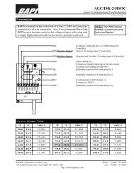
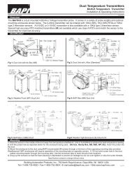
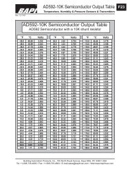
*<strong>CT</strong>/-<strong>RSOC</strong> <strong>or</strong> <strong>CT</strong>/-BSO<strong>CT</strong>ermination and Troubleshooting16475_ins_circon_rsocProduct Indentificationrev. 12/16/05Fig. 1: Delta EnclosureMountingFig. 2: Delta Enclosurewith Bi-Metal DisplayFig. 3<strong>BAPI</strong>-Stat 2 EnclosureFig. 4Delta EnclosureFig. 5<strong>BAPI</strong>-Stat 2EnclosureMounting hardware isprovided f<strong>or</strong> bothjunction box anddrywall installation(junction box installationshown).Junction Box1. Pull the wire through the wall and out of the junction box, leaving about six inches free.2. Pull the wire through the hole in the base plate.3. Secure the base to the box using the #6-32 x 1/2 inch mounting screw provided.4. Terminate the unit acc<strong>or</strong>ding to the guidelines in Termination on page 2.5. Attach Cover by latching it to the top of the base, rotating the cover down and snapping it into place.6. Secure the cover by backing out the lock-down screws using a 1/16" allen wrench until they are flush with the bottom ofthe cover.Drywall Mounting1. Place the base plate against the wall where you want to mount the sens<strong>or</strong>.2. Using a pencil, mark out the two mounting holes and the area where the wires will come through the wall.3. Drill two 3/16" holes in the center of each marked mounting hole. Insert a drywall anch<strong>or</strong> into each hole.Drywall Mounting continued on next page...*Some items may not be CE compliant, call Circon f<strong>or</strong> additional inf<strong>or</strong>mation.Specifications subject to change without notice.CIRCON SYSTEMS CORPORATION • 110 - 6651 Fraserwood Place, Richmond, BC, Canada VJW 1J3 • website www.circon.comtoll free 1.800.338.1866 • telephone 604.232.4700 • technical supp<strong>or</strong>t 1.877.350.2299 • facsimile 604.232.47471
<strong>CT</strong>/-<strong>RSOC</strong> <strong>or</strong> <strong>CT</strong>/-BSO<strong>CT</strong>ermination and Troubleshooting16475_ins_circon_rsocrev. 12/16/05Setpoint Range1K RTD Sens<strong>or</strong>: Setpoint Range: 909Ω to 1309Ω Example: [<strong>CT</strong>/1K-<strong>RSOC</strong>]10K-3 Thermist<strong>or</strong>: Setpoint Range: 6.19KΩ to 26.19KΩ Example: [<strong>CT</strong>/10K-3-<strong>RSOC</strong>]Jumper “J11” SettingsDifferential GroundCommon GroundCommunication WiringNote: Male Jack shown f<strong>or</strong> clarityFig. 7C45 Comm.JackFig. 7C35 Comm. JackC35 Communications WiringBoard Terminal C35 ConnectionNET-AGroundNET-BTipC45 Communications WiringBoard Terminal C45 ConnectionNET-A Terminal 1NET-B Terminal 2Optional Bi-Metal DisplaysCelsius Display(Can not be used with C45 Comm. Jack)Fahrenheit Display10 15 20 25 3050 60 70 80 90Specifications subject to change without notice.CIRCON SYSTEMS CORPORATION • 110 - 6651 Fraserwood Place, Richmond, BC, Canada VJW 1J3 • website www.circon.comtoll free 1.800.338.1866 • telephone 604.232.4700 • technical supp<strong>or</strong>t 1.877.350.2299 • facsimile 604.232.47473
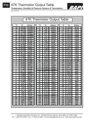
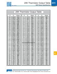
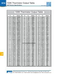
<strong>CT</strong>/-<strong>RSOC</strong> <strong>or</strong> <strong>CT</strong>/-BSO<strong>CT</strong>ermination and Troubleshooting16475_ins_circon_rsocTroubleshootingPossible Problems:General troubleshootingrev. 12/16/05Possible Solutions:- Determine that the input is set up c<strong>or</strong>rectly in the controller’s and building automationsoftware.- Check wiring f<strong>or</strong> proper termination- Check f<strong>or</strong> c<strong>or</strong>rosion at either the controller <strong>or</strong> the sens<strong>or</strong>. Clean off the c<strong>or</strong>rosion, re-stripthe interconnecting wire and reapply the connection. In extreme cases, replace thecontroller, interconnecting wire and/<strong>or</strong> sens<strong>or</strong>.- Label the terminals that the interconnecting wires are connected to at the sens<strong>or</strong> end andthe controller end. Disconnect the interconnecting wires from the controller and thesens<strong>or</strong>. With the interconnecting wires separated at both ends measure the resistancefrom wire-to-wire with a multimeter. The meter should read greater than 10 Meg-ohms,open <strong>or</strong> OL depending on the meter you have. Sh<strong>or</strong>t the interconnecting wires together atone end. Go to the other end and measure the resistance from wire-to-wire with a multimeter.The meter should read less than 10 ohms (22 gauge <strong>or</strong> larger, 250 feet <strong>or</strong> less). Ifeither test fails, replace the wire.- Don’t f<strong>or</strong>get to reconnect the wires.Temperature reading isinc<strong>or</strong>rectSetpoint reading is inc<strong>or</strong>rectOverride is not w<strong>or</strong>kingc<strong>or</strong>rectly- Determine that the temperature sens<strong>or</strong>s wires are connected to the c<strong>or</strong>rect controller inputterminals and are not loose.- Check the wires at the sens<strong>or</strong> f<strong>or</strong> proper connections.- Measure the physical temperature at the temperature sens<strong>or</strong>’s location using an accuratetemperature standard. Disconnect the temperature sens<strong>or</strong> wires and measure the temperaturesens<strong>or</strong>’s resistance across the sens<strong>or</strong> output pins with an ohmmeter. Comparethe temperature sens<strong>or</strong>’s resistance to the appropriate temperature sens<strong>or</strong> table below. Ifthe measured resistance is different from the temperature table by m<strong>or</strong>e than 5% callCircon technical supp<strong>or</strong>t. Don’t f<strong>or</strong>get to reconnect the wires.- Make sure the sens<strong>or</strong> leads are not touching one another <strong>or</strong> any other circuit components.- Make sure that the setpoint output is c<strong>or</strong>rect. Remove the setpoint output wire and checkthe output f<strong>or</strong> the c<strong>or</strong>rect resistance output. See the setpoint range section of thisdocument f<strong>or</strong> details. Don’t f<strong>or</strong>get to reconnect the wire.-Check that the resistance across the temperature sens<strong>or</strong> output is less than 5 ohms whenthe override switch is pushedThermist<strong>or</strong> Output Table°F ° C 1K10K-3°F ° C 1K10K-31,000 ohms@32°F (0°C)10,000 ohms @77°F (25°C)1,000 ohms@32°F (0°C)10,000 ohms @77°F (25°C)50.010.0 103918,78677.0 25.0 109710,00055.012.8 105016,64978.0 25.6 10999,77860.015.6 106114,78380.0 26.7 11049,35362.016.7 106514,10382.0 27.8 11088,94864.017.8 106913,45984.0 28.9 11128,56266.018.9 107412,84786.0 30.0 11178,19668.020.0 107812,26888.0 31.1 11217,84770.021.1 108211,71790.0 32.2 11257,51672.022.2 108711,19595.0 35.0 11356,75474.023.3 109110,698100.0 37.8 11456,07976.024.4 109510,226104.0 40.0 1155.4 5,5944