Temperature Accuracy of Thermistors and RTDs - BAPI
Temperature Accuracy of Thermistors and RTDs - BAPI
Temperature Accuracy of Thermistors and RTDs - BAPI

Create successful ePaper yourself
Turn your PDF publications into a flip-book with our unique Google optimized e-Paper software.
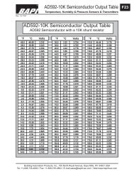
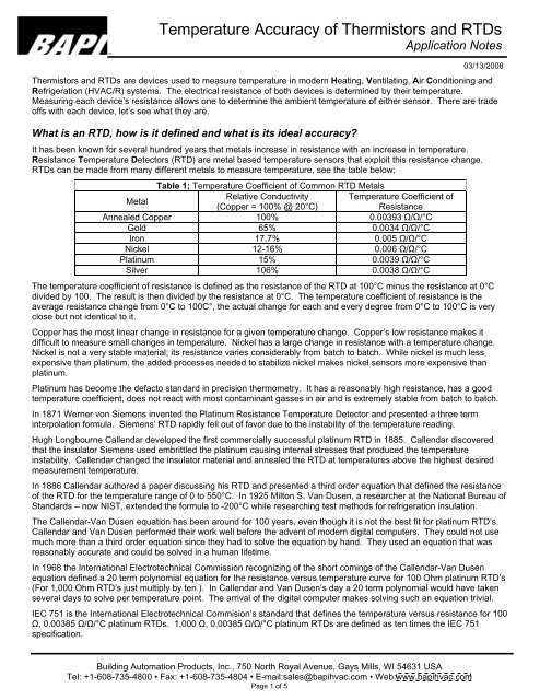
<strong>Temperature</strong> <strong>Accuracy</strong> <strong>of</strong> <strong>Thermistors</strong> <strong>and</strong> <strong>RTDs</strong>Application Notes03/13/2008<strong>Thermistors</strong> <strong>and</strong> <strong>RTDs</strong> are devices used to measure temperature in modern Heating, Ventilating, Air Conditioning <strong>and</strong>Refrigeration (HVAC/R) systems. The electrical resistance <strong>of</strong> both devices is determined by their temperature.Measuring each device s resistance allows one to determine the ambient temperature <strong>of</strong> either sensor. There are trade<strong>of</strong>fs with each device, let s see what they are.What is an RTD, how is it defined <strong>and</strong> what is its ideal accuracy?It has been known for several hundred years that metals increase in resistance with an increase in temperature.Resistance <strong>Temperature</strong> Detectors (RTD) are metal based temperature sensors that exploit this resistance change.<strong>RTDs</strong> can be made from many different metals to measure temperature, see the table below;Table 1; <strong>Temperature</strong> Coefficient <strong>of</strong> Common RTD MetalsMetalRelative Conductivity <strong>Temperature</strong> Coefficient <strong>of</strong>(Copper = 100% @ 20°C)ResistanceAnnealed Copper 100% 0.00393 / /°CGold 65% 0.0034 / /°CIron 17.7% 0.005 / /°CNickel 12-16% 0.006 / /°CPlatinum 15% 0.0039 / /°CSilver 106% 0.0038 / /°CThe temperature coefficient <strong>of</strong> resistance is defined as the resistance <strong>of</strong> the RTD at 100°C minus the resistance at 0°Cdivided by 100. The result is then divided by the resistance at 0°C. The temperature coefficient <strong>of</strong> resistance is theaverage resistance change from 0°C to 100C°, the actual change for each <strong>and</strong> every degree from 0°C to 100°C is veryclose but not identical to it.Copper has the most linear change in resistance for a given temperature change. Copper s low resistance makes itdifficult to measure small changes in temperature. Nickel has a large change in resistance with a temperature change.Nickel is not a very stable material; its resistance varies considerably from batch to batch. While nickel is much lessexpensive than platinum, the added processes needed to stabilize nickel makes nickel sensors more expensive thanplatinum.Platinum has become the defacto st<strong>and</strong>ard in precision thermometry. It has a reasonably high resistance, has a goodtemperature coefficient, does not react with most contaminant gasses in air <strong>and</strong> is extremely stable from batch to batch.In 1871 Werner von Siemens invented the Platinum Resistance <strong>Temperature</strong> Detector <strong>and</strong> presented a three terminterpolation formula. Siemens RTD rapidly fell out <strong>of</strong> favor due to the instability <strong>of</strong> the temperature reading.Hugh Longbourne Callendar developed the first commercially successful platinum RTD in 1885. Callendar discoveredthat the insulator Siemens used embrittled the platinum causing internal stresses that produced the temperatureinstability. Callendar changed the insulator material <strong>and</strong> annealed the RTD at temperatures above the highest desiredmeasurement temperature.In 1886 Callendar authored a paper discussing his RTD <strong>and</strong> presented a third order equation that defined the resistance<strong>of</strong> the RTD for the temperature range <strong>of</strong> 0 to 550°C. In 1925 Milton S. Van Dusen, a researcher at the National Bureau <strong>of</strong>St<strong>and</strong>ards now NIST, extended the formula to -200°C while researching test methods for refrigeration insulation.The Callendar-Van Dusen equation has been around for 100 years, even though it is not the best fit for platinum RTD s.Callendar <strong>and</strong> Van Dusen performed their work well before the advent <strong>of</strong> modern digital computers. They could not usemuch more than a third order equation since they had to solve the equation by h<strong>and</strong>. They used an equation that wasreasonably accurate <strong>and</strong> could be solved in a human lifetime.In 1968 the International Electrotechnical Commission recognizing <strong>of</strong> the short comings <strong>of</strong> the Callendar-Van Dusenequation defined a 20 term polynomial equation for the resistance versus temperature curve for 100 Ohm platinum RTD s(For 1,000 Ohm RTD s just multiply by ten.). In Callendar <strong>and</strong> Van Dusen s day a 20 term polynomial would have takenseveral days to solve per temperature point. The arrival <strong>of</strong> the digital computer makes solving such an equation trivial.IEC 751 is the International Electrotechnical Commision s st<strong>and</strong>ard that defines the temperature versus resistance for 100, 0.00385 / /°C platinum <strong>RTDs</strong>. 1,000 , 0.00385 / /°C platinum <strong>RTDs</strong> are defined as ten times the IEC 751specification.Building Automation Products, Inc., 750 North Royal Avenue, Gays Mills, WI 54631 USATel: +1-608-735-4800 Fax: +1-608-735-4804 E-mail:sales@bapihvac.com Web:www.bapihvac.comPage 1 <strong>of</strong> 5
<strong>Temperature</strong> <strong>Accuracy</strong> <strong>of</strong> <strong>Thermistors</strong> <strong>and</strong> <strong>RTDs</strong>Application Notes03/13/2008IEC 751 defines two classes <strong>of</strong> RTD; class A <strong>and</strong> class B. Class A <strong>RTDs</strong> operate over the temperature range <strong>of</strong> -200°Cto 650°C. Class B <strong>RTDs</strong> operate over the temperature range <strong>of</strong> -200°C to 850°C. Class B <strong>RTDs</strong> have about twice theuncertainty <strong>of</strong> class A <strong>RTDs</strong>. See Figure 1.The uncertainty equations for class A <strong>and</strong> class B <strong>RTDs</strong> are;Permissible uncertainty - Class A °C=±(0.15 + 0.002T)Permissible uncertainty - Class B °C=±(0.3 + 0.005T)Where T = desired temperature in degrees Celsius.0.00385 RTD <strong>Accuracy</strong>543Error in Degrees Celsius210-1-2Class A RTDClass B RTD-3-4-5-200 0 200 400 600 800<strong>Temperature</strong> in Degrees CelsiusFigure 1; RTD uncertaintyThe RTD transfer function can vary anywhere between the limit lines <strong>of</strong> Figure 1. The transfer function <strong>of</strong> an RTD is notperfectly linear. Careful examination <strong>of</strong> the resistance versus temperature table shows a slight bow <strong>of</strong> about 0.45°C forevery 100°C. Figure 2, below, shows the 1K 0.00385 RTD resistance versus temperature curve with the blue line, thered line shows an ideal straight line response.IEC Resistance vs <strong>Temperature</strong>3500.03000.0Resistance in Ohms2500.02000.01500.01000.0500.00.0-250 -200 -150 -100 -50 0 50 100 150 200 250 300 350 400 450 500 550 600 650 700<strong>Temperature</strong> degrees CelsiusFigure 2; RTD Transfer Function Showing RTD Resistance BowBuilding Automation Products, Inc., 750 North Royal Avenue, Gays Mills, WI 54631 USATel: +1-608-735-4800 Fax: +1-608-735-4804 E-mail:sales@bapihvac.com Web:www.bapihvac.comPage 2 <strong>of</strong> 5
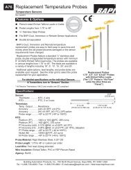
<strong>Temperature</strong> <strong>Accuracy</strong> <strong>of</strong> <strong>Thermistors</strong> <strong>and</strong> <strong>RTDs</strong>Application NotesWhat is a Thermistor how is it defined <strong>and</strong> what is its ideal accuracy?03/13/2008A thermistor is an electrical device that varies its electrical resistance with temperature (Thermistor is short for thermalresistor). The change in resistance with temperature follows the classic logarithmic curve, see figure 3.Resistance versus <strong>Temperature</strong> <strong>BAPI</strong> 10K-21,000,000.00900,000.00800,000.00Resistance in Ohms700,000.00600,000.00500,000.00400,000.00300,000.00200,000.00100,000.000.00-60 -45 -30 -15 0 15 30 45 60 75 90 105 120 135 150<strong>Temperature</strong> in degrees CelsiusFigure 3; <strong>Temperature</strong> versus Resistance for <strong>BAPI</strong> 10K-2 Thermistor<strong>Thermistors</strong> are made from mixtures <strong>of</strong> powdered metal oxides; recipes are closely guarded secrets <strong>of</strong> the variousthermistor manufacturers. The powdered metal oxides are thoroughly mixed <strong>and</strong> formed into the shape needed for thethermistor s manufacturing process. The formed metal oxides are heated until the metal oxides melt <strong>and</strong> turn into aceramic. Most thermistors are made from thin sheets <strong>of</strong> ceramic cut into individual sensors. The thermistors are finishedby putting leads on them <strong>and</strong> dipped into epoxy or encapsulated in glass.Samuel Ruben invented the thermistor in 1930. Mr. Ruben worked for the Vega Manufacturing Corporation. Vega madeguitars, banjos <strong>and</strong> recording machines. Mr. Ruben was working on electronic record stylus pickups when he noticed thatthe pickup configuration he was working on had a rather large negative temperature coefficient.<strong>Thermistors</strong> have come a long way in the past 80 years. According to a researcher at the National Institute <strong>of</strong> St<strong>and</strong>ards<strong>and</strong> Technology (NIST), glass encapsulated thermistors are more stable than <strong>RTDs</strong>. <strong>Thermistors</strong>, whether glass or epoxycoated can maintain ±0.2°C over large temperature intervals. Extra Precision (XP) thermistors maintain ±0.1°C.By the 1960s thermistors were main stream sensors. Steinhart <strong>and</strong> Hart, two researchers at the Woods HoleOceanographic Institute, published a paper defining a temperature versus resistance formula for thermistors. TheSteinhart-Hart equation has become the industry st<strong>and</strong>ard equation for thermistors.The classic Steinhart <strong>and</strong> Hart equation has the form:1/T = A 0 + A 1 (lnR) + A 3 (lnR) 3Where: T = <strong>Temperature</strong> in Kelvins (Kelvin = Celsius + 273.15)A 0 , A 1 , A 3 = Constants derived from thermistor measurementsR = Thermistor's resistance in Ohmsln = Natural Log (Log to the Napierian base 2.718281828 )In practice three thermistor resistance measurements at three defined temperature are made. These temperatures areusually the two endpoints <strong>and</strong> the center point <strong>of</strong> the temperature range <strong>of</strong> interest. The equation hits these three pointsdirectly <strong>and</strong> has a small error over the range. <strong>BAPI</strong> can provide Steinhart-Hart coefficients for the temperature range <strong>of</strong>0°C to 70°C that have uncertainties <strong>of</strong> 0.01°C or less.Building Automation Products, Inc., 750 North Royal Avenue, Gays Mills, WI 54631 USATel: +1-608-735-4800 Fax: +1-608-735-4804 E-mail:sales@bapihvac.com Web:www.bapihvac.comPage 3 <strong>of</strong> 5
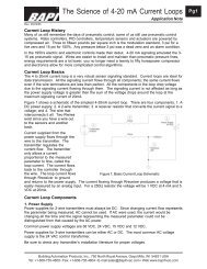
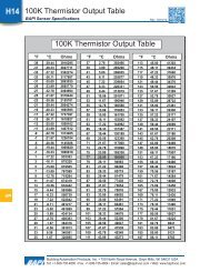
<strong>Temperature</strong> <strong>Accuracy</strong> <strong>of</strong> <strong>Thermistors</strong> <strong>and</strong> <strong>RTDs</strong>Application Notes03/13/2008There are no industry or governmental st<strong>and</strong>ards for thermistors. There are at least 5 different temperature versusresistance curves for 10K thermistors in the HVAC/R world. All the thermistors have 10,000 Ohms <strong>of</strong> resistance at 77°For 25°C, but they vary greatly the further you get away from 77°F. Both <strong>BAPI</strong> s 10K-2 <strong>and</strong> 10K-3 thermistors have 10,000Ohms <strong>of</strong> resistance at 77°F. At 32°F (0°C) the 10K-2 thermistor has 32,650 Ohms <strong>of</strong> resistance <strong>and</strong> a 10K-3 29,490Ohms. If a 10K-3 thermistor is substituted for a 10K-2 you could have 6°F <strong>of</strong> measurement error at 32°F.<strong>Thermistors</strong> have a very large resistance change with temperature. Differentiating between one degree <strong>and</strong> another isrelatively easy. This large resistance change limits the temperature range that can be resolved to a fraction <strong>of</strong> what anRTD can resolve.How do the accuracies <strong>and</strong> temperature ranges <strong>of</strong> <strong>RTDs</strong> <strong>and</strong> <strong>Thermistors</strong> compare?<strong>Thermistors</strong> are generally more accurate than Class B <strong>RTDs</strong> over the thermistors operating temperature range <strong>and</strong> similarto Class A <strong>RTDs</strong>.<strong>Temperature</strong> Sensor Errors54Uncertainty in Degrees Celsius3210-1-2-3XP ThermistorSt<strong>and</strong>ard ThermistorClass A RTDClass B RTD-4-5-200 0 200 400 600 800<strong>Temperature</strong> in Degrees CelsiusFigure 4; <strong>Accuracy</strong> Limits <strong>and</strong> Useable <strong>Temperature</strong> Ranges for <strong>Thermistors</strong> <strong>and</strong> <strong>RTDs</strong>Are there other application limits for <strong>RTDs</strong> <strong>and</strong> <strong>Thermistors</strong>?The wiring used to connect the temperature sensor to the measuring device adds resistance <strong>and</strong> measurement error.Usually 18 Gauge copper wire is used to connect sensors to their measurement devices. At 20°C (43°F) 18 Gauge wirehas a resistance <strong>of</strong> 6.4 Ohms for every 1000 feet <strong>of</strong> wire. At 140°F (70°C) 18 Gauge wire has 7.7 Ohms for every 1000feet <strong>of</strong> wire. The table below shows how much wire may be used if you wish to keep wiring error at ¼ °F or lower.Table 2; Wire lengths for ¼ °F Sensor ErrorSensor Type Wire length at 20°C Wire length at 70°C100 Ohm RTD 15 Feet 12.5 Feet1,000 Ohm RTD 150 Feet 125 Feet10K Thermistor 98,000 feet 9,090 FeetThe wiring errors in Table 2 illustrates why temperature transmitters are used with <strong>RTDs</strong>. Reasonable wiring lengths areonly permissible with transmitters. Transmitters change the RTD resistance into a 4 to 20 mA current signal proportionalto the <strong>RTDs</strong> temperature. A temperature range must be established; a 4 mA output corresponds to the minimumtemperature <strong>and</strong> 20mA corresponds to the maximum temperature. Any intermediate temperature is just a linearBuilding Automation Products, Inc., 750 North Royal Avenue, Gays Mills, WI 54631 USATel: +1-608-735-4800 Fax: +1-608-735-4804 E-mail:sales@bapihvac.com Web:www.bapihvac.comPage 4 <strong>of</strong> 5
<strong>Temperature</strong> <strong>Accuracy</strong> <strong>of</strong> <strong>Thermistors</strong> <strong>and</strong> <strong>RTDs</strong>Application Notes03/13/2008proportion from 4 mA to 20mA. Transmitters must be within 10 feet <strong>of</strong> the RTD s location. Transmitters may be up to77,000 feet from the measurement device.<strong>Temperature</strong> transmitters can have spans from 16.6°C (30°F) to 555°C (1,000°F) <strong>and</strong> low, 4mA temperatures, from -150°C (-238°F) to 482°C (900°F). For extra money <strong>RTDs</strong> <strong>and</strong> transmitters can be matched to have measurement errors<strong>of</strong> 0.05°C (0.1°F) across the span.So what sensor is better?It depends.<strong>Thermistors</strong> cost less than <strong>RTDs</strong>.<strong>Thermistors</strong> measure temperature to the same or better accuracies than <strong>RTDs</strong>.<strong>Thermistors</strong> do not need the extra cost <strong>of</strong> transmitters.<strong>RTDs</strong> have a much larger temperature measurement range than thermistors.Transmitters add at least $100 to the cost <strong>of</strong> an RTD.Building Automation Products, Inc., 750 North Royal Avenue, Gays Mills, WI 54631 USATel: +1-608-735-4800 Fax: +1-608-735-4804 E-mail:sales@bapihvac.com Web:www.bapihvac.comPage 5 <strong>of</strong> 5