Wake Encoutner Severity Assessment Based on ... - WakeNet
Wake Encoutner Severity Assessment Based on ... - WakeNet
Wake Encoutner Severity Assessment Based on ... - WakeNet
- No tags were found...

You also want an ePaper? Increase the reach of your titles
YUMPU automatically turns print PDFs into web optimized ePapers that Google loves.
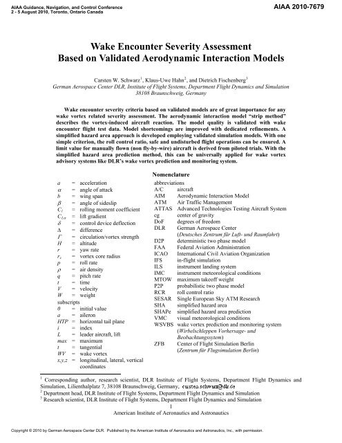
AIAA Guidance, Navigati<strong>on</strong>, and C<strong>on</strong>trol C<strong>on</strong>ference2 - 5 August 2010, Tor<strong>on</strong>to, Ontario CanadaAIAA 2010-7679<str<strong>on</strong>g>Wake</str<strong>on</strong>g> Encounter <str<strong>on</strong>g>Severity</str<strong>on</strong>g> <str<strong>on</strong>g>Assessment</str<strong>on</strong>g><str<strong>on</strong>g>Based</str<strong>on</strong>g> <strong>on</strong> Validated Aerodynamic Interacti<strong>on</strong> ModelsCarsten W. Schwarz 1 , Klaus-Uwe Hahn 2 , and Dietrich Fischenberg 3German Aerospace Center DLR, Institute of Flight Systems, Department Flight Dynamics and Simulati<strong>on</strong>38108 Braunschweig, Germany<str<strong>on</strong>g>Wake</str<strong>on</strong>g> encounter severity criteria based <strong>on</strong> validated models are of great importance for anywake vortex related severity assessment. The aerodynamic interacti<strong>on</strong> model “strip method”describes the vortex-induced aircraft reacti<strong>on</strong>. The model quality is validated with wakeencounter flight test data. Model shortcomings are improved with dedicated refinements. Asimplified hazard area approach is developed employing validated simulati<strong>on</strong> models. With <strong>on</strong>esimple criteri<strong>on</strong>, the roll c<strong>on</strong>trol ratio, safe and undisturbed flight operati<strong>on</strong>s can be ensured. Alimit value for manually flown (n<strong>on</strong> fly-by-wire) aircraft is derived from piloted trials. With thesimplified hazard area predicti<strong>on</strong> method, this can be universally applied for wake vortexadvisory systems like DLR’s wake vortex predicti<strong>on</strong> and m<strong>on</strong>itoring system.a = accelerati<strong>on</strong> = angle of attackb = wing span = angle of sideslipC l = rolling moment coefficientC L = lift gradient = c<strong>on</strong>trol device deflecti<strong>on</strong> = difference = circulati<strong>on</strong>/vortex strengthH = altituder = yaw rater c = vortex core radiusp = roll rate = air densityq = pitch ratet = timeV = velocityW = weightsubscripts0 = initial valuea = ailer<strong>on</strong>HTP = horiz<strong>on</strong>tal tail planei = indexL = leader aircraft, liftmax = maximumt = tangentialWV = wake vortexx,y,z = l<strong>on</strong>gitudinal, lateral, verticalcoordinatesNomenclatureabbreviati<strong>on</strong>sA/C aircraftAIM Aerodynamic Interacti<strong>on</strong> ModelATM Air Traffic ManagementATTAS Advanced Technologies Testing Aircraft Systemcg center of gravityDoF degrees of freedomDLR German Aerospace Center(Deutsches Zentrum für Luft- und Raumfahrt)D2P deterministic two phase modelFAA Federal Aviati<strong>on</strong> Administrati<strong>on</strong>ICAO Internati<strong>on</strong>al Civil Aviati<strong>on</strong> Organizati<strong>on</strong>IFS in-flight simulati<strong>on</strong>ILS instrument landing systemIMC instrument meteorological c<strong>on</strong>diti<strong>on</strong>sMTOW maximum takeoff weightP2P probabilistic two phase modelRCR roll c<strong>on</strong>trol ratioSESAR Single European Sky ATM ResearchSHA simplified hazard areaSHAPe simplified hazard area predicti<strong>on</strong>VMC visual meteorological c<strong>on</strong>diti<strong>on</strong>sWSVBS wake vortex predicti<strong>on</strong> and m<strong>on</strong>itoring system(Wirbelschleppen Vorhersage- undBeobachtungssytem)ZFB Center of Flight Simulati<strong>on</strong> Berlin(Zentrum für Flugsimulati<strong>on</strong> Berlin)1 Corresp<strong>on</strong>ding author, research scientist, DLR Institute of Flight Systems, Department Flight Dynamics andSimulati<strong>on</strong>, Lilienthalplatz 7, 38108 Braunschweig, Germany,2 Department head, DLR Institute of Flight Systems, Department Flight Dynamics and Simulati<strong>on</strong>3 Research scientist, DLR Institute of Flight Systems, Department Flight Dynamics and Simulati<strong>on</strong>1American Institute of Aer<strong>on</strong>autics and Astr<strong>on</strong>auticsCopyright © 2010 by German Aerospace Center DLR. Published by the American Institute of Aer<strong>on</strong>autics and Astr<strong>on</strong>autics, Inc., with permissi<strong>on</strong>.
I. Introducti<strong>on</strong>SSESSING the severity of wake vortex encounters is of high relevance for both designing any wake vortexA advisory and assistance systems and c<strong>on</strong>ducting the corresp<strong>on</strong>ding safety cases. For the design of advisory andassistance systems the severity assessment should not be of high complexity and should not require lots ofcomputati<strong>on</strong> time and input data in order to be applied in an operati<strong>on</strong>al envir<strong>on</strong>ment. This means that a certainamount of simplificati<strong>on</strong> is required. On the other hand for the safety evaluati<strong>on</strong> of any new wake vortexregulati<strong>on</strong>s, operati<strong>on</strong>al c<strong>on</strong>cepts and advisory or assistance systems a detailed analysis is required. In any case theunderlying models and simulati<strong>on</strong>s have to be validated with measurement data in order to build c<strong>on</strong>fidence.It is agreed that currently no comm<strong>on</strong>ly accepted criteria or metrics for wake vortex encounter severityassessment are available 1,2,3 although c<strong>on</strong>siderable work has been c<strong>on</strong>ducted in the last decades 4 and recently 5,6 .Currently this topic plays a role in the <str<strong>on</strong>g>Wake</str<strong>on</strong>g>Net3-Europe task group “safety assessment” and in the activitiesRECAT *1 (FAA/Euroc<strong>on</strong>trol) and SESAR.This paper presents a simplified approach for wake vortex encounter severity assessment (simplified hazardareas – SHA). The severity assessment is based <strong>on</strong> aerodynamic interacti<strong>on</strong> models, whose model quality isdiscussed and validated with test data.II. <str<strong>on</strong>g>Wake</str<strong>on</strong>g> Vortex Encounter ModelingThe essential comp<strong>on</strong>ents for wake encounter analysis are the descripti<strong>on</strong> of the vortex generati<strong>on</strong>, transport anddecay, as well as the representati<strong>on</strong> of the wake vortex induced velocity distributi<strong>on</strong>. Another important element isthe modeling of the interacti<strong>on</strong> between vortex flow disturbance and encountering aircraft. This secti<strong>on</strong> describes theselected models.A. <str<strong>on</strong>g>Wake</str<strong>on</strong>g> Vortex ModelingThe initial vortex strength (circulati<strong>on</strong>) 0 according to the KUTTA-JOUKOWSKY theorem for an aircraft(leader "L") in level flight with the weight W L , wing span b L , and airspeed V L isWLΓ0 (1)VLbL4where /4 applies for elliptical lift distributi<strong>on</strong> and is the air density. In the literature the initial vortex coreradius is specified between 1% and 5% of the generator wing span 7 . According to measurements from flight tests theinitial core radius r c0 is identified to be 3.5% of the generator wing span 8, 9r c0 = 0.035 b L (2)Vortex evoluti<strong>on</strong> (decay and transport) are modeled by the probabilistic/deterministic two phase model(P2P/D2P) depending <strong>on</strong> the atmospheric c<strong>on</strong>diti<strong>on</strong>s 10, 11 . The core radius r c is growing with increasing vortex age.Different simulati<strong>on</strong>s revealed that the core diameter has no significant effect <strong>on</strong> the upset of encountering aircraft 12,13 . Parameter variati<strong>on</strong> showed that for hazard c<strong>on</strong>siderati<strong>on</strong>s a smaller core radius for a given circulati<strong>on</strong> is ac<strong>on</strong>servative approach 14 . Therefore a c<strong>on</strong>stant core radius is used.r c = r c0 (3)The wake vortex induced velocities are calculated by superimposing two single vortices, using the analyticaltangential velocity (V t ) model of BURNHAM-HALLOCK 15 (based <strong>on</strong> ROSENHEAD 16 ), which yields good resultsfor wake vortex encounters 8, 9 .VΓr Lt2 22 rc r(4)B. Aerodynamic Interacti<strong>on</strong> Model Validated with Flight TestsThe effects <strong>on</strong> aircraft aerodynamics due to individual angle of attack variati<strong>on</strong>s induced by spatial localatmospheric flow disturbances need to be c<strong>on</strong>sidered by an Aerodynamic Interacti<strong>on</strong> Model (AIM). An accepted andeasy to apply encounter model is the Strip Model 18,19 . It is based <strong>on</strong> lifting line theory and describes the additi<strong>on</strong>alaerodynamic forces and moments acting <strong>on</strong> an aircraft in a spatial wind field, e.g. wake turbulence. The important* RECAT - Re-categorizati<strong>on</strong> of the <str<strong>on</strong>g>Wake</str<strong>on</strong>g> Turbulence Separati<strong>on</strong> Minima, Euroc<strong>on</strong>trol and FAA joint effort2American Institute of Aer<strong>on</strong>autics and Astr<strong>on</strong>autics
aerodynamic forces generating surfaces of an aircraft (wing,horiz<strong>on</strong>tal and vertical tail) are segmented into strips, Figure II-1. Well proven numbers of strips for a medium size aircraft tocover the effects of the wake vortex phenomen<strong>on</strong> are 16 for thewing, 8 for the horiz<strong>on</strong>tal tail plane and 4 for the vertical tail.At the 25% chord locati<strong>on</strong> of each strip the additi<strong>on</strong>al angles ofattack (wing, horiz<strong>on</strong>tal tail) and angles of sideslip (verticaltail) produced by the local flow disturbance are computed.Applying the respective local lift gradient C L an additi<strong>on</strong>al liftporti<strong>on</strong> is determined for each strip. These local lift incrementsare weighted in span directi<strong>on</strong> elliptically and then summarizedto get the resulting forces. Additi<strong>on</strong>ally, the corresp<strong>on</strong>dingmoments of all strips are computed from their lift incrementsand their individual lever arms with respect to the aircraft’s cg.The summary of the moment increments results in the overallmoments. No drag effects are c<strong>on</strong>sidered initially by the stripmodel, describing wake effects in 5 degrees of freedom.The validati<strong>on</strong> process of the AIM with flight test data isillustrated in Fig. II-2. The complete aerodynamic modelcomputes the sum of forces and moments of (a) the basicaircraft aerodynamic model and (b) the aerodynamic interacti<strong>on</strong>Figure II-1. Strip Model.model, which provides -forces and -moments due to wake influence. The simulati<strong>on</strong> is driven by the flight testmeasured c<strong>on</strong>trol inputs (elevator, ailer<strong>on</strong>, rudder etc.). The model outputs are compared to the corresp<strong>on</strong>dingmeasured data, which are typically linear and rotati<strong>on</strong>al accelerati<strong>on</strong>s, rotati<strong>on</strong>al rates, altitude, and velocity. It isself-evident that the basic aerodynamic model has to be of high quality to make sure that the calculated error(“model accuracy”) does not originate from this model. The required quality can <strong>on</strong>ly be achieved by tuning thebasic aerodynamic model with parameter identificati<strong>on</strong> techniques in an a-priori step using suitable flight test datathat are recorded far away from any wake influence. In such flight tests the a/c eigenmodes should be excited 20adequately to identify the respective parameters.In additi<strong>on</strong> the exact knowledge of the wakemeasuredflight testdataflightpathwakemodelparametersaccelerati<strong>on</strong>s, rates,attitude, altitude, velocityc<strong>on</strong>trolsbasicbasicA/C A/C aeroaeromodelmodelaerodynamicinteracti<strong>on</strong>modelmodelforces,moments+++ forces, moments“modelaccuracy”- modeloutputs6-DOF6-DOFA/CA/Csimulati<strong>on</strong>simulati<strong>on</strong>modelFigure II-2. Method to validate wake encounter modelsfrom flight test datavortex model parameters (strength and positi<strong>on</strong>)for each encounter is required. These modelparameters are determined also in an a-prioristep. Using flight test data of the encounteraircraft, its flight path can be rec<strong>on</strong>structed andthe corresp<strong>on</strong>ding flow angles and β can becomputed precisely without any local floweffects from wake influence taken into account.The differences between these inertial flowangles and the measured <strong>on</strong>es are used todetermine the wake characteristics.Finally, the aerodynamic interacti<strong>on</strong> model isfed with the rec<strong>on</strong>structed flight path and theaircraft’s Euler angles. This “driven mode”stabilizes the wake encounter simulati<strong>on</strong> andproved to be essential, as wake induced forcesand moments are very sensitive to small flightpath inaccuracies.The accuracy is assessed by computing thestandard deviati<strong>on</strong>s of the error between model outputs and the corresp<strong>on</strong>ding flight test data. The maximum errorsare also observed. Each degree of freedom is c<strong>on</strong>sidered separately.Applying the method of Fig. II-2, a validati<strong>on</strong> example is shown in Fig. II-3: a lateral fly-through of the twinengine turboprop Do128 aircraft (MTOW 4 t) into the wake of DLR’s twin engine jet VFW 614 ATTAS test aircraft(MTOW 21 t). This fly-through is a typical validati<strong>on</strong> example out of more than 50 encounters c<strong>on</strong>ducted in theEuropean project S-<str<strong>on</strong>g>Wake</str<strong>on</strong>g> 18,21 . Typical model outputs (red lines) in all 6 DoF are compared to the corresp<strong>on</strong>dingflight test data (black lines).3American Institute of Aer<strong>on</strong>autics and Astr<strong>on</strong>autics
Figure II-3. Do128 lateral wake flythrough:simulati<strong>on</strong> model output ( _______ )compared to flight test data ( _______ )Looking at each DoF separately, the model quality can beassessed as follows: the rolling moti<strong>on</strong> (roll rate p) and thevertical moti<strong>on</strong> (vertical accelerati<strong>on</strong> az) during a wake flythroughcan be simulated in high quality. This can bec<strong>on</strong>sidered to be an outstanding result for the strip modelquality with its widely linear structure, and also a verificati<strong>on</strong> ofthe elaborate validati<strong>on</strong> procedure. Both roll and vertical degreeof freedom are the most important inputs into todays wakehazard assessment tools. The pitching moti<strong>on</strong> (pitch rate q) isalso simulated in good quality, despite some minor deficienciesat the beginning of the wake encounter. The lateral moti<strong>on</strong>(accelerati<strong>on</strong> ay) has some minor, but tolerable discrepancies.The l<strong>on</strong>gitudinal moti<strong>on</strong> (accelerati<strong>on</strong> ax) has discrepancies asno drag effects are modelled since this degree of freedom isassumed to be of minor interest. The yawing moti<strong>on</strong> isc<strong>on</strong>sidered to be of more importance in terms of wakeencounter simulati<strong>on</strong> quality. Unfortunately, the simulatedmodel dynamics is at the wake entry opposite to what the flighttest shows. This is a typical result found in many Do128encounter validati<strong>on</strong>s. Some efforts were undertaken to furtherimprove the model quality, with special analysis in the yawingmoti<strong>on</strong>. A correlati<strong>on</strong> was found between the model faults inthe l<strong>on</strong>gitudinal axis and the yawing moti<strong>on</strong>. Obviously, drageffects have c<strong>on</strong>siderable impact <strong>on</strong> the yaw degree of freedom.So, the model was extended to c<strong>on</strong>sider drag effects. Dragdepends n<strong>on</strong>linearly <strong>on</strong> angle of attack. However, n<strong>on</strong>linearitiescannot be implemented in the strip model independent of thebasic aircraft aero model, but exactly this independency is thefundamental idea of the strip model in this applicati<strong>on</strong>. To stickto this approach, a linear formulati<strong>on</strong> with <strong>on</strong>e drag derivative,applied to each single strip, was used to c<strong>on</strong>sider wing and taildrag. Applying corresp<strong>on</strong>ding lever arms, the drag increments were also added to the yawing moment.A further model extensi<strong>on</strong> was introduced to c<strong>on</strong>sider fuselage effects. For this empirical model the fuselage isdivided typically into 20 strips (Fig. II-4), computing a wake induced local sideslip angle at each fuselage strip.Using a suitable fuselage strip derivative, the summati<strong>on</strong> of the strip increments gives a lateral fuselage force, and,c<strong>on</strong>sidering the corresp<strong>on</strong>ding lever arms, a corresp<strong>on</strong>ding fuselage yawing moment.The determinati<strong>on</strong> of the two additi<strong>on</strong>alparameters, the wing drag derivative and thexzFigure II-4. Strip model fuselage effect modellingfuselage side force derivative, was d<strong>on</strong>e applyingthe complete validati<strong>on</strong> procedure (Fig. II-2) in anoptimizati<strong>on</strong> loop to minimize the discrepanciesbetween model output and flight test data 17 . Theidentificati<strong>on</strong> process was performed using flighttest data of 23 Do128 encounters into the VFW 614ATTAS wake providing high quality flight test data. The result: both derivatives were identified to be about 0.8.Looking at the standard deviati<strong>on</strong>s of the errors between the flight test data and the simulati<strong>on</strong> output, a c<strong>on</strong>siderablemodel improvement for all analysed encounters is realized: about 51% in the yaw (r) and 48% in the l<strong>on</strong>gitudinalaxis (ax) for all 23 encounters. Through coupling effects, improvements also in the roll axis p (16%), in the lateralaxis ay (10%) and the vertical axis az (11%) are achieved.Figure II-5 shows the time histories of the encounter case already discussed in Figure II-3 but now applying thedescribed model extensi<strong>on</strong>s. Despite some discrepancies in the lateral moti<strong>on</strong>, a c<strong>on</strong>siderable improvement in thel<strong>on</strong>gitudinal axis (ax) and the yawing moti<strong>on</strong> (r) is seen. The initial opposite model reacti<strong>on</strong> in the yawing moti<strong>on</strong> isnow largely eliminated. However, <strong>on</strong>e c<strong>on</strong>straint is evident: no general formulati<strong>on</strong> was found for the semiempiricaldrag derivatives. Suitable values can be determined from flight test data applying the method described inthis paper. If those flight test data are not available, the value of 0.8 may be used, but it should be noted that thevalidity of this number has still to be proven for other aircraft.4American Institute of Aer<strong>on</strong>autics and Astr<strong>on</strong>autics
III. <str<strong>on</strong>g>Wake</str<strong>on</strong>g> Vortex Encounter <str<strong>on</strong>g>Severity</str<strong>on</strong>g> Criteri<strong>on</strong> forSimplified Hazard AreasFor operati<strong>on</strong>al applicati<strong>on</strong>s like dynamic wake vortexseparati<strong>on</strong>s a simple and robust severity criteri<strong>on</strong> is needed. Theidea is to define simplified hazard areas (SHA) around wakevortices which have to be avoided in order to ensure safety,passenger comfort and undisturbed flight operati<strong>on</strong>s (i.e. no goarounds)with a c<strong>on</strong>servative approach. The simplified hazardarea describes this regi<strong>on</strong> outside of which safe and undisturbedoperati<strong>on</strong>s are ensured 22,7 . In order to have a simple approach<strong>on</strong>ly <strong>on</strong>e parameter is selected for the definiti<strong>on</strong> of the SHA.However, the acceptable limit for this parameter which describesthe size of the SHA ought to be c<strong>on</strong>servative enough to guaranteethat no unacceptable wake vortex encounter takes placec<strong>on</strong>sidering the complete aircraft reacti<strong>on</strong>.Especially for approach and landing, which c<strong>on</strong>stitutes acapacity bottleneck, encounters with small encounter angles aretypical. Here the wake vortex induced rolling moment is thedominating effect for the encountering aircraft 21.23 . This isespecially the case for the outer regi<strong>on</strong>s of the wake vortex. Theseare relevant for the determinati<strong>on</strong> of the hazard area dimensi<strong>on</strong>s,since the core regi<strong>on</strong> has to be avoided in any case (as l<strong>on</strong>g as thevortex is not largely decayed), because the str<strong>on</strong>ger effects of thewake vortex in the core regi<strong>on</strong> cannot necessarily be compensatedfor as easily. Therefore, the definiti<strong>on</strong> of the simplified hazardareas is based <strong>on</strong> the induced rolling moment. In order to relatethe induced rolling moment to the c<strong>on</strong>trollability of theencountering aircraft it is related to the maximum roll c<strong>on</strong>trolpower 24,31 . This defines the dimensi<strong>on</strong>less wake vortex inducedroll c<strong>on</strong>trol ratio RCR.RCR = |C l,WV / C l ( a,max )| (5)This is a widespread measure for wake vortexencounter evaluati<strong>on</strong>s 25-28 . Choosing an upperRCR limit defines the SHA, (c<strong>on</strong>servatively)approximated by e.g. a rectangle (Figure III-1). Itis important to note that if this RCR limit issufficiently small, the resulting hazard area coversalso all other relevant aspects of aircraft resp<strong>on</strong>se(like aircraft attitude, accelerati<strong>on</strong>s and flight pathdeviati<strong>on</strong>s) affected by a wake vortex. Thesuitability of this approach has been shown byprevious investigati<strong>on</strong>s 22,7 . The following secti<strong>on</strong>describes the determinati<strong>on</strong> of an appropriateRCR limit.Figure II-5. Do128 lateral wake flythrough:simulati<strong>on</strong> output with wing andfuselage drag modelling ( _______ )compared to flight test data ( _______ )IV. <str<strong>on</strong>g>Severity</str<strong>on</strong>g> Criteri<strong>on</strong> for Simplified HazardAreasThe suitability of a roll c<strong>on</strong>trol ratio limit forthe assessment of wake vortex encounter severityfor simplified hazard areas was investigated withpilot-in-the-loop simulator and flight tests withthe goal to establish a roll c<strong>on</strong>trol limit to ensuresafe and undisturbed flight operati<strong>on</strong>s 22,7 .Figure III-1. <str<strong>on</strong>g>Wake</str<strong>on</strong>g> vortex induced roll c<strong>on</strong>trol ratio andsimplified hazard area (SHA, for RCR = 0.2, vortex age =50 s, 'light' behind 'medium', no turbulence) in the crosssecti<strong>on</strong> behind the vortex generating aircraft (withindicated generator wing and vortex cores).5American Institute of Aer<strong>on</strong>autics and Astr<strong>on</strong>autics
A. Validati<strong>on</strong> TrialsThe SHA RCR limit validati<strong>on</strong> trials are pilotedaircraft simulati<strong>on</strong>s. The aircraft nominal flight pathis defined al<strong>on</strong>g <strong>on</strong>e of the boundaries of the SHAfor specific maximum RCR values (compare redrectangle in Figure III-1). The experiment setup is atypical approach scenario, beginning 6 nm beforerunway threshold and c<strong>on</strong>sisting of an ILS approachand the landing (Fig. IV-1). The pilot task is to trackthe nominal ILS path following the standardapproach procedures to c<strong>on</strong>figure the aircraft forlanding, including flaps and speed settings, gear Figure IV-1. Approach scenario (side view).operati<strong>on</strong> and go-arounds if applicable. The altitudeof the wake encounter and the (relatively small)encounter angles are varied and not known to thepilots. The vortex generating aircraft is in all cases acategory 'medium' aircraft (MTOW = 94 t) with avortex age of t = 50 s and a circulati<strong>on</strong> of = 252 m 2 /s.In additi<strong>on</strong> to the recorded data the pilots giveratings after each approach sequence in fourcategories: aircraft c<strong>on</strong>trol, demands <strong>on</strong> the pilot,aircraft excursi<strong>on</strong>s from flight state and path andoverall hazard 30,31 . The rating scale (Fig. IV-2) isgraduated into four levels, with a rating of 1denoting an uncritical case and a 4 denoting an Figure IV-2. Pilot rating scale 30,31 .unacceptable <strong>on</strong>e. Ratings of 1-3 are c<strong>on</strong>sideredacceptable.Piloted aircraft simulati<strong>on</strong>s were c<strong>on</strong>ducted using fixed-base, full-flight, and in-flight simulators 22,7 . In the fullflightsimulator of the ZFB (Center of Flight Simulati<strong>on</strong> Berlin – Zentrum für Flugsimulati<strong>on</strong> Berlin) 57 analyzableapproaches with wake vortex encounters were carried out. The wake vortex induced forces and moments werepreviously recorded for defined nominal flight tracks and replayed at a defined altitude (“time fixed”) in order to flyexactly al<strong>on</strong>g the hazard area boundaries. For small flight path deviati<strong>on</strong>s which are generally the case outside ofsimplified hazard areas the resulting errors can be neglected. The simulated aircraft was a twin engine turboprop(similar to Do 228), MTOW = 6 t, ICAO category ‘light’. Visual c<strong>on</strong>diti<strong>on</strong>s were varied (VMC/IMC) and weakbackground turbulence was present.Experiments in real flight offer the most realistic simulati<strong>on</strong> envir<strong>on</strong>ment. This is achieved by means of in-flightsimulati<strong>on</strong> (IFS). The DLR research aircraft ATTAS (Advanced Technologies Testing Aircraft System) isspecifically designed for this task. The real aircraft acts like the simulated aircraft (in this case the same aircraft typeas the real aircraft since the test pilots are experienced with the aircraft type), which encounters the wake vortex. Theexperimental pilot is flying the simulated aircraft using real c<strong>on</strong>trols. These inputs are fed into the <strong>on</strong>boardcomputers stimulating the model aircraft which reacts directly to the inputs and to the effects of the virtual wakevortex flow. The resulting model aircraft states and accelerati<strong>on</strong>s are fed into the model following c<strong>on</strong>trol system.The model following c<strong>on</strong>troller generates the c<strong>on</strong>trol commands for the (real) host aircraft which are necessary tomake the host aircraft behave like the simulated aircraft. So the flight states of the host aircraft experienced by theexperimental pilot are matching the flight states of the simulated aircraft. The feasibility of wake vortex in-flightsimulati<strong>on</strong>s was previously dem<strong>on</strong>strated 29 , exhibiting a good simulati<strong>on</strong> fidelity for an RCR at least up to RCR =0.5.The encountering aircraft (ATTAS) type is a VFW 614 (ICAO class 'medium', MTOW = 21 t). <str<strong>on</strong>g>Wake</str<strong>on</strong>g> vortexencounters are c<strong>on</strong>ducted “time fixed” (explanati<strong>on</strong> see above) as well as “space fixed”. In the latter case the vortexpair is positi<strong>on</strong>ed near the nominal flight path and vortex-induced forces and moments are calculated <strong>on</strong>lineaccording to the actual aircraft positi<strong>on</strong> and attitude. This way the maximum occurring RCR value is not predefinedbut can be obtained from the recorded data. The flight test preparati<strong>on</strong> is d<strong>on</strong>e in DLR’s ATTAS fixed-base systemsimulator. These results are also taken into account for the hazard analysis.6American Institute of Aer<strong>on</strong>autics and Astr<strong>on</strong>autics
B. Safety ThresholdThe combined results fromthe above menti<strong>on</strong>ed trials 7 aredepicted in Figure IV-3. Thefigure shows the maximum rollc<strong>on</strong>trol ratio RCR which occurredduring each wake encounter vs.the respective height aboveground. The green symbolsindicate acceptable encountersand the red unacceptable <strong>on</strong>es.The database comprises <strong>on</strong>ly 114encounter events flown by 4different pilots. So the statisticalbasis is not very good. However,it can be observed that for RCRless than 0.2 no unacceptableencounters can be found. Thus,the RCR value of 0.2 is proposedas a c<strong>on</strong>servative safety thresholdfor simplified hazard areas formanually flown (n<strong>on</strong> fly-by-wire)aircraft. This is a c<strong>on</strong>servativeapproach since there are alsoacceptable encounters with RCRabove 0.2.acceptableunacceptableo IFS space fixed+ IFS time fixedx simulator space fixed□ simulator time fixedFigure IV-3. Maximum roll c<strong>on</strong>trol ratio (RCR max ) vs. encounter height 7 .V. Simplified Hazard Area Predicti<strong>on</strong> for Dynamic <str<strong>on</strong>g>Wake</str<strong>on</strong>g> Vortex Separati<strong>on</strong>sIn order to determine the actual simplified hazard area dimensi<strong>on</strong>s for given RCR limit (e.g. RCR = 0.2), aircraftpairing and vortex strength in the c<strong>on</strong>text of a dynamic wake vortex separati<strong>on</strong> advisory system a predicti<strong>on</strong> methodis applied as described in the following secti<strong>on</strong>.A. Simplified Hazard Area Predicti<strong>on</strong>The determinati<strong>on</strong> of the simplified hazard areas requires a number of input parameters and aircraft data, mainlyfor the encountering aircraft. In order to allow a broad applicability independent of available specific aircraft data, a"Simplified Hazard Area Predicti<strong>on</strong>" (SHAPe) can be applied with various levels of abstracti<strong>on</strong> 31, 14 . For the highestlevel of abstracti<strong>on</strong> the parameterizati<strong>on</strong> of aircraft data is related to <strong>on</strong>ly <strong>on</strong>e quantity, the maximum takeoff weight(MTOW). <str<strong>on</strong>g>Based</str<strong>on</strong>g> <strong>on</strong> a database of existing transport aircraft a functi<strong>on</strong>al relati<strong>on</strong>ship is established between therelevant aircraft parameters and the MTOW. This way the required input parameters for the hazard area calculati<strong>on</strong>can be determined. Because of the statistical uncertainty a worst-case approach has to be applied. For example a lowairspeed of the encounter aircraft results in a str<strong>on</strong>ger aircraft reacti<strong>on</strong> because the wake vortex induced angles ofattack are higher. So the lowest airspeed for a certain aircraft category within the database represents the respectiveworst case. This way the hazard area calculati<strong>on</strong> can be executed for any (also generic) c<strong>on</strong>venti<strong>on</strong>al transportaircraft.B. Dynamic <str<strong>on</strong>g>Wake</str<strong>on</strong>g> Vortex Separati<strong>on</strong>sDynamic wake vortex separati<strong>on</strong>s are predicted by DLR’s wake vortex predicti<strong>on</strong> and m<strong>on</strong>itoring systemWSVBS 32 where SHAPe (based <strong>on</strong> the simplified hazard area c<strong>on</strong>cept) c<strong>on</strong>stitutes a fundamental element.For the ILS approach the approach corridor can be determined (cross-secti<strong>on</strong> c<strong>on</strong>servatively approximated by arectangle), which covers the positi<strong>on</strong>s of the approaching aircraft with a certain likelihood (Figure V-1). The wakevortex evoluti<strong>on</strong> model P2P menti<strong>on</strong>ed in secti<strong>on</strong> II.A yields the probable range for the actual vortex strength forboth vortices and their probabilistic habitati<strong>on</strong> area. For the worst case at least <strong>on</strong>e vortex is exactly <strong>on</strong> the border ofthat area. For this case the simplified hazard area is superimposed with the wake vortex habitati<strong>on</strong> area which yieldsthe overall hazard area. In general this area departs from the approach corridor due to the wake vortex transport(vortex descent and wind drift). If this overall hazard area after a certain period of time t does not overlap anymore7American Institute of Aer<strong>on</strong>autics and Astr<strong>on</strong>autics
the approach corridor, a save approach is possible for thenext aircraft. This way the minimum separati<strong>on</strong> time isderived for a specific positi<strong>on</strong> al<strong>on</strong>g the approach path.The procedure can be repeated for different windowsal<strong>on</strong>g the approach corridor, to obtain a minimumseparati<strong>on</strong> for the entire approach. This method accountsfor the atmospheric c<strong>on</strong>diti<strong>on</strong>s and can be executed forany combinati<strong>on</strong> of aircraft classes (e.g. “medium”behind “heavy”) and is currently expanded to treatpairings of individual aircraft types. The weatherdependent applicati<strong>on</strong> allows for dynamic separati<strong>on</strong>minima. For a 66 days test period at FrankfurtInternati<strong>on</strong>al Airport the system ran stable andpredicti<strong>on</strong>s were verified with measurements to besafe 33 . Capacity improving c<strong>on</strong>cepts could have beenapplied 75% of the time. Air traffic managementsimulati<strong>on</strong>s show a possible capacity gain of 3%.hazard areaapproachcorridorover allhazard areawake vortexhabitati<strong>on</strong> areaFigure V-1. Approach corridor and hazard areas.VI. C<strong>on</strong>clusi<strong>on</strong>Validated models are essential for wake encounter severity assessment. Specifically the aerodynamic interacti<strong>on</strong>model “strip method” is validated with flight test data from wake vortex encounter in-flight measurements. Theunique approach of applying system identificati<strong>on</strong> for wake vortex parameter estimati<strong>on</strong> yields good results in orderto describe the wake vortex induced aircraft reacti<strong>on</strong>. Further refinements can be successfully applied to the stripmethod to overcome shortcomings. This provides a solid basis for wake vortex encounter severity c<strong>on</strong>siderati<strong>on</strong>s.The presented approach for simplified hazard areas (SHA) ensures that unacceptable wake vortex encounters can beavoided. The roll c<strong>on</strong>trol ratio is a suitable measure for wake vortex encounter severity assessment in the c<strong>on</strong>text ofwake vortex separati<strong>on</strong> predicti<strong>on</strong> with a c<strong>on</strong>servative limit value of RCR = 0.2 for manually flown (n<strong>on</strong> fly-bywire)aircraft. The "Simplified Hazard Area Predicti<strong>on</strong>" method (SHAPe), where the aircraft data are parameterizedwith respect to the maximum takeoff weight, makes the hazard area c<strong>on</strong>cept universally applicable to anyc<strong>on</strong>venti<strong>on</strong>al transport aircraft type. SHAPe represents a major element of DLR’s wake vortex predicti<strong>on</strong> andm<strong>on</strong>itoring system WSVBS for predicting safely reduced dynamic and individual wake vortex related separati<strong>on</strong>minima.AcknowledgmentsSignificant part of the presented work has been c<strong>on</strong>ducted within the DLR internal projects wake vortex II(Wirbelschleppe II) and Weather and Flying (Wetter und Fliegen) in collaborati<strong>on</strong> with numerous DLR colleagues.The funding and support is greatly acknowledged by the authors.References12345Schwarz, C., Hahn, K.-U., Holzäpfel, F., and Gerz, T., “<str<strong>on</strong>g>Wake</str<strong>on</strong>g> vortex severity assessment – a core element of the safetycase”, presentati<strong>on</strong> at the first <str<strong>on</strong>g>Wake</str<strong>on</strong>g>Net3-Europe Workshop <strong>on</strong> <str<strong>on</strong>g>Wake</str<strong>on</strong>g> Turbulence Safety in Future Aircraft Operati<strong>on</strong>s atThales University in Jouy-en-Josas, near Paris, France, <strong>on</strong> 8 - 9 Jan. 2009, http://www.wakenet3-europe.eu/index.php?id=63[cited 10 June 2010].“<str<strong>on</strong>g>Wake</str<strong>on</strong>g> Turbulence: An Obstacle to Increased Air Traffic Capacity”, Committee to C<strong>on</strong>duct an Independent <str<strong>on</strong>g>Assessment</str<strong>on</strong>g> ofthe Nati<strong>on</strong>'s <str<strong>on</strong>g>Wake</str<strong>on</strong>g> Turbulence Research and Development Program, Nati<strong>on</strong>al Research Council, ISBN: 0-309-11380-6,URL: http://www.nap.edu/catalog/12044.html [cited 10 June 2010].Elsenaar, B. (Editor), “<str<strong>on</strong>g>Wake</str<strong>on</strong>g>Net2-Europe - <str<strong>on</strong>g>Wake</str<strong>on</strong>g> Vortex Research Needs for 'Improved <str<strong>on</strong>g>Wake</str<strong>on</strong>g> Vortex Separati<strong>on</strong> Ruling' and'Reduced <str<strong>on</strong>g>Wake</str<strong>on</strong>g> Signatures' Part I”, 2006, http://www-mip.<strong>on</strong>era.fr/projets/<str<strong>on</strong>g>Wake</str<strong>on</strong>g>Net2-Europe/publicati<strong>on</strong>s.htm [cited 10 June2010], http://wakenet.eu/publicati<strong>on</strong>s [cited 10 June 2010].Hahn, K.-U., Höhne, G., and Schwarz, C., “<str<strong>on</strong>g>Wake</str<strong>on</strong>g>Net2-Europe - <str<strong>on</strong>g>Wake</str<strong>on</strong>g> Vortex Research Needs for 'Improved <str<strong>on</strong>g>Wake</str<strong>on</strong>g> VortexSeparati<strong>on</strong> Ruling' and 'Reduced <str<strong>on</strong>g>Wake</str<strong>on</strong>g> Signatures' Part II Secti<strong>on</strong> 5: <str<strong>on</strong>g>Wake</str<strong>on</strong>g> Vortex Encounter <str<strong>on</strong>g>Assessment</str<strong>on</strong>g>”, 2006,http://www-mip.<strong>on</strong>era.fr/projets/<str<strong>on</strong>g>Wake</str<strong>on</strong>g>Net2-Europe/publicati<strong>on</strong>s.htm [cited 10 June 2010], http://wakenet.eu/publicati<strong>on</strong>s[cited 10 June 2010].Barnes, S., “Project Status: Characterizing <str<strong>on</strong>g>Wake</str<strong>on</strong>g> Vortex Encounters for Hazard Analysis / Safety Management SystemPurposes”, presentati<strong>on</strong> at <str<strong>on</strong>g>Wake</str<strong>on</strong>g>Net-USA meeting 17 - 18 March, 2010, Miami Springs, Florida, USA.8American Institute of Aer<strong>on</strong>autics and Astr<strong>on</strong>autics
6Amelsberg, S., “<str<strong>on</strong>g>Wake</str<strong>on</strong>g> vortex encounter severity criteria for take-off and departure”, EU project CREDOS deliverable D3-5,2009, http://www.euroc<strong>on</strong>trol.int/eec/credos/public/standard_page/deliverables.html [cited 10 June 2010].7Hahn, K.-U., and Schwarz, C. (2007) “Safe Limits for <str<strong>on</strong>g>Wake</str<strong>on</strong>g> Vortex Penetrati<strong>on</strong>”, 2007 AIAA Guidance, Navigati<strong>on</strong> andC<strong>on</strong>trol C<strong>on</strong>ference and Exhibit Proceedings (AIAA-2007-6871). AIAA 2007 Guidance, Navigati<strong>on</strong> and C<strong>on</strong>trol C<strong>on</strong>ferenceand Exhibit , 20 - 23 Aug. 2007, Hilt<strong>on</strong> Head, South Carolina (USA).8Jatega<strong>on</strong>kar, R., Fischenberg, D., and Gruenhagen, W. v., “Aerodynamic Modeling and System Identificati<strong>on</strong> from FlightData – Recent Applicati<strong>on</strong>s at DLR”, Journal of Aircraft, Vol. 41, No. 4, July – August 2004, p. 687, 2004.9Fischenberg, D., “Bestimmung der Wirbelschleppencharakteristik aus Flugmessdaten” (“Determinati<strong>on</strong> of <str<strong>on</strong>g>Wake</str<strong>on</strong>g> VortexCharacteristics from Flight Test Data”), German Aerospace C<strong>on</strong>gress, Stuttgart, 23 - 26 Sept. 2002, DGLR-JT2002-170,DGLR-Jahrestagung 2002, Jahrbuch. B<strong>on</strong>n: Deutsche Gesellschaft für Luft- und Raumfahrt, 2002.10 Holzäpfel, F., “Probabilistic Two-Phase <str<strong>on</strong>g>Wake</str<strong>on</strong>g> Vortex Decay and Transport Model”, Journal of Aircraft, Vol. 40, No. 2,March - April 2003, 2003.11 Holzäpfel, F., and Robins, R. E., “Probabilistic Two-Phase Aircraft <str<strong>on</strong>g>Wake</str<strong>on</strong>g> Vortex Model: Applicati<strong>on</strong> and <str<strong>on</strong>g>Assessment</str<strong>on</strong>g>”,Journal of Aircraft, Vol. 41, No. 5, 2004.12 Samm<strong>on</strong>ds, R. I., Stinnet jr, G. W., and Larsen, W. E., “Criteria Relating <str<strong>on</strong>g>Wake</str<strong>on</strong>g> Vortex Encounter Hazard to AircraftResp<strong>on</strong>se”, Journal of Aircraft, Vol. 14, No. 10, Oct 1977.13 Loucel, R. E., and Crouch, J. D., “Flight-simulator study of airplane encounters with perturbed trailing vortices”, AIAAAerospace Sciences Meeting and Exhibit, 5 - 8 Jan. 2004, Reno, Nevada, USA, AIAA 2004-1074, 2004.14 Schwarz, C., and Hahn, K.-U., “Gefährdung beim Einfliegen in Wirbelschleppen” (“Hazard of <str<strong>on</strong>g>Wake</str<strong>on</strong>g> Vortex Encounters”),German Aerospace C<strong>on</strong>gress, Munich, 17 - 20 Nov. 2003, DGLR-JT2003-242, DGLR-Jahrestagung, Jahrbuch 2003. B<strong>on</strong>n:Deutsche Gesellschaft für Luft- und Raumfahrt, 2003.15 Burnham, D., and Hallock, J. N., Chicago M<strong>on</strong>oacoustic Vortex Sensing System Vol. 4, <str<strong>on</strong>g>Wake</str<strong>on</strong>g> Vortex Decay, Springfield,VA, Nati<strong>on</strong>al Informati<strong>on</strong> Service (1982).16 Rosenhead, L., “The Formati<strong>on</strong> of Vortices from a Surface of Disc<strong>on</strong>tinuity”, Proceedings Royal Society of L<strong>on</strong>d<strong>on</strong>, Ser. A.,Vol. 134: p.170-192, 1932.17 Fischenberg, D., “A Method to Validate <str<strong>on</strong>g>Wake</str<strong>on</strong>g> Vortex Encounter Models from Flight Test Data”, 27th ICAS c<strong>on</strong>ference,Nice, France, 2010 (submitted for publicati<strong>on</strong>).18 Fischenberg, D., “S-WAKE Results of Flight Test Data Analysis”, DLR internal report IB 111-2002/11 & EU project S-<str<strong>on</strong>g>Wake</str<strong>on</strong>g> TN-222-1, 2002.19 McCormick, B., Aerodynamics, Aer<strong>on</strong>autics, and Flight Mechanics, John Wiley & S<strong>on</strong>s, Inc., ISBN 0-471-57506-2, 1995.20 Jatega<strong>on</strong>kar, R. V., Flight Vehicle System Identificati<strong>on</strong>: A Time Domain Methodology, Progress in Astr<strong>on</strong>autics andAer<strong>on</strong>autics Series, Vol. 216, Published by AIAA, ISBN-10: 1-56347-836-6, 2006.21 de Bruin, A., “S-<str<strong>on</strong>g>Wake</str<strong>on</strong>g> <str<strong>on</strong>g>Assessment</str<strong>on</strong>g> of <str<strong>on</strong>g>Wake</str<strong>on</strong>g> Vortex Safety – Publishable Summary Report”, EU project S-<str<strong>on</strong>g>Wake</str<strong>on</strong>g>, NLR-TP-2003-243, 2003.22 Schwarz, C., and Hahn, K.-U., “Full-flight simulator study for wake vortex hazard area investigati<strong>on</strong>”, Aerospace Scienceand Technology, 10 (2) , pp. 136-143. Elsevier, 2006. DOI: 10.1016/j.ast.2005.09.005.23 Hallock, J.N., and Eberle, W.R., Aircraft <str<strong>on</strong>g>Wake</str<strong>on</strong>g> Vortices: A State-of-the-Art Review of the United States R&D Program, U.S.Department of Transportati<strong>on</strong> (DOT), Federal Aviati<strong>on</strong> Administrati<strong>on</strong> (FAA), Report No. FAA-RD-77-23, February 1977.24 Hahn, K.-U., “Coping with <str<strong>on</strong>g>Wake</str<strong>on</strong>g> Vortex”, 23rd Internati<strong>on</strong>al C<strong>on</strong>gress of Aer<strong>on</strong>autical Sciences, Tor<strong>on</strong>to (Canada), 8 - 13Sept. 2002, ICAS, 23rd Internati<strong>on</strong>al C<strong>on</strong>gress of Aer<strong>on</strong>autical Sciences Proceedings, p. 732.1-732.14, 2002.25 Rossow, V. J., and Tinling, B. E., “Research <strong>on</strong> Aircraft/Vortex-<str<strong>on</strong>g>Wake</str<strong>on</strong>g> Interacti<strong>on</strong>s to Determine Acceptable Level of <str<strong>on</strong>g>Wake</str<strong>on</strong>g>Intensity”, Journal of Aircraft, Vol. 25, No. 6, 1988.26 Stewart, E. C., “A piloted simulati<strong>on</strong> study of wake turbulence <strong>on</strong> final approach”, AIAA Paper 98-4339, Atmospheric FlightMechanics, 10 - 12 Aug. 1998, Bost<strong>on</strong>, MA, United States, 1998.27 Luckner, R., Höhne, G., and Fuhrmann, M., “Hazard Criteria for <str<strong>on</strong>g>Wake</str<strong>on</strong>g> Vortex Encounters during Approach”, AerospaceScience and Technology, Vol. 8, No. 8 (673–687), 2004, DOI: 10.1016/j.ast.2004.06.008.28 Höhne, G., Reinke, A., and Verbeek, M., “<str<strong>on</strong>g>Wake</str<strong>on</strong>g> Vortex Encounter Flight Simulati<strong>on</strong>: Metrics, Hazard Criteria, and Influenceof Cockpit Moti<strong>on</strong>s”, EU project S-<str<strong>on</strong>g>Wake</str<strong>on</strong>g> Technical Note TN-320-1-v1, Airbus Deutschland, 2002.29 Reinke, A., Leißling, D., and Bauschat, J.-M., “Simulati<strong>on</strong> des Einflugs in Wirbelschleppen mit dem ATTAS Flugsimulator”(“Simulati<strong>on</strong> of wake vortex encounters with ATTAS flight simulator”), German Aerospace C<strong>on</strong>gress, Munich, 17 - 20 Nov.2003, DGLR-JT2003-245.30 Hahn, K.-U., Schwarz, C., and Kloidt, S., “Full-Flight Simulatorstudie zur Verifizierung v<strong>on</strong> Wirbelschleppen-Gefährdungsraumgrenzen” (“Full-Flight Simulator Study for Verificati<strong>on</strong> of <str<strong>on</strong>g>Wake</str<strong>on</strong>g> Vortex Hazard Area Boundaries”), DLRinternal report IB 111-2004/42, DLR Institute of Flight Systems, Braunschweig, 2004.31 Hahn, K.-U., Schwarz, C., and Friehmelt, H., “A Simplified Hazard Area Predicti<strong>on</strong> (SHAPe) Model for <str<strong>on</strong>g>Wake</str<strong>on</strong>g> VortexEncounter Avoidance”, 24th Internati<strong>on</strong>al C<strong>on</strong>gress of Aer<strong>on</strong>autical Sciences (ICAS), Yokohama (Japan), 29 Aug. - 3 Sept.2004.32 Holzäpfel, F., Gerz, T., Frech, M., Tafferner, A., Köpp, F., Smalikho, I., Rahm, S., Hahn, K.-U., and Schwarz, C., “The wakevortex predicti<strong>on</strong> and m<strong>on</strong>itoring system WSVBS Part I: Design”, Air Traffic C<strong>on</strong>trol Quarterly, 17 (4), pp. 301-322, 2009.33 Gerz, T., Holzäpfel, F., Gerling, W., Scharnweber, A., Frech, M., Kolber, K., Dengler, K., and Rahm, S., “The wake vortexpredicti<strong>on</strong> and m<strong>on</strong>itoring system WSVBS Part II: Performance and ATC integrati<strong>on</strong> at Frankfurt airport”, Air TrafficC<strong>on</strong>trol Quarterly, 17 (4), pp. 323-346, 2009.9American Institute of Aer<strong>on</strong>autics and Astr<strong>on</strong>autics