INSTALLATION MANUAL - Daikin AC
INSTALLATION MANUAL - Daikin AC
INSTALLATION MANUAL - Daikin AC
- No tags were found...

Create successful ePaper yourself
Turn your PDF publications into a flip-book with our unique Google optimized e-Paper software.
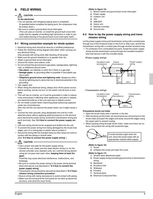
6. FIELD WIRINGCAUTIONTo the electrician• Do not operate until refrigerant piping work is completed.(If operated before complete the piping work, the compressor maybe broken down.)• Be sure to install a ground fault circuit interrupter.(This unit uses an inverter, so install the ground fault circuit interrupterthat be capable of handling high harmonics in order to preventmalfunctioning of the ground fault circuit interrupter itself.)6-1 Wiring connection example for whole system• Electrical wiring work should be done by a certified professional.• Follow the “Electrical wiring diagram face plate” when carrying outany electrical wiring.Only proceed with wiring work after blocking off all power.• Make sure the ground resistance is no greater than 4Ω .• Attach a ground fault circuit interrupter.• Ground the indoor and outdoor units.• Do not connect the ground wire to gas pipes, sewage pipes, lightningrods, or telephone ground wires.• Gas pipes: can explode or catch fire if there is a gas leak.• Sewage pipes: no grounding effect is possible if hard plastic pipingis used.• Telephone ground wires and lightning rods: dangerous whenstruck by lightning due to abnormal rise in electrical potential in thegrounding.• Use copper wire.• When doing the electrical wiring, always shut off the power sourcebefore working, and do not turn on the switch until all work is complete.• This unit has an inverter, so it must be grounded in order to reducenoise and prevent it affecting other appliances, and also to releaseany electrical build-up in the unit case due to leaked current.• Do not install a power-factor improving phase-advancing capacitorunder any circumstances.(Not only will this not improve the power factor, but it might cause afire.)• Connect the wire securely using designated wire and fix it withattached clamp without applying external pressure on the terminalparts (terminal for power wiring, terminal for transmission wiring andearth terminal). See “6-3 How to connect the power supply wiring”.• Left-over wiring should not be wrapped and stuffed into the unit.• To prevent the power wiring from being damaged by the knock holeedges, put it in a wiring pipe or plastic tube to protect it.• Secure the wiring with the included clamp so that it does not come incontact with the piping or shutoff valve.(See “6-3 How to connect the power supply wiring”.)CAUTION• Use a power wire pipe for the power supply wiring.• Outside the unit, make sure the weak electric wiring (i.e. for theremote controller cord, between units, etc.) and the strong electricwiring do not pass near each other, keeping them at least 2in.apart.Proximity may cause electrical interference, malfunctions, andbreakage.• Be sure to connect the power wiring to the power wiring terminalblock and secure it as described in “6-3 How to connect thepower supply wiring”.• Transmission wiring should be secured as described in “6-4 Transmissionwiring connection procedure”.• Secure wiring with clamp (accessory) to avoid contact with piping.• Make sure the wiring and the front panel do not stick up above thestructure, and close the cover firmly.(Refer to figure 15)1. Branch switch and ground fault circuit interrupter2. Power supply3. Outdoor unit4. 16V5. 208/230V6. Indoor unit7. Remote controller8. Ground wire6-2 How to lay the power supply wiring and transmissionwiringLet the power supply wiring and transmission wiring with a conduit passthrough one of the knockout holes on the front or side cover, and let thetransmission wiring with a conduit pass through another knockout hole.• For protection from uninsulated live parts, thread the power supplywiring and the transmission wiring through the included insulationtube and secure it with the included clamp.Insulation tube(accessory)Ground wireInsulation tube(accessory)Clamp(accessory)2in.ormoreClamp(accessory)(3in.)(3in.)Power supplywiring(5/8in.) (5/8in.)TransmissionwiringPrecautions knock out holes• Open the knock holes with a hammer or the like.• After knocking out the holes, we recommend you remove burrs in theknock holes and paint the edges and areas around the edges usingthe repair paint to prevent rusting.• When passing wiring through knock holes, make sure there are noburrs, and protect the wiring with protective tape.BurrIf small animals might enter theunit, block the knock holes with anappropriate material (field supply).(Refer to figure 16)1. Screw2. Unfasten the screw and open the cover.(Refer to figure 17)1. Shutoff valve attachment plate2. Power supply wiring (including ground wire) or transmissionwiring.3. Backward4. Knockout hole5. Sideways6. Forward7. Terminal block8. Electrical Component BoxEnglish 6