Measuring Module M 700® PA 700(X) - Mettler Toledo
Measuring Module M 700® PA 700(X) - Mettler Toledo
Measuring Module M 700® PA 700(X) - Mettler Toledo
- No tags were found...
Create successful ePaper yourself
Turn your PDF publications into a flip-book with our unique Google optimized e-Paper software.
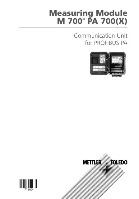
<strong>Measuring</strong> <strong>Module</strong>M <strong>700</strong> ®<strong>PA</strong> <strong>700</strong>(X)Communication Unitfor PROFIBUS <strong>PA</strong>
WarrantyDefects occurring within 1 year from delivery date shall be remedied free of charge at our plant(carriage and insurance paid by sender). Sensors, fittings, and accessories: 1 year.©2007 Subject to change without noticeReturn of products under warrantyPlease contact our Service Team before returning a defective device. Ship the cleaned device tothe address you have been given. If the device has been in contact with process fluids, it must bedecontaminated/disinfected before shipment. In that case, please attach a corresponding certificate,for the health and safety of our service personnel.DisposalPlease observe the applicable local or national regulations concerning the disposal of“waste electrical and electronic equipment”.TrademarksThe following registered trademarks are used in this instruction manualwithout further markingSMARTMEDIA ®is a registered trademark of Toshiba Corp., JapanFOUNDATION FIELDBUSis a trademark of Fieldbus Foundation, Austin, USA<strong>Mettler</strong>-<strong>Toledo</strong> AG,Process Analytics, Industrie Nord, CH-8902 Urdorf,Tel. +41 (44) 729 62 11 Fax +41 (44) 729 26 36Subject to technical changes.
ContentsM <strong>700</strong> <strong>PA</strong> <strong>700</strong> <strong>Module</strong>Explanation of EC 400 Messages: Failure ............................................. 29DI 4: EC 400 Step ............................................................................... 29DO Function Blocks ....................................................................................30DO 1: HOLD Control ........................................................................... 30DO 2: <strong>PA</strong>RSET...................................................................................... 30DO 3: EC 400 Control ......................................................................... 31DO 4: LOCK Control ........................................................................... 31Configuration Data ....................................................................................32Analog Input blocks (1 ... 8) ......................................................................33Discrete Input Blocks (1 ...4) ......................................................................34Discrete Output Blocks (1 ... 4) ..................................................................35<strong>PA</strong> Slot Model ............................................................................................36PB Block Parameters ..................................................................................37TB Analyzer Block Parameters ....................................................................39AI Function Block Parameters .....................................................................41Defaults & Writable Ranges .......................................................................41DI Function Block Parameters .....................................................................44DI Function Block Parameters .....................................................................45DO Function Block Parameters ...................................................................46AO Function Block Parameters ...................................................................48Calibration Record Parameters ...................................................................49Menu Selection ............................................................................ 61Passcode Entry ............................................................................. 62Changing a passcode .......................................................................... 62Passcode lost ....................................................................................... 62Function Control Matrix ............................................................................63Pressure Compensation via Bus (AO1)....................................... 64Diagnostics: Bus Monitor ...........................................................................65Bus Monitor ..............................................................................................66Specifications ............................................................................... 67Index ............................................................................................. 735
Intended UseThe module is a communication unit for PROFIBUS-<strong>PA</strong> and allows digitalcommunication via current modulation.The <strong>PA</strong> <strong>700</strong>X module is intended for operation in locations subject to explosionhazards which require equipment of Group II, device category 2(1), gas/dust.Conformity with FDA 21 CFR Part 11In their directive “Title 21 Code of Federal Regulations, 21 CFR Part 11,Electronic Records; Electronic Signatures“ the US American health agencyFDA (Food and Drug Administration) regulates the production and processingof electronic documents for pharmaceutical development and production.This results in requirements for measuring devices used for correspondingapplications. The following features ensure that the M <strong>700</strong>(X) modularprocess analysis system meets the demands of FDA 21 CFR Part 11:Electronic SignatureAccess to the device functions is regulated and limited by individually adjustablecodes – “Passcodes“. This prevents unauthorized modification of devicesettings or manipulation of the measurement results. Appropriate use ofthese passcodes makes them suitable as electronic signature.Audit Trail LogEvery change of device settings can be automatically recorded and documentedin the Audit Trail Log on the SmartMedia card. The recording can beencrypted.6
Safety InformationApplication in Hazardous LocationsCaution!Never try to open the module! If a repair should be required, return themodule to our factory.If the specifications in the instruction manual are not sufficient for assessingthe safety of operation, please contact the manufacturer to make sure thatyour intended application is possible and safe.Be sure to observe during installation:• Switch off power supply before replacing or inserting a module.• Before commissioning it must be proved that the device may be connectedwith other equipment.Application in Hazardous Locations:<strong>PA</strong> <strong>700</strong>X <strong>Module</strong>When using the <strong>PA</strong> <strong>700</strong> X module, the stipulations for electrical installationsin hazardous areas (EN 60079-14) must be observed. When installing thedevice outside the range of applicability of the 94/9/EC directive, the appropriatestandards and regulations in the country of use must be observed.The module has been developed and manufactured in compliance with theapplicable European guidelines and standards.Compliance with the European Harmonized Standards for use in hazardouslocations is confirmed by the EC-Type-Examination Certificate.Compliance with the European guidelines and standards is confirmed by theEC Declaration of Conformity.There is no particular direct hazard caused by the operation of the device inthe specified environment.7
Software Version<strong>PA</strong> <strong>700</strong>(X) <strong>Module</strong>Device Software M <strong>700</strong>(X)The <strong>PA</strong> <strong>700</strong>(X) module is supported by software version 5.0 or higher.<strong>Module</strong> software version 2.x requires device software version 7.x.<strong>Module</strong> Software COM<strong>PA</strong> 3400(X)-081Software version 1.3 01.06.2004Software version 2.2 02.04.2007Query actual device/module softwareWhen the analyzer is in measuring mode:Press menu key, open Diagnostics menu.Menu DisplayDevice description<strong>Module</strong><strong>Module</strong> FRONT <strong>700</strong>-011Operating panelHardware: 1, Software: 7.0Serial number 0000815FRONTReturnBASE0.003mS/cm22.7 °COptionsDevice descriptionProvides information about allmodules installed: <strong>Module</strong> type andfunction, serial number, hardwareand software version and deviceoptions.Select the different modules (FRONT,BASE, slots 1 - 3) using the arrowkeys.8
Modular ConceptBasic Unit, <strong>Measuring</strong> <strong>Module</strong>, Additional FunctionsThe M <strong>700</strong>(X) is an expandable modular process analysis system.The basic unit (FRONT and BASE modules) provides three slots which can beequipped by the user with any combination of measuring or communicationmodules. The software capabilities can be expanded by additional functions(options). Additional functions must be ordered separately. They are suppliedwith a device-specific TAN for function release.M <strong>700</strong>(X) Modular Process Analysis SystemAdditionalfunctionsActivation via devicespecificTAN<strong>Measuring</strong> modules• pH / ORP / Temp• 0 2 /Temp• Noncontacting conductivity/Temp• Contacting conductivity/TempSmartMedia cardData recording3 module slotsfor free combination ofmeasuring andcommunication modulesCommunication modules• OUT (additional switching andcurrent outputs)• PID (analog and digital controller)• Profibus <strong>PA</strong>• Foundation Fieldbus• EC 400 probe controllerDocumentationThe basic unit is accompanied by a CD-ROM containing the completedocumentation.Latest product information as well as instruction manuals for earlier softwarereleases are available at www.mtpro.com.9
Short DescriptionShort Description: FRONT <strong>Module</strong>4 captive screwsfor opening the analyzer(Caution! Make sure that the gasket betweenFRONT and BASE is properly seated and clean!)Transflective LC graphic display(240 x 160 pixels)white backlighting, high resolutionand high contrast.Measurement display24.0°C%Air°C25.8°CUser interfacewith plaintext menus asrecommended by NAMUR.Menu texts can be switched to:German, English, French, Italian,Swedish, and Spanish.Intuitively acquirable menu logic,based on Windows standards.Secondary displays2 softkeyswith context-sensitive functions.Red LEDsignals failure (On) ormaintenance request/function check(flashing) according to NE 44.Green LEDVoltage supply okayControl panel3 function keys(menu, meas, enter)and 4 arrow keys for menu selectionand data entries5 self-sealing cable glandsM20 x 1.5for entry of voltage supply and signal lines10
Short Description: Menu StructureBasic Functions: Calibration, Maintenance, Parameter Setting, Diagnostics3Menu groups<strong>Measuring</strong>12Calibration Maintenance Parameter setting DiagnosticsPasscode:1147 2958 1246Operator level41989Administrator levelSelection offurther menuitems:<strong>Module</strong> 1<strong>Module</strong> 2<strong>Module</strong> 35 6BASE<strong>Module</strong> 1<strong>Module</strong> 2<strong>Module</strong> 3SYSTEMFRONTBASE<strong>Module</strong> 1<strong>Module</strong> 2<strong>Module</strong> 3Legend:1) Pressing the menu key accesses menu selection.2) Pressing the meas key returns to measurement.3) Menu groups are selected using the arrow keys.4) Press enter to confirm, enter passcode.5) Further menu items are displayed.6) Selected functions of the Diagnostics menu can berecalled via softkey even when in measuring mode.Message listPoint of measdescriptionLogbookDevice descriptionFRONTBASE<strong>Module</strong> 1<strong>Module</strong> 2<strong>Module</strong> 311
Short Description: FRONT <strong>Module</strong>View into the open device (FRONT module)Slot for SmartMedia card• Data recordingThe SmartMedia card expands themeasurement recorder capacity to> 50000 records.• Exchange of parameter sets5 parameter sets can be stored onthe SmartMedia card. The 2 internalparameter sets can be switched byremote control.Configurations can be transmittedfrom one analyzer to the other.• Function expansionsare possible with additional softwaremodules, which are released usingtransaction numbers (TAN)• Software updatesTerminal platesof “hidden” modulesEach module comes with an adhesivelabel containing the contact assignments.This label should be sticked to the innerside of the front (as shown). Then, theterminal assignments remain visible evenif further modules are inserted.Replacing the front modulePull off power cord and ground wire.To separate the FRONT modulefrom the BASE module, turn theretaining screws of the pivot hinge by90°.The circumferential sealingguarantees IP 65 protection and allowsspray cleaning / disinfection.Caution! Keep clean!12
Short Description: BASE <strong>Module</strong>View into the open device (BASE module, 3 function modules installed)<strong>Module</strong> equipment<strong>Module</strong> identification: Plug & Play.Up to 3 modules can be combined asdesired. Several input and communicationmodules are available.BASE module2 current outputs (free assignment ofprocess variable) and 4 relay contacts,2 digital inputs.VariPower broad-range power supply,20 ... 265 V AC/DC, suitable for all publicmains supplies in the world.Power supply units, IS version:100 ... 230 V AC or24 V AC/DCWarning!Do not touch the terminal compartment, there may bedangerous contact voltages!Important notice concerning SmartMedia cardThe SmartMedia card may be inserted or replaced with the power supplyswitched on. Before a memory card is removed, it must be “closed” in themaintenance menu. When closing the device, make sure that the sealing isproperly seated and clean.13
PROFIBUS TechnologyPROFIBUS is a digital communication system that connects different fielddevices over a common cable and integrates them into a control system. Inthe long term, PROFIBUS will replace the 4-20mA technology, which onlysupplies pure measured values. Advantages of the PROFIBUS technology are:•••easy and cost-saving cablingconvenient operation over a central control stationtransmission, evaluation, and control of high amounts of data from fielddevice to control station.devices installed in hazardous locations are configured and maintainedfrom the control station•PROFIBUS is the leading open fieldbus system in Europe. Its application rangecovers manufacturing, process, and building automation. As open fieldbusstandard to EN 50170 and IEC 61158, PROFIBUS ensures communication ofdifferent devices over one bus. The PROFIBUS User Organization (PNO) providesfor further development and maintenance of the PROFIBUS technology.It combines the interests of users and manufacturers.Variants and Basic CharacteristicsPROFIBUS determines the technical and functional characteristics of a serialbus system. There are three PROFIBUS variants:• PROFIBUS-DP (decentralized peripherals)Tailored for communication of automation systems and distributed peripherals.RS 485 standard with transmission rates up to 12 MBits/sec• PROFIBUS-<strong>PA</strong> (process automation)Dedicated to the process industry. It permits connection of sensors andactuators to a common bus even in hazardous locations. PROFIBUS-<strong>PA</strong> hasa transmission rate of 31.25 kBits/sec.14
PROFIBUS TechnologyPROFIBUS distinguishes between two types of devices:• MastersControl the data traffic on the bus. They send messages without externalrequest.• SlavesPeripheral devices such as valves, drives, transmitters, and analyzers. Theycan react acyclically to servicing, configuration and diagnostic tasks of themaster. The central controller cyclically reads the measurement data withstatus.Definitions for PROFIBUS-<strong>PA</strong>The bus protocol defines type and speed of the data exchange betweenmaster and slave devices and determines the transmission protocol of therespective PROFIBUS system.PROFIBUS-<strong>PA</strong> permits cyclic and acyclic services.• Cyclic services are used for transmission of measurement data and actuatingcommands with status information.• Acyclic services are used for device configuration, maintenance and diagnosticsduring operation.The <strong>PA</strong> 3.0 device profile defines the device class and typical functionalitieswith parameters, ranges, and limit values.The FISCO model developed by the German PTB for hazardous locations permitsconnection of several devices to one common bus and defines permissiblelimits for device and cable parameters.15
Terminal Plate<strong>PA</strong> <strong>700</strong>(X) <strong>Module</strong>Terminal Plate <strong>PA</strong> <strong>700</strong> <strong>Module</strong>:Terminal Plate <strong>PA</strong> <strong>700</strong>X <strong>Module</strong>:Attaching the Terminal PlatesThe terminal plates of the lower modulescan be sticked to the inner side of the door.This facilitates maintenance and service.16
Inserting the <strong>Module</strong>Thanks to the staggered arrangement ofconnectors and fastening screws the terminalstrips of all modules are easy to access.Make sure that the cableglands are tightly closed toprotect against humidity.1.2.3.4.5.6.7.8.9.Switch off power supplyOpen the device (loosen the 4 screws at the front)Place module in slot (D-SUB connector)Tighten fastening screws of the moduleConnect signal linesClose device, tighten screws at the frontSwitch on power supplyAssigning process variables to AI blocks on the deviceSet parameters17
PROFIBUS <strong>PA</strong> InstallationBasic build-up of a PROFIBUS system:Control roomPROFIBUS-DPPROFIBUS-<strong>PA</strong>e.g. M <strong>700</strong>(X)with module<strong>PA</strong> <strong>700</strong>(X)Slave 1Slave 2...... ..... ..... Slave nElectrical connection between module and PROFIBUS <strong>PA</strong> is in accordancewith the PROFIBUS Guideline, Order No. 2.092 (www.profibus.com).PROFIBUS cable<strong>PA</strong>+ (red)<strong>PA</strong> <strong>700</strong>(X) <strong>Module</strong>12<strong>PA</strong>- (green)13Shield1418
Physical BlockGlobal Status<strong>Module</strong> Selection<strong>Module</strong> I<strong>Module</strong> IICalc. Block ICalc. Block IIProcess Variable SelectionATB 1Analyzer TransducerBlockATB 2Analyzer TransducerBlockATB 3Analyzer TransducerBlockATB 4Analyzer TransducerBlockAI 1Analog InputFunction BlockProtocolsCalibrationAI 2Analog InputFunction BlockAI 3Analog InputFunction BlockAI 4Analog InputFunction Block<strong>Module</strong> Selection<strong>Module</strong> I<strong>Module</strong> IICalc. Block ICalc. Block IIProcess Variable SelectionATB 5Analyzer TransducerBlockATB 6Analyzer TransducerBlockATB 7Analyzer TransducerBlockATB 8Analyzer TransducerBlockAI 5Analog InputFunction BlockProtocolsCalibrationAI 6Analog InputFunction BlockAI 7Analog InputFunction BlockAI 8Analog InputFunction BlockPROFIBUS <strong>PA</strong>Meas. Value CorrectionEC 400 StatusCONTACT StatusEC 400 MessageEC 400 StepHOLD Control<strong>PA</strong>RSETEC 400 ControlLOCK ControlAOAnalog OutputDI 1DI 2DI 3DI 4DO 1DO 2DO 3DO 4
Communication ModelSee diagram on previous sideThe device parameters are sorted in three types of blocks:Physical Block (PB)This block contains the general parameters which apply to the whole device.Transducer Blocks (TB 1 ... TB 8)8 analog blocks. They contain measurement parameters (process variable,temperature) according to the PROFIBUS-<strong>PA</strong> Profile 3.0 specification.Function Blocks8 analog input blocks (AI1..4, AI5..8, for scaling measured values),4 digital output blocks (DO 1 ... DO 4, for control signals)4 digital input blocks (DI 1 ... DI 4, for status messages).1 analog output block (AO 1) for analog compensation signals,e.g. O 2 process pressure.Physical Block (PB)This block contains the device-specific parameters (model designation, manufacturerID, serial number...) and controls basic device functions such as:• Write protection(“WRITE_LOCKING” parameter) Enables or locks acyclic services(maintenance, configuration).• Blocking operator access to the device(“LOCAL_OP_ENA” parameter)Enables or locks access via the user interface on the device.Notice:When communication fails for more than 30 seconds,the device automatically switches to local access.• Reset(“FACTORY_RESET” parameter)Caution – data loss!Resets all configuration values to factory setting.20
Analog Input blocksAnalog Input BlocksThe module provides 8 analog input blocks (AI 1 ... AI 8).They are divided into two groups (channels):AI 1..4: Channel 1AI 5.0.8: Channel 2Each channel can be assigned to one measuring module (or CalculationBlock). The "AI 1..4 configuration" ("AI 5..8 configuration") menu only displaysthose measured values which are provided by the selected measuringmodule. Both channels can also be assigned to the same measuring module.For configuration on the device, see Page 23.An Analog Input Block contains the signal processing options for theprocess variable supplied from the Transducer Block.The following parameters are available:21
Analog Input BlocksFunction Parameter RemarkChannelselectionCHANNELDetermined by the assignment ofprocess value to AI block in the device(see Page 22)Simulation SIMULATE Specifying an input value for testingthe systemProcess value PV_SCALE Scaling the measured variableScalingOUT_SCALEEU at 100%EU at 0%Scaling of output rangeMax valueMin valueAttenuation PV_FTIME Attenuating the input valueto suppress noise peaksAlarmHI_LIMHI_HI_LIMLO_LIMLO_LO_LIMALARM_HYSSpecifying HIGH warningSpecifying HIGH alarmSpecifying LOW warningSpecifying LOW alarmHysteresisBlock mode MODE_BLK Out of serviceManualAutomaticError behavior FSAFE_TYPE 0:The content of [FSAFE_VALUE] is outputas value, together with the statussignal “Uncertain Substitute Value”1:The last valid measured value is output,together with the status signal“Uncertain Last Usable Value”2:No editing. Status: Bad22
Function Blocks: Analog Input BlocksSelecting the channels of the Analog Input Blocks on the deviceChannel 1: AI 1..4, channel 2: AI 5..8Menu DisplayMenu selectionSelect:[enter]25.6° C14.27 µS/cmAssigning process variables toAnalog Input BlocksCall up parameter settingFrom the measuring mode:Press menu key to select menu.Select parameter setting using arrowkeys, confirm with enter.Return to measParameter settingViewing levelOperator levelAdministrator levelLingua25.6 °C14.27 µS/cm(All Data) view(Operation Data) opl(All Data) admAdministrator level:Access to all functions, also passcodesetting.Releasing or blocking a function foraccess from the Operator level.Return25.6 °C14.27 µS/cmParameter setting (Administrator)System control<strong>Module</strong> FRONT <strong>700</strong>-011<strong>Module</strong> BASE <strong>700</strong>-021<strong>Module</strong> Cond 7<strong>700</strong><strong>Module</strong> pH 2<strong>700</strong><strong>Module</strong> <strong>PA</strong> <strong>700</strong>ReturnRelease25.6 °C14.27 µS/cmAI configuration (Administrator)Profibus addressAI1..4 configurationAI5..8 configurationBus activationReturnBlockSelect PROFIBUS module:M <strong>700</strong> permits variable equipmentwith 2 measuring modules (andPROFIBUS <strong>PA</strong> module). The availableprocess variables are assigned via“AI... configuration”.Select channel:Now you can assign a measuringmodule to one of the two channels(4 Analog Input blocks each)on the device. Both channels can beassigned to the same module. Thisallows evaluating more measuredvalues.23
For Copy: Individual SettingsAssigning process variables to Analog Input Blocks on the deviceMenu Display25.6 °C14.27 µS/cmAI1..4 configuration (Administrator)Meas. moduleAnalog Input AI 1Analog Input AI 2Analog Input AI 3Analog Input AI 4<strong>Module</strong> Cond 7<strong>700</strong>S/cm°CUSPOffAssigning process variables toAnalog Input BlocksSelect AI configuration:Here you assign the processvariables of a module to the4 Analog Input blocks.ReturnAI BlockProcess variable assignedAI1..4Selected measuring moduleAnalog Input Block AI 1Analog Input Block AI 2Analog Input Block AI 3Analog Input Block AI 4AI5..8Selected measuring moduleAnalog Input Block AI 5Analog Input Block AI 6Analog Input Block AI 7Analog Input Block AI 824
Configuration with PROFIBUSDevice database file (GSD file)The GSD file contains the description of the device parameters and allowsintegration of the device in the PROFIBUS-<strong>PA</strong> system.The included CD-ROM contains the device database fileMETT7533.gsdand the DD ( Device Description) folder with further files25
Cyclic Data CommunicationThe cyclic data traffic has two transport directions:• Input data (data are sent from field device to process control system:Input data are provided by Analog Input and Discrete Input functionblocks.)• Output data (data are sent from process control system to field device:Output data are processed by Analog Output and Discrete Outputfunction blocks.)Structure of Cyclic Input Data TelegramData Access Data format / InterpretationAnalog Input Function Block 1“Process Value 1”Analog Input Function Block 2“Process Value 2”Analog Input Function Block 3“Process Value 3”Analog Input Function Block 4“Process Value 4”Analog Input Function Block 5“Process Value 5”Analog Input Function Block 6“Process Value 6”Analog Input Function Block 7“Process Value 7”Analog Input Function Block 8“Process Value 8”rrrrrrrrMeasured value (32-bit floating point, IEEE-754)Status byteMeasured value (32-bit floating point, IEEE-754)Status byteMeasured value (32-bit floating point, IEEE-754)Status byteMeasured value (32-bit floating point, IEEE-754)Status byteMeasured value (32-bit floating point, IEEE-754)Status byteMeasured value (32-bit floating point, IEEE-754)Status byteMeasured value (32-bit floating point, IEEE-754)Status byteMeasured value (32-bit floating point, IEEE-754)Status byte26
DI Function BlocksDI 1: EC 400 statusBitMeaning7 6 5 4 3 2 1 01 Probe in MEASURE position (PROCESS)1 Probe in SERVICE position1 Service switch actuated1 EC 400 alarm1 EC 400 program running0 0 0 No program0 0 1 Program: Cleaning0 1 0 Program: Cal 2point0 1 1 Program: Cal 1point1 0 0 Program: Parking1 0 1 Program: USER 11 1 0 Program: USER 21 1 1 Program: ServiceDI 2: CONTACTS / LOCK Status / ENABLE RequestBitMeaning7 6 5 4 3 2 1 01 Contact K4 active1 Contact K3 active1 Contact K2 active1 Contact K1 active1 CAL terminates AI-TB1 (1 min or until cal record collected)1 CAL terminates AI-TB2 (1 min or until cal record collected)0 0 <strong>Measuring</strong> mode0 1 Unconfirmed enable request1 0 Confirmed enable request1 1 Enable27
DI Function Block EC 400 MessagesDI 3: EC 400 MessagesBitMeaning7 6 5 4 3 2 1 01 Probe maintenance request1 Media adapter maintenance request1 EC 400 basic device maintenance request1 Medium maintenance request1 Probe failure1 Media adapter failure1 EC 400 basic device failure1 Calibration / Communication errorExplanation of EC 400 Messages: Maintenance requestProbe maintenance requestU 231 Probe move time MEASURE(PROCESS)U 234 Probe move time SERVICEU 232 Proble wear counterU 228 Probe cylinder untightMedia adapter maintenance requestU 190 Buffer I almost emptyU 191 Buffer II almost emptyU 192 Cleaner almost emptyMaint. request / EC 400 basic deviceU 233 Water pressure switchU 229 Sensor dismount guard defectiveU 235 Safety valve defectiveU 248 Water valve defective (electrical)Medium maintenance requestU 241 Check waterU 242 Check buffer IU 243 Check buffer IIU 244 Check cleanerU 245 Check aux. valve IU 246 Check aux. valve II28
EC 400 Messages, EC 400 StepExplanation of EC 400 Messages: FailureProbe failureU 230 Probe limit position MEASURE(PROCESS)U 227 Probe limit position SERVICEMedia adapter failureU 194 Buffer I emptyU 195 Buffer II emptyU 196 Cleaner emptyEC 400 basic device failureU 220 Compressed air switchU 225 Probe valve defectiveU 224 EC 400 floodedU 221 Sensor dismountedCalibration / Communication errorU 251 Calibration errorU 252 Communication errorDI 4: EC 400 StepBitMeaning7 6 5 4 3 2 1 01 System in SINGLE_STEPX X X X X Step 1 ... 300 Reserved0 ReservedThe half-automated EC 400 program control in Single-Step Mode can onlybe activated and triggered from the M <strong>700</strong>. Control via bus is not possible,however the Single-Step Mode can be watched.29
DO Function BlocksDO 1: HOLD ControlBitMeaning7 6 5 4 3 2 1 01 System HOLD0 Reserved0 Reserved0 Reserved0 Reserved0 Reserved0 Reserved0 ReservedDO 2: <strong>PA</strong>RSETBitMeaning7 6 5 4 3 2 1 01 Parameter set A (internal)0 0 0 Parameter set not from card0 0 1 Parameter set 1 (card)0 1 0 Parameter set 2 (card)0 1 1 Parameter set 3 (card)1 0 0 Parameter set 4 (card)1 0 1 Parameter set 5 (card)0 Reserved0 Reserved0 Reserved0 Reserved30
DO Function BlocksDO 3: EC 400 ControlBitMeaning7 6 5 4 3 2 1 0X Reserved1 Probe in SERVICE position (MEASURE = 0)1 Manual, Time control Off (Auto, Time control On = 1)XReservedXReserved0 0 0 No program start0 0 1 Program: Cleaning0 1 0 Program: Cal 2point0 1 1 Program: Cal 1point1 0 0 Program: Parking1 0 1 Program: USER 11 1 0 Program: USER 21 1 1 No program startDO 4: LOCK ControlBitMeaning7 6 5 4 3 2 1 00 0 <strong>Measuring</strong> mode0 1 Enabled1 0 Busy1 1 Not usedXReservedXReservedXReservedXReservedXReservedXReserved31
Configuration DataThe “Cyclic Data Communication” table on the previous pages shows themaximum configuration of the cyclic data telegram.The telegram can be adapted to the respective system requirements if youdo not require all data.For projecting, proceed as follows:• Load the GSD file in the software of the automation system• From the configuration software of the automation system, select thosedata which are required in the cyclic telegram.From your projecting data, the configuration software of the automationsystem collects the configuration data which will be transferred fromthe process control to the field device. The configuration data (CHK_CFG)determine the contents of the cyclic data telegram.As an alternative, you can also compile the configuration data according tothe tables shown on the following pages.The configuration data consist of 17 sections, each section being assignedto a Function Block. The content determines whether a Function Block takespart in the cyclic data traffic or not. The sequence of data in the cyclic Input/Output data telegram corresponds to the position of the respective FunctionBlock in the configuration data.32
Configuration DataAnalog Input blocks (1 ... 8)Section Function Block Configuration Data DescriptionInputOutput1 AI 1 0x00 Free Place0x42, 0x84, 0x08, 0x05, or0x42, 0x84, 0x81, 0x81, or0x94- -“Process Value 1” 5 bytes -2 AI 2 0x00 Free Place - -0x42, 0x84, 0x08, 0x05, or0x42, 0x84, 0x81, 0x81, or0x94“Process Value 2” 5 bytes -3 AI 3 0x00 Free Place - -0x42, 0x84, 0x08, 0x05, or0x42, 0x84, 0x81, 0x81, or0x94“Process Value 3” 5 bytes -4 AI 4 0x00 Free Place - -0x42, 0x84, 0x08, 0x05, or0x42, 0x84, 0x81, 0x81, or0x94“Process Value 4” 5 bytes -5 AI 5 0x00 Free Place - -0x42, 0x84, 0x08, 0x05, or0x42, 0x84, 0x81, 0x81, or0x94“Process Value 5” 5 bytes -6 AI 6 0x00 Free Place - -0x42, 0x84, 0x08, 0x05, or0x42, 0x84, 0x81, 0x81, or0x94“Process Value 6” 5 bytes -16 AI 7 0x00 Free Place - -0x42, 0x84, 0x08, 0x05, or0x42, 0x84, 0x81, 0x81, or0x94“Process Value 7” 5 bytes -17 AI 8 0x00 Free Place - -0x42, 0x84, 0x08, 0x05, or0x42, 0x84, 0x81, 0x81, or0x94“Process Value 8” 5 bytes -33
Configuration DataDiscrete Input Blocks (1 ...4)Section Function Block Configuration Data Description Input Output7 DI 1 0x00 Free Place - -0x42, 0x81, 0x05, 0x05, or0x42, 0x81, 0x83, 0x81, or0x91“EC 400 Status“ 2 bytes -8 DI 2 0x00 Free Place - -0x42, 0x81, 0x05, 0x05, or0x42, 0x81, 0x83, 0x81, or0x91“CONTACT Status“ 2 bytes -12 DI 3 0x00 Free Place - -0x42, 0x81, 0x05, 0x05, or0x42, 0x81, 0x83, 0x81, or0x91“EC 400 Message“ 2 bytes -13 DI 4 0x00 Free Place - -0x42, 0x81, 0x05, 0x05, or0x42, 0x81, 0x83, 0x81, or0x91“EC 400 Step“ 2 bytes -34
Configuration DataDiscrete Output Blocks (DO1 ... 4), Analog Output Block AO1Section Function Block Configuration Data DescriptionInputOutput9 DO 1 0x00 Free Place0x82, 0x81, 0x84, 0x82, or0xA1- -“HOLD Control“ 2 bytes -0xC1, 0x81, 0x81, 0x83, or0xC2, 0x81, 0x81, 0x84, 0x83“HOLD Control /Status“2 bytes 2 bytes10 DO 2 0x00 Free Place - -0x82, 0x81, 0x84, 0x82, or0xA1“<strong>PA</strong>RSET“ 2 bytes -0xC1, 0x81, 0x81, 0x83, or0xC2, 0x81, 0x81, 0x84, 0x83“Control / Status“ 2 bytes 2 bytes11 DO 3 0x00 Free Place - -0x82, 0x81, 0x84, 0x82, or0xA1“EC 400 Control“ 2 bytes -0xC1, 0x81, 0x81, 0x83, or0xC2, 0x81, 0x81, 0x84, 0x83“Control / Status“ 2 bytes 2 bytes14 DO 4 0x00 Free Place - -0x82, 0x81, 0x84, 0x82, or0xA1“Lock Control“ 2 bytes -0xC1, 0x81, 0x81, 0x83, or0xC2, 0x81, 0x81, 0x84, 0x83“Lock Control /Status“2 bytes 2 bytes15 AO 1 0x00 Free Place - -0x82, 0x84, 0x82, 0x82, or0xA4“CompensationValue“2 bytes -35
<strong>PA</strong> Slot ModelSlot No.012345616177812139101114151819202122232425BlockPBAI1AI2AI3AI4AI5AI6AI7AI8DI1DI2DI3DI4DO1DO2DO3DO4AO1TB1TB2TB3TB4TB5TB6TB7TB8UsageGeneral dataMeasured value 1Measured value 2Measured value 3Measured value 4Measured value 5Measured value 6Measured value 7Measured value 8Sense EC 400 statusSense contacts K1 ... K4EC 400 MessageEC 400 StepHOLD controlParameter set controlEC 400 controlLock ControlAnalog Output 1Measured value for AI 1Measured value for AI 2Measured value for AI 3Measured value for AI 4Measured value for AI 5Measured value for AI 6Measured value for AI 7Measured value for AI 836
PB Block ParametersDefaults & Writable RangesParameter Name Data Type Size Store Access DefaultValueWritable RangeSlotIndexBLOCK_OBJECTReservedBlock_ObjectParent_ClassClassDD_ReferenceDD_RevisionProfileProfile_RevisionExecution TimeNumber_of_ParamAddress_of_View_1Number_of_ViewsDS-32Unsigned8Unsigned8Unsigned8Unsigned8Unsigned32Unsigned16OctetStringUnsigned16Unsigned8Unsigned16Unsigned16Unsigned820111142221221C r 0 16ST_REV Unsigned16 2 N r 0 0 17TAG_DESC OctedString 32 S r, w “ “ no restrictions 0 18STRATEGY Unsigned16 2 S r, w 0 no restrictions 0 19ALERT_KEY Unsigned8 1 S r, w 0 no restrictions 0 20TARGET_MODE Unsigned8 1 S r, w 0x08 0x08; automatic 0 21MODE_BLKActualPermittedNormalDS-37Unsigned8Unsigned8Unsigned83111Dr0x080x080x080 22ALARM_SUMCurrentUnacknowledgedUnreportedDisabledDS-42OctedStringOctedStringOctedStringOctedString82222Dr00000 23SOFTWARE_REVISION VisibleString 16 C r 0 24HARDWARE_REVISION VisibleString 16 C r 0 2537
PB Block ParametersDefaults & Writable Ranges. Continued.Parameter Name Data Type Size Store Access DefaultValueWritable Range Slot IndexDEVICE_MAN_ID Unsigned16 2 C r 0 26DEVICE_ID VisibleString 16 C r 0 27DEVICE_SER_Num VisibleString 16 C r 0 28DIAGNOSIS OctedString 4 D r 0 0 29DIAGNOSIS_EXTENSION OctedString 6 D r 0 0 30DIAGNOSIS_MASK OctedString 4 C r 0 31DIAGNOSIS_MASK_EXTENSION OctedString 6 C r 0 32DEVICE_CERTIFICATION VisibleString 32 C r 0 33WRITE_LOCKING Unsigned16 2 N r/w 2457 0: no acyclic write2457: all parameterswritableFACTORY_RESET Unsigned16 2 S r/w 0 0: no action1: reset parameters dodefault2506: warmstart, noparam change0 340 35DESCRIPTOR OctedString 32 S r/w “ “ no restrictions 0 36DEVICE_MESSAGE OctedString 32 S r/w “ “ no restrictions 0 37DEVICE_INSTAL_DATE OctedString 16 S r/w “ “ no restrictions 0 38LOCAL_OP_ENA Unsigned8 1 N r/w 1 0: local op. disabled1: local op. enabledIDENT_NUMBER_SELECTOR Unsigned8 1 S r/w 1 0: profile specific ID1: manufacturerspecific ID number0 390 40DEVICE_CONFIGURATION VisibleString 32 N r “ “ 0 52INIT_STATE Unsigned8 1 S r/w 2 2: Run5: MaintenanceDEVICE_STATE Unsigned8 1 D r/w 2 2: Run5: Maintenance0 530 54GLOBAL_STATUS Unsigned16 2 D r 0 0 5538
TB Analyzer Block ParametersDefaults & Writable RangesParameter Name Data Type Size Store Access DefaultValueWritable RangeSlotIndexBLOCK_OBJECTReservedBlock_ObjectParent_ClassClassDD_ReferenceDD_RevisionProfileProfile_RevisionExecution TimeNumber_of_ParamAddress_of_View_1Number_of_ViewsDS-32Unsigned8Unsigned8Unsigned8Unsigned8Unsigned32Unsigned16OctetStringUnsigned16Unsigned8Unsigned16Unsigned16Unsigned820111142221221C r 12-17 16ST_REV Unsigned16 2 N r 0 12-17 17TAG_DESC OctedString 32 S r, w “ “ no restrictions 12-17 18STRATEGY Unsigned16 2 S r, w 0 no restrictions 12-17 19ALERT_KEY Unsigned8 1 S r, w 0 no restrictions 12-17 20TARGET_MODE Unsigned8 1 S r, w 0x08 0x08; automatic 12-17 21MODE_BLKActualPermittedNormalDS-37Unsigned8Unsigned8Unsigned83111Dr0x080x080x0812-17 22ALARM_SUMCurrentUnacknowledgedUnreportedDisabledDS-42OctedStringOctedStringOctedStringOctedString82222Dr000012-17 23COMPONENT_NAME OctedString 32 S r, w TransducerBlock nPVPVMeasurement_StatusPV_TimeDS-60Unsigned8Unsigned8Unsigned812417Dr0.00x4CMonday, 1.Jan 20030hno restrictions 12-17 2412-17 2539
TB Analyzer Block ParametersDefaults & Writable Ranges: continuedParameter Name Data Type Size Store Access DefaultValueWritable Range Slot IndexPV_UNIT Unsigned16 2 S r, w 1243 depending on the kindof measurement12-17 26PV_UNIT_TEXT OctedString 8 S r, w “ “ no restrictions 12-17 27ACTIVE_RANGE Unsigned8 1 S r, w 1 1 12-17 28AUTORANGE_ON Boolean 1 S r, w 1 1 12-17 29SAMPLING_RATE Time Diff 4 S r, w 1000 do not change 12-17 30NUMBER_OF_RANGES Unsigned8 1 N r 1 12-17 41RANGE_1Begin_of_RangeEnd_of_RangeDS-61FloatFloat811Nr, w-2e32e3depending onthe kind ofmeasurementdo not change12-17 4240
AI Function Block ParametersDefaults & Writable RangesParameter Name Data Type Size Store Access DefaultValueWritable RangeSlotIndexBLOCK_OBJECTReservedBlock_ObjectParent_ClassClassDD_ReferenceDD_RevisionProfileProfile_RevisionExecution TimeNumber_of_ParamAddress_of_View_1Number_of_ViewsDS-32Unsigned8Unsigned8Unsigned8Unsigned8Unsigned32Unsigned16OctetStringUnsigned16Unsigned8Unsigned16Unsigned16Unsigned820111142221221C r 1-6,16,1716ST_REV Unsigned16 2 N r 0 1-616,17TAG_DESC OctedString 32 S r, w “ “ no restrictions 1-616,17STRATEGY Unsigned16 2 S r, w 0 no restrictions 1-616,17ALERT_KEY Unsigned8 1 S r, w 0 no restrictions 1-616,17TARGET_MODE Unsigned8 1 S r, w 0x08 0x80: Out of Service0x10: Manual0x08: Automatic1-616,171718192021MODE_BLKActualPermittedNormalDS-37Unsigned8Unsigned8Unsigned83111Dr0x080x980x081-616,1722ALARM_SUMCurrentUnacknowledgedUnreportedDisabledDS-42OctedStringOctedStringOctedStringOctedString82222Dr00001-616,1723BATCHBATCH-IDRUPOPERATIONPHASEDS-42Unsigned32Unsigned16Unsigned16Unsigned16104222Sr, w0000no restrictions 1-616,172441
AI Function Block ParametersDefaults & Writable Ranges. Continued.Parameter Name Data Type Size Store Access DefaultValueWritable Range Slot IndexOUTVALUESTATUS101Unsigned8Unsigned8541Dr/ (w)0.00x4Cwritable if MODE_BLK.Actual=Manno restrictionsany of class Non Cascade1-616,1726PV_SCALE Float array 8 S r, w 2e3, -2e3 no restrictions 1-616,17OUT_SCALEEU at 100%EU at 0%Units IndexDecimal PointDS-36FloatFloatUnsigned16Integer8114421Sr, w2e3-2e312431no restrictionsno restrictionsdo not changeno restrictions1-616,17LIN_TYPE Unsigned8 1 S r, w 0 0: no linearization 1-616,17CHANNEL Unsigned16 2 S r, w TBn do not change 1-616,17PV_FTIME Float 4 S r, w 0.0 >=0.0 1-616,17FSAVE_TYPE Unsigned8 1 S r, w 2 0: FSAVE_VALUE/UNC-substitute1: last useable val /UNC-last useable2: wrong val / BAD-*(*=as calculated)1-616,17FSAVE_VALUE Float 4 S r, w 0.0 no restrictions 1-616,17ALARM_HYS Float 4 S r, w 100.0 >=0.0 1-616,17HI_HI_LIM Float 4 S r, w 2e3 no restrictions 1-616,17HI_LIM Float 4 S r, w 2e3 no restrictions 1-616,17LO_LIM Float 4 S r, w -2e3 no restrictions 1-616,17LO_LO_LIM Float 4 S r, w -2e3 no restrictions 1-616,17HI_HI_ALMUnacknowledgedAlarm StateTime StampSubcodeValueDS-39Unsigned8Unsigned8Time ValUnsigned16Float1611824Dr00000.01-616,172728293032333435373941434642
AI Function Block ParametersDefaults & Writable Ranges. Continued.Parameter Name Data Type Size Store Access DefaultValueWritable Range Slot IndexHI_ALMUnacknowledgedAlarm StateTime StampSubcodeValueDS-39Unsigned8Unsigned8Time ValUnsigned16Float1611824Dr00000.01-616,1747LO_ALMUnacknowledgedAlarm StateTime StampSubcodeValueDS-39Unsigned8Unsigned8Time ValUnsigned16Float1611824Dr00000.01-616,1748LO_LO_ALMUnacknowledgedAlarm StateTime StampSubcodeValueDS-39Unsigned8Unsigned8Time ValUnsigned16Float1611824Dr00000.01-616,1749SIMULATESimulate_StatusSimulate_ValueSimulate_EnabledDS-50Unsigned8FloatUnsigned86141Sr, w0x600.00any of class Non cascadeno restrictionsno restrictions1-616,1750OUT_UNIT_TEXT OctedString 16 S r, w “ “ no restrictions 1-616,1751SENSOR_ID OctedString 20 D r 0 1-616,17CAL_PRD_MODE Unsigned8 1 S r, w 0 no restrictions 1, 5 62CAL_PRD_SAMPLE Unsigned8 1 D r, w 0 0 .. 1 1, 5 63CAL_PRD_STORED_VAL Float 4 D r 0.0 1, 5 64CAL_PRD_TRUE_VAL Float 4 D r, w 0.0 no restrictions 1, 5 65CAL_PRD_STEP Unsigned8 1 D r 0 1, 5 6661CAL_CAL_RESULT Unsigned8 1 D r 0 1-6,16,1767CALPROT_STATUS Unsigned8 1 D r 0 1, 5 69CALPROT_DATA OctedString 200 D r 0 1, 5 70CALPROT_CONFIRM Unsigned8 1 D r, w 0 0 .. 3 1, 5 7143
DI Function Block ParametersDefaults & Writable RangesParameter Name Data Type Size Store Access DefaultValueWritable RangeSlotIndexBLOCK_OBJECTReservedBlock_ObjectParent_ClassClassDD_ReferenceDD_RevisionProfileProfile_RevisionExecution TimeNumber_of_ParamAddress_of_View_1Number_of_ViewsDS-32Unsigned8Unsigned8Unsigned8Unsigned8Unsigned32Unsigned16OctetStringUnsigned16Unsigned8Unsigned16Unsigned16Unsigned820111142221221C r 7-8 16ST_REV Unsigned16 2 N r 0 7-8 17TAG_DESC OctedString 32 S r, w “ “ no restrictions 7-8 18STRATEGY Unsigned16 2 S r, w 0 no restrictions 7-8 19ALERT_KEY Unsigned8 1 S r, w 0 no restrictions 7-8 20TARGET_MODE Unsigned8 1 S r, w 0x08 0x80: Out of Service0x10: Manual0x08: Automatic7-8 21MODE_BLKActualPermittedNormalDS-37Unsigned8Unsigned8Unsigned83111Dr0x080x980x087-8 22ALARM_SUMCurrentUnacknowledgedUnreportedDisabledDS-42OctedStringOctedStringOctedStringOctedString82222Dr00007-8 23BATCHBATCH-IDRUPOPERATIONPHASEDS-42Unsigned32Unsigned16Unsigned16Unsigned16104222Sr, w0000no restrictions 7-8 2444
DI Function Block ParametersDefaults & Writable Ranges. Continued.Parameter Name Data Type Size Store Access DefaultValueWritable Range Slot IndexOUT_DVALUESTATUS102Unsigned8Unsigned8211Dr, w00x4Cwritable if MODE_BLK.Actual=Manno restrictionsany of class Non Cascade7-8 26CHANNEL Unsigned16 2 S r, w 0 0 7-8 30INVERT Unsigned8 1 S r, w 0 0: not inverted1: invertFSAVE_TYPE Unsigned8 1 S r, w 1 0: FSAVE_VAL_D/UNC-substitute1: last useable val /UNC-last useable2: wrong val / BAD-*(*=as calculated)7-8 317-8 36FSAVE_VAL_D Unsigned8 1 S r, w 0 no restrictions 7-8 37SIMULATESimulate_StatusSimulate_ValueSimulate_EnabledDS-51Unsigned8Unsigned8Unsigned83111Sr, w0x6000any of class Non Cascadeno restrictionsno restrictions7-8 4045
DO Function Block ParametersDefaults & Writable RangesParameter Name Data Type Size Store Access DefaultValueWritable RangeSlotIndexBLOCK_OBJECTReservedBlock_ObjectParent_ClassClassDD_ReferenceDD_RevisionProfileProfile_RevisionExecution TimeNumber_of_ParamAddress_of_View_1Number_of_ViewsDS-32Unsigned8Unsigned8Unsigned8Unsigned8Unsigned32Unsigned16OctetStringUnsigned16Unsigned8Unsigned16Unsigned16Unsigned820111142221221C r 9-11 16ST_REV Unsigned16 2 N r 0 9-11 17TAG_DESC OctedString 32 S r, w “ “ no restrictions 9-11 18STRATEGY Unsigned16 2 S r, w 0 no restrictions 9-11 19ALERT_KEY Unsigned8 1 S r, w 0 no restrictions 9-11 20TARGET_MODE Unsigned8 1 S r, w 0x08 0x80: Out of Service0x10: Manual0x08: Automatic9-11 21MODE_BLKActualPermittedNormalDS-37Unsigned8Unsigned8Unsigned83111Dr0x080x980x089-11 22ALARM_SUMCurrentUnacknowledgedUnreportedDisabledDS-42OctedStringOctedStringOctedStringOctedString82222Dr00009-11 23BATCHBATCH-IDRUPOPERATIONPHASEDS-42Unsigned32Unsigned16Unsigned16Unsigned16104222Sr, w0000no restrictions 9-11 2446
DO Function Block ParametersDefaults & Writable Ranges. Continued.Parameter Name Data Type Size Store Access DefaultValueWritable Range Slot IndexSP_DVALUESTATUS102Unsigned8Unsigned8211Dr, w00x18no restrictionsany of class Non Cascade9-11 25OUT_DVALUESTATUS102Unsigned8Unsigned8211Dr, w00x1Cwritable if MODE_BLK.Actual=Manno restrictionsany of class Non Cascade9-11 26READBACK_DVALUESTATUS102Unsigned8Unsigned8211Dr00x4Cwritable if MODE_BLK.Actual=Manno restrictionsany of class Non Cascade9-11 28CHANNEL Unsigned16 2 S r, w 0 do not change 9-11 33INVERT Unsigned8 1 S r, w 0 0: not inverted1: invert9-11 34FSAVE_TIME Float 4 S r, w 0.0 0.0 ... 6000.0 9-11 35FSAVE_TYPE Unsigned8 1 S r, w 2 0: FSAVE_VAL_D/UNC-substitute1: last useable val /UNC-last useable9-11 36FSAVE_VAL_D Unsigned8 1 S r, w 0 no restrictions 9-11 37SIMULATESimulate_StatusSimulate_ValueSimulate_EnabledDS-51Unsigned8Unsigned8Unsigned83111Sr, w0x6000any of class Non Cascadeno restrictionsno restrictions9-11 40CHECK_BACK OctedString 3 D r 0, 0, 0 9-11 49CHECK_BACK_MASK OctedString 3 C r 5, 0, 0 9-11 5047
AO Function Block ParametersDefaults & Writable Ranges. Continued.Parameter Name Data Type Size Store Access ParameterUsage / Kindof TransportD r/ (w)SPVALUESTATUSPV_SCALEEU at 100%EU at 0%Units IndexDecimal PointREADBACKVALUESTATUS48101Unsigned8Unsigned8DS-36FloatFloatUnsigned16Integer8101Unsigned8Unsigned8541114421541SDDefault valuel / cyc - MC / a 2000, -2000, mV MO / cyc - MIN_CHANNEL Unsigned16 2 S r, w C / a - MOUT_CHANNEL Unsigned16 2 S r, w C / a - MFSAFE_TIME Float 4 S r, w C / a 0 MFSAFE_TYPE Unsigned8 1 S r, w C / a 2 MCHECK_BACK OctedString 3 D r O / cyc - MINCREASE_CLOSE Unsigned8 1 S r, w C / a 0 Mr, wr/ (w)FSAFE_VALUE Float 4 S r, w C / a 0 MPOS_D102 2 D r, w O / cyc - MVALUEUnsigned8 1STATUSUnsigned8 1CHECK_BACK_MASK OctedString 5 Cst r C / a - MSIMULATEDS-50 6 S r, w C / a disabled MSimulate_Status Unsigned8 1Simulate_Value Float 4Simulate_Enabled Unsigned8 1OUTVALUESTATUSOUT_SCALEEU at 100%EU at 0%Units IndexDecimal Point101Unsigned8Unsigned8DS-36FloatFloatUnsigned16Integer8541114421DSr/ (w)r, wC / a - MC / a - MMandatoryOptional(Class A,B)
Calibration Record ParametersSpecificationThe calibration records are stored in the AI Function Block 1 (channel 1) or AI Function Block 5 (channel 2)of the <strong>PA</strong> <strong>700</strong>(X) module as soon as a calibration / adjustment is terminated.ParameterCALPROT_STATUSDescriptionShows how many calibration records of the measured module configuredfor this channel are available and can be read out from the CALPROT_DATAparameter.Coding: 0...3 = number of retrievable recordsCALPROT_DATA Calibration record of the measured module configured for this channel. 3...120bytes can be requested for reading. If you request more data than the recordactually contains, the telegram is filled with zeroes up to the requested dataamount. If the record contains more data than requested for reading, theremaining data must be retrieved by further read accesses to CALPROT_DATA(see CALPROT_CONFIRM).Byte 2 of each read record section shows whether the record has been transmittedcompletely (=0) or whether further read accesses are required (=1). Byte 1 ofeach read record section contains a section counter to prove the completenessof a record that was read in repeated accesses.The n bytes sent by the device are thus encoded as follows:Byte 1: BLOCK_NBR: Section counter, starting with 0Byte 2: MORE_DATA: 0 = Record transmitted completely1 = Further data availableByte 3 – n:Parameter blocks (the actual calibration record)CALPROT_CONFIRM Confirmation after readout of record. After readout of the calibration record, thehost must write this parameter to the M <strong>700</strong>. After execution of the command,the M <strong>700</strong> automatically resets the parameter to 0.Coding:0 = No action (default)1 = CONFIRM: Read confirmation of a record. The M <strong>700</strong> deletes thisrecord and places the next record in CALPROT_DATA for readout.CALPROT_STATUS is reduced by one. When there is no further record in thebuffer, the CALPROT_STATUS is set to 0. Further records can only be retrievedafter CONFIRM has been sent.2 = REWIND: Repeat. The record can be retrieved once more from thebeginning.3 = NEXT_BLOCK: Read confirmation of a record section. When a recordis read in several sections, each read section must be acknowledged withNEXT_BLOCK. Then, M <strong>700</strong> places the next section in CALPROT_DATA forreadout. Unless NEXT_BLOCK has been sent, every read access will retrieve thealready read section.49
Calibration Record ParametersParameter BlocksThe record is transmitted as a structured byte string. Each parameter ispreceded by a 3-byte block with structure information so that it forms aparameter block.Length (1 byte):Number of bytes of this parameter block (= data byte number + 3).Exception: 0x00 = end identifier.ID (2 bytes):Specifies the type of parameter. This identifier implies how the data bytes areto be interpreted (float, integer, ASCII, ...).Data (n bytes): Data bytes = parameter content.Typical calibration record with 2 entries and an end identifier:Length ID Data 1 ... Data n Length ID Data 1 ... Data n Lengthn+3 n+3 0Please note that calibration records have different lengths. If a calibrationprocess is interrupted, for example, only the sections that have been processeduntil the moment of interruption are stored as parameter blocks inthe record. Therefore, the automatic interpretation of the calibration recordmust always be performed by using the parameter ID and not by usingoffsets in the data string.50
Calibration Protocol IDsGMP Calibration. The list shows all presentable entries.Which entries really appear in the respective record depends on thecalibration mode, process variable, module etc.pH Calibration Record EntriesID Record entry Unit of measure102 Calibration103 User104 Cal mode105 Sensor designation106 Serial number110 Impedance glass (25°C) [Mohm]111 Impedance ref (25°C) [kohm]112 Allowed deviation [pH]113 Adjustment limit [pH]114 Sample value [pH]115 Lab value [pH]116 1st buffer value [pH]117 Electrode voltage [mV]118 Cal temp [°C]119 Response time [s]120 Setpoint [pH]121 Actual value: [pH]122 Deviation [pH]123 Allowed dev. exceeded124 Adj. limit exceeded125 2nd buffer value [pH]126 Electrode voltage [mV]127 Cal temp [°C]128 Response time [s]129 Setpoint [pH]130 Actual value: [pH]131 Deviation [pH]51
Calibration Protocol IDsGMP Calibration. The list shows all presentable entries.Which entries really appear in the respective record depends on thecalibration mode, process variable, module etc.pH Calibration Record EntriesID Record entry Unit of measure132 Allowed dev. exceeded133 Adj. limit exceeded134 3rd buffer value [pH]135 Electrode voltage [mV]136 Cal temp [°C]137 Response time [s]138 Setpoint [pH]139 Actual value: [pH]140 Deviation [pH]141 Allowed dev. exceeded142 Adj. limit exceeded143 Zero point (adj) [pH]144 Zero point (cal) [pH]145 Deviation [pH]146 Dev. > tolerance147 Zero > Min/Max148 Slope (adj) [mV/pH]149 Slope (Cal) [mV/pH]150 Deviation [mV/pH]151 Dev. > tolerance152 Slope > Min/Max153 Calibration successful154 Adjustment required155 Adjustment successful156 Zero [pH]157 Slope [mV/pH]158 First Adjustment52
Calibration Protocol IDsGMP Calibration. The list shows all presentable entries.Which entries really appear in the respective record depends on thecalibration mode, process variable, module etc.pH Calibration Record EntriesID Record entry Unit of measure170 Sample value [pH]171 Lab value [pH]172 Sample value [pH]173 Lab value [pH]200 Adjustment201 User202 Calibration203 User204 Cal mode205 Sensor designation206 Serial number207 Isothermal potential [mV]208 Isothermal point [pH]209 ISFET zero [mV]210 Impedance glass (25°C) [Mohm]211 Impedance ref (25°C) [kohm]214 Sample value [pH]215 Lab value [pH]216 1st buffer value [pH]217 Electrode voltage [mV]218 Cal temp [°C]219 Response time [s]225 2nd buffer value [pH]226 Electrode voltage [mV]227 Cal temp [°C]228 Response time [s]53
Calibration Protocol IDsGMP Calibration. The list shows all presentable entries.Which entries really appear in the respective record depends on thecalibration mode, process variable, module etc.pH Calibration Record EntriesID Record entry Unit of measure234 3rd buffer value [pH]235 Electrode voltage [mV]236 Cal temp [°C]237 Response time [s]243 Zero [pH]244 Old zero [pH]245 Deviation [pH]246 Dev. > tolerance247 Zero > Min/Max248 Slope [mV/pH]249 Old slope [mV/pH]250 Deviation [mV/pH]251 Dev. > tolerance252 Slope > Min/Max253 Adjustment successful254 Check buffer [pH]255 Electrode voltage [mV]256 Cal temp [°C]257 Response time [s]258 Setpoint [pH]259 Adj. limit exceeded260 Check successful262 Actual value: [pH]263 GMP cal successful270 Sample value [pH]271 Lab value [pH]272 Sample value [pH]54
Calibration Protocol IDsGMP Calibration. The list shows all presentable entries.Which entries really appear in the respective record depends on thecalibration mode, process variable, module etc.pH Calibration Record EntriesID Record entry Unit of measure273 Lab value [pH]300 Feature for QA301 Ref/Pos302 Meas.point306 Cal Buffer 1 [pH]307 Accuracy [pH]308 Durability309 Batch no.310 Cal Buffer 2 [pH]311 Accuracy [pH]312 Durability313 Batch no.314 Cal Buffer 3 [pH]315 Accuracy [pH]316 Durability317 Batch no.319 Tolerance Zero [pH]320 Min [pH]321 Max [pH]322 Tolerance Slope [mV/pH]323 Min [mV/pH]324 Max [mV/pH]325 Allowed tolerance [pH]55
Calibration Protocol IDsGMP Calibration. The list shows all presentable entries.Which entries really appear in the respective record depends on thecalibration mode, process variable, module etc.O 2 Calibration Record EntriesID Record entry Unit of measure402 Last calibration403 User404 Cal mode405 Sensor designation406 Serial number410 Impedance [kohm]412 Allowed deviation [Air]413 Adjustment limit [Air]415 Relative humidity [%]416 Cal pressure [mbar]417 Sensor current [nA]418 Cal temp [°C]419 Response time [s]420 Setpoint [Air]421 Actual value: [Air]422 Deviation [Air]423 Allowed dev. exceeded424 Adj. limit exceeded430 Sample value [Air]431 Lab value [Air]432 Sample value [µg/l]433 Lab value [µg/l]434 Sample value [Vol%]435 Lab value [Vol%]436 Sample value [ppm]437 Lab value [ppm]56
Calibration Protocol IDsGMP Calibration. The list shows all presentable entries.Which entries really appear in the respective record depends on thecalibration mode, process variable, module etc.O 2 Calibration Record EntriesID Record entry Unit of measure444 Zero [nA]447 Slope [nA]448 Slope (adj) [nA]449 Slope (Cal) [nA]450 Deviation [nA]451 Dev. > tolerance452 Slope > Min/Max453 Calibration successful454 Adjustment required458 First Adjustment502 Active adjustment503 User504 Cal mode505 Sensor designation506 Serial number510 Impedance [kohm]515 Relative humidity [%]516 Cal pressure [mbar]517 Sensor current [nA]518 Cal temp [°C]519 Response time [s]530 Sample value [Air]531 Lab value [Air]532 Sample value [µg/l]533 Lab value [µg/l]534 Sample value [Vol%]57
Calibration Protocol IDsGMP Calibration. The list shows all presentable entries.Which entries really appear in the respective record depends on thecalibration mode, process variable, module etc.O 2 Calibration Record EntriesID Record entry Unit of measure535 Lab value [Vol%]536 Sample value [ppm]537 Lab value [ppm]544 Zero [nA]547 Slope [nA]553 Adjustment successful563 GMP cal successful58
Calibration Protocol IDsGMP Calibration. The list shows all presentable entries.Which entries really appear in the respective record depends on thecalibration mode, process variable, module etc.Conductivity Calibration Record EntriesID Record entry Unit of measure602 Last calibration603 User604 Cal mode605 Sensor designation606 Serial number617 Solution table value [µS]618 Cal temp [°C]619 Response time [s]643 Zero [µS]647 Cell constant653 Calibration successful702 Last calibration703 User704 Cal mode705 Sensor designation706 Serial number717 Solution table value [µS]718 Cal temp [°C]719 Response time [s]743 Zero [µS]747 Cell constant753 Calibration successful59
Calibration Protocol IDsGMP Calibration. The list shows all presentable entries.Which entries really appear in the respective record depends on thecalibration mode, process variable, module etc.Electrodeless Conductivity Calibration Record EntriesID Record entry Unit of measure802 Last calibration803 User804 Cal mode805 Sensor designation806 Serial number817 Solution table value [µS]818 Cal temp [°C]819 Response time [s]843 Zero [µS]847 Cell factor [ /cm]853 Calibration successful902 Last calibration903 User904 Cal mode905 Sensor designation906 Serial number917 Solution table value [µS]918 Cal temp [°C]919 Response time [s]943 Zero [µS]947 Cell factor [ /cm]953 Calibration successful60
Menu SelectionAfter switching on, the analyzer performs an internal test routine andautomatically detects the number and type of modules installed.Then, the analyzer goes to measuring mode.1Menu selection7.00 pH25.1 °C2Select:[enter]Return to measLingua31 Pressing menu accesses menu selection.2 Pressing meas returns to measurement.3 Arrow keys for selecting a menu group4 enter key for confirming a selection2 1 4Menu Structure3Menu groups (Select using arrow keys)1Calibration Maintenance Parameter setting DiagnosticsMeasure2Passcode(as delivered)1147 2958 1246Operator level1989Administrator levelSelection of furthermenu items:61
Passcode EntryTo enter a passcodeSelect the position using the left/right keys,then edit the number using the up/down keys.When all numbers have been entered, confirm with enter.To change a passcode• Open the menu selection (menu)• Select parameter setting• Administrator level, enter passcode• Select System control: Passcode entryMenu Display7.00pH25.6 °CPasscode entry (Administrator)cal Calibration On OffIf you lose yourmaintopladm passcode, systemaccess will be locked!CloseOK7.00pH25.6 °CPasscode entry (Administrator)cal Calibration On OffChange passcode 1147maint Maintenance On Offopl Operator level On OffReturnInfoSystem control:Passcode entryChanging a passcode“Passcode entry” menuWhen this menu is opened, theanalyzer displays a warning (Fig.).Passcodes (factory settings):Calibration 1147Maintenance 2958Operator level 1246Administrator level 1989If you lose the passcodefor the Administrator level, systemaccess will be locked! Please consultour technical support!To change a passcodeSelect “On” using arrow keys,confirm with enter.Select the position using the left/right keys,then edit the numberusing the up/down keys.When all numbers have been entered,confirm with enter.62
Function Control MatrixControlling parameter set selection / KI recorder via PROFIBUS DO2Parameter setting/Administrator level/System control/Function control matrixMenu DisplayMenu selectionSelect:[enter]7.00 pH25.6 °CControl via PROFIBUS DO2Call up parameter settingFrom the measuring mode:Press menu key to select menu.Select parameter setting using arrowkeys, confirm with enter.Return to measLingua7.00 pH25.6 °CParameter settingViewing level (All Data)Operator level (Operation Data)Administrator level (All Data)Administrator level:Access to all functions, also passcodesetting.Releasing or blocking a function foraccess from the Operator level.Return7.00 pH25.6 °CSystem control (Administrator)Memory cardCopy configurationParameter setsKI batch recordingFunction control matrixAt the Administrator level:Select “System control”,then“Function control matrix”.Return7.00 pH25.6 °CFunction control matrix (Administrator)Input OK2Left softkeyRight softkeyProfibus DO 2ReturnParSet KI rec. Fav EC 400– ––Connect–––Function control matrixClear assignment: control element/function.Example: PROFIBUS DO2 controls theparameter set selection.Assignment is made with the arrowkeys, “Connect” or “Disconnect”with the right softkey.Confirm with enter.63
Pressure Compensation via Bus (AO1)Menu DisplayParameter setting of O 2 module16.9%Air24.0 °C<strong>Module</strong> O2 4<strong>700</strong>i traces (Administrator)Input filterSensor dataCal preset valuesPressure correctionSalinity correctionMessagesReturnBlock16.9%Air24.0 °CPressure during meas (Administrator)DetectionAir pressureManualExternalBUS A0Parameter setting ofO 2 moduleSelect "Pressure correction" fromthe Parameter setting menu of theoxygen module.Pressure during measSelect "BUS A0".The AO1 block provides the analogvalue for pressure compensation.ReturnBlock%Air°Cpl 1017 mbar 02.04.07Display of compensatedpressure in measuring modeThe compensated "pL" value can bedisplayed by pressing a softkey.64
Diagnostics: Bus MonitorOverview of Parameters Transmitted via FieldbusDiagnostics/<strong>Module</strong> selection/Bus monitorMenu DisplayMenu selectionSelect:Return to meas<strong>Module</strong> <strong>PA</strong> <strong>700</strong><strong>Module</strong> diagnosticsBus monitor[enter]7.00 pH25.6 °CLingua7.00 pH25.6 °CBus monitorCall up diagnosticsFrom the measuring mode:Press menu key to select menu.Select diagnostics using arrow keys,confirm with enter.Bus monitor:Overview of Parameters Transmittedvia Fieldbus.ReturnBus monitorFunction blocksPrm_dataCfg_dataDiag_data7.00 pH25.6 °CParametersReturnFunction blocksAI 5AI 6DI 1DI 2DO 1DO 2ReturnOUTOUTOUT_DOUT_DSP_D+RB_D+CBSP_D7.00 pH25.6 °CFunction blocksShows the contents of the Chk_Cfgtelegram in interpreted form, i.e. itis shown for each Function Blockwhether and which data is communicatedcyclically.SP_D: Setpoint (Discrete Value)RB_D: Readback (Discrete Value)CB: Check_Back.65
Bus MonitorOverview of Parameters Transmitted via FieldbusDiagnostics/<strong>Module</strong> selection/Bus monitorMenu DisplayPrm_DataStation_statusWD_FactMin. Station Del. Resp.7.00 pH25.6 °C04.01.07 09:13:001000100010000 ms53 tbitIdent_Number 7534 HexGroup_Ident00User_Prm_Data 00 00 00ReturnBus monitorPrm_DataShows the 10 data bytes of theSet_Prm telegram in partially interpretedform. Interpretation accordingto Profibus DP (IEC 61158, Type 6).Cfg_DataCfg_DataReturn7.00 pH25.6 °C04.01.07 09:13:0094 94 94 94 94 94 91 91C1 81 84 93 A1 00Cfg_DataShows the data of the Chk_Cfgtelegram in hexadecimal form.This telegram is used by the PLCto specify which data is to becommunicated cyclically.Diag_DataStation_status_1Station_status_2Station_status_37.00 pH25.6 °C04.01.07 09:13:000000000000001100Master_Add 0 00000000Ident_Number 7534 HexExt_Diag_Data 08 FE 00 01 20 20 00 00ReturnDiag_DataShows the 14 data bytes of theSlave_Diag telegram in partially interpretedform. Interpretation accordingto Profibus DP (IEC 61158, Type 6)and Profile for Process Automation(<strong>PA</strong> 3.0).66
SpecificationsSpecifications M <strong>700</strong> <strong>PA</strong> <strong>700</strong>(X)PROFIBUS-<strong>PA</strong>* )(EEx ia IIC)Digital communication in hazardous areas via currentmodulationPhysical interfaceMBP-IS 1) (to EN 61158-2), for use in a FISCO systemTransfer rate31.25 kbits/sCommunication protocolPROFIBUS DP-V1Profile PROFIBUS <strong>PA</strong> 3.0Address range1 ... 126, factory setting 126, can be set on deviceSupply voltage FISCO ≤ 17.5 V (trapezoidal or rectangular characteristic)≤ 24 V (linear characteristic)Current consumption< 12 mAMax. current in case of fault(FDE)< 15 mA*) galvanic isolation up to 60 V1) MBP-IS = Manchester Bus Powered – Intrinsic Safety67
SpecificationsGeneral DataExplosion protection(IS module only)ATEX:See rating plate: KEMA 04 ATEX 2056II 2 (1) GD EEx ib [ia] IIC T4 T 70 °CFM:NI, Class I, Div 2, GP A, B, C, D T4with IS circuits extending into Division 1Class I, Zone 2, AEx nA, Group IIC, T4Class I, Zone 1, AEx me ib [ia] IIC, T4CSA:NI, Class I, Div 2, Group A, B, C, Dwith IS circuits extending into Division 1AIS, Class I, Zone 1, Ex ib [ia] IIC, T4NI, Class I, Zone 2, Ex nA [ia] IICEMCEmitted interferenceImmunity to interferenceNAMUR NE 21 andEN 61326 VDE 0843 Part 20 /01.98EN 61326/A1 VDE 0843 Part 20/A1 /05.99Class BIndustryLightning protection EN 61000-4-5, Installation Class 2Nominal operatingconditionsAmbient temperature:–20 ... +55 °C (Ex: max. +50 °C)Rel. humidity: 10 ... 95 % not condensingTransport/Storagetemperature–20 ... +70 °CScrew clamp connector Single wires and flexible leads up to 2.5 mm 268
Process Variables Available (PROFIBUS)Process variables which can be assigned to Analog Input Blocks (AI):<strong>Module</strong> Types pH:pH 2<strong>700</strong>pH 2<strong>700</strong>iEC <strong>700</strong>Measured valueUnit of measurepH valuepHElectrode voltagemVElectrode potential (ORP) mVrH valuerHGlass impedanceOhmReference impedance OhmTemperature °CTemperature °FpH zero pointpHpH slopemV/pHCal timer (adaptive)hCalculation Block pH / pHMeasured valueUnit of measureDelta pH valuepHDelta ORPmVDelta temperature °C69
Process Variables Available (PROFIBUS)Process variables which can be assigned to Analog Input Blocks (AI):<strong>Module</strong> Types O 2 : O 2 4<strong>700</strong>O 2 4<strong>700</strong>iMeasured valueUnit of measureSaturation (Air) %Saturation (O 2 ) %Concentrationmg/lConcentrationppmVolume concentration (GAS) %Volume concentration (GAS) ppmSensor currentnATemperature °CTemperature °FAir pressurembarDO partial pressurembarZeronASlopenA/mbarCal timer (adaptive)hCurrent inputmAO 2 4<strong>700</strong> ppbO 2 4<strong>700</strong>i ppbO 2 4<strong>700</strong>i tracesCalculation Block O 2 / O 2Measured valueUnit of measureDelta saturation (Air) %Delta saturation (O 2 ) %Delta temperature °CDelta O 2 concentration mg/lDelta O 2 concentration ppmDelta volume conc. (gas) %Delta volume conc. (gas) ppm70
Process Variables Available (PROFIBUS)Process variables which can be assigned to Analog Input Blocks (AI):<strong>Module</strong> Types Cond:Cond 7<strong>700</strong>Measured valueUnit of measureConductivityµS/cmResistivityOhm/cmConcentration %Concentrationg/kgTemperature °CTemperature °Fcell constant cm -1USP value %Calculation Block Cond / CondMeasured valueUnit of measureDelta conductivityµS/cmDelta resistivityOhm/cmDelta temperature °CRatioPassage %Rejection %Deviation %pH valuepH71
Process Variables Available (PROFIBUS)Process variables which can be assigned to Analog Input Blocks (AI):<strong>Module</strong> Types Cond Ind:Cond Ind 7<strong>700</strong>Measured valueUnit of measureConductivityµS/cmResistivityOhm/cmConcentration %Concentrationg/kgTemperature °CTemperature °FZeroS/cmCell factor cm -1Calculation Block Cond Ind / Cond IndMeasured valueUnit of measureDelta conductivityµS/cmDelta resistivityOhm/cmDelta temperature °CRatioPassage %Rejection %Deviation %72
IndexAAI Function Block, parameters ................................................................. 41Analog Input Blocks ................................................................................. 21AO Function Block, parameters ................................................................ 48Application in hazardous locations ............................................................. 7Assigning process variables to Analog Input Blocks ............................ 23, 24BBASE module ........................................................................................... 13Bus monitor ............................................................................................. 66CCable glands ............................................................................................ 10Calibration protocols................................................................................ 49CALPROT_STATUS .................................................................................... 49CD-ROM (included in shipment) .............................................................. 25Change passcode .................................................................................... 62Communication Model ...................................................................... 19, 20Configuration Data .................................................................................. 32Configuration with PROFIBUS .................................................................. 25CONTACTS .............................................................................................. 27Control via PROFIBUS DO2..................................................... 63, 64, 65, 66Cyclic data communication ...................................................................... 26Cyclic input data telegram ....................................................................... 26Cyclic services .......................................................................................... 15DDevice database file (GSD file) ................................................................. 25Device Driver ........................................................................................... 25Device profile <strong>PA</strong> 3.0 ................................................................................ 15Device software ......................................................................................... 8DI Function Block, parameters ................................................................. 44DI Function Blocks ................................................................................... 27Disposal ..................................................................................................... 273
IndexDO Function Block, parameters ................................................................ 46DO Function Blocks .................................................................................. 30EEC 400 control ........................................................................................ 31EC 400 maintenance request ................................................................... 28EC 400 messages ..................................................................................... 29EC 400 status .......................................................................................... 27Electrical connection between module and PROFIBUS <strong>PA</strong> ......................... 18EMC ........................................................................................................ 68ENABLE request ....................................................................................... 27FFDA 21 ...................................................................................................... 6FISCO model ............................................................................................ 15For copy: Assigning process variables to Analog Input Blocks on the device 24FRONT module ........................................................................................ 12Function control matrix ...................................................................... 63, 65GGraphic display ........................................................................................ 10HHardware and software version ................................................................. 8HOLD control ........................................................................................... 30IInserting the module ................................................................................ 17Intended use .............................................................................................. 6LLED .......................................................................................................... 10LOCK control ........................................................................................... 31LOCK status ............................................................................................. 2774
IndexMMasters .................................................................................................... 15Menu selection ........................................................................................ 61Menu structure .................................................................................. 11, 61METT7533.gsd ......................................................................................... 25Modular concept ....................................................................................... 9<strong>Module</strong> equipment .................................................................................. 13<strong>Module</strong>s .................................................................................................. 12<strong>Module</strong> software ....................................................................................... 8P<strong>PA</strong> ............................................................................................................ 18<strong>PA</strong>RSET .................................................................................................... 30<strong>PA</strong> Slot Model .......................................................................................... 36Passcode entry ......................................................................................... 62Passcode lost ........................................................................................... 62PB Block Parameters ................................................................................ 37Physical Block (PB) .................................................................................... 20Pressure compensation via bus (AO1) ...................................................... 64PROFIBUS, available process variables ....................................................... 70PROFIBUS-DP ........................................................................................... 14PROFIBUS-FMS ......................................................................................... 14PROFIBUS-<strong>PA</strong> ........................................................................................... 14PROFIBUS-<strong>PA</strong>, definitions ......................................................................... 15PROFIBUS <strong>PA</strong> installation .......................................................................... 18PROFIBUS technology .............................................................................. 14Projecting procedure ................................................................................ 32QQuery actual device/module software ........................................................ 8RReplacing the front module ..................................................................... 12Return of products ..................................................................................... 275
IndexSSafety information ..................................................................................... 7Screw clamp connector ............................................................................ 68Sealing ..................................................................................................... 12Secondary displays ................................................................................... 10Select AI configuration ....................................................................... 23, 24Sensor data ............................................................................................. 64Serial number ............................................................................................ 8Short description ..................................................................................... 10Slaves ...................................................................................................... 15Slot for SmartMedia card ......................................................................... 12SmartMedia card ..................................................................................... 12Softkeys ................................................................................................... 10Softwareversion ......................................................................................... 8Specifications ..................................................................................... 67, 68TTable of contents ....................................................................................... 4TB Analyzer Block Parameters .................................................................. 39Terminal compartment ............................................................................. 13Terminal plate .................................................................................... 12, 16Trademarks ................................................................................................ 2WWarranty ................................................................................................... 276
TA-201.081-MTE05 20070402Software version 2.x


