Geometry Videos: A New Representation for 3D Animations
Geometry Videos: A New Representation for 3D Animations
Geometry Videos: A New Representation for 3D Animations
- No tags were found...

Create successful ePaper yourself
Turn your PDF publications into a flip-book with our unique Google optimized e-Paper software.
Eurographics/SIGGRAPH Symposium on Computer Animation (2003)D. Breen, M. Lin (Editors)<strong>Geometry</strong> <strong>Videos</strong>: A <strong>New</strong> <strong>Representation</strong> <strong>for</strong> <strong>3D</strong> <strong>Animations</strong>Hector M. Briceño 1 , Pedro V. Sander 2 , Leonard McMillan 3 , Steven Gortler 2 , and Hugues Hoppe 41 MIT, Cambridge MA2 Harvard, Cambridge MA3 University of North Carolina at Chapel Hill, NC4 Microsoft Research, Seattle, WAAbstractWe present the “<strong>Geometry</strong> Video,” a new data structure to encode animated meshes. Being able to encode animatedmeshes in a generic source-independent <strong>for</strong>mat allows people to share experiences. Changing the viewpoint allowsmore interaction than the fixed view supported by 2D video. <strong>Geometry</strong> videos are based on the “<strong>Geometry</strong> Image”mesh representation introduced by Gu et al. 4 . Our novel data structure provides a way to treat an animatedmesh as a video sequence (i.e., <strong>3D</strong> image) and is well suited <strong>for</strong> network streaming. This representation alsooffers the possibility of applying and adapting existing mature video processing and compression techniques (suchas MPEG encoding) to animated meshes. This paper describes an algorithm to generate geometry videos fromanimated meshes.The main insight of this paper, is that <strong>Geometry</strong> <strong>Videos</strong> re-sample and re-organize the geometry in<strong>for</strong>mation, insuch a way, that it becomes very compressible. They provide a unified and intuitive method <strong>for</strong> level-of-detail control,both in terms of mesh resolution (by scaling the two spatial dimensions) and of frame rate (by scaling thetemporal dimension). <strong>Geometry</strong> <strong>Videos</strong> have a very uni<strong>for</strong>m and regular structure. Their resource and computationalrequirements can be calculated exactly, hence making them also suitable <strong>for</strong> applications requiring level ofservice guarantees.Categories and Subject Descriptors (according to ACM CCS): I.3.7 [Computer Graphics]: Three-DimensionalGraphics and Realism, Animation1. IntroductionThe problem of representing animated models is of significantimportance in the field of computer graphics. Thereare several applications <strong>for</strong> animated geometry, such ascomputer-generated movies and computer games. Due to theunceasing increase in computational power and memory, it isbecoming increasingly easier to acquire such animated models.Some systems, such as Matusik et al. 11 , are already ableto acquire, construct, and render animated geometry in realtime.We present a new data structure <strong>for</strong> storing animatedmeshes called the geometry video. Our approach is basedon the geometry image representation by Gu et al. [2002].The geometry image represents a static mesh as a 2D squareimage, which is a completely regular remesh of the originalgeometry.<strong>Geometry</strong> videos are sequences of geometry images, eachgeometry image being one frame in the video. Thus, a geometryvideo is a <strong>3D</strong> image with two spatial dimensions andone temporal dimension. This paper presents a method tocreate geometry videos, that is, to parametrize the meshes inthe animation sequence and sample them onto a <strong>3D</strong> image.Our new animated geometry representation has severalsignificant advantages over previous ones:• It inherits the features of geometry images, thus providinga mesh representation <strong>for</strong> each frame that has completelyregular connectivity.• It allows <strong>for</strong> a unified way to address level-of-detail,both in terms of mesh resolution and frame rate. That isachieved by scaling the two spatial dimensions or the onetemporal dimension of the geometry video.• It is amenable to hardware parallelization and optimization.c○ The Eurographics Association 2003.
Briceño et al / <strong>Geometry</strong> <strong>Videos</strong>• It allows <strong>for</strong> the application of numerous available processingand compression methods targeted at videos (suchas MPEG encoding) to animated meshes.• It provides a global implicit parametrization <strong>for</strong> allframes, thus allowing the application of a single high resolutiontexture-map to be shared by all frames in the animationsequence• It provides a representation whose resource and computationalrequirements <strong>for</strong> rendering can be known exactly,thus providing level of service guarantees.In Section 2, we place our novel representation in the contextof previous work. In Section 3 we describe the <strong>Geometry</strong>Image approach. In Section 4, we describe our method<strong>for</strong> creating geometry videos. In Section 5, we present theresults of our implementation. Finally, in Section 6, we summarizeand propose directions <strong>for</strong> future work.2. Related WorkStatic Mesh Compression. Taubin and Rossignac 18 introduceda method to encode the connectivity of a static mesh.It uses predictors to compactly encode the vertex positions.The prediction is based on estimating the angles betweenadjacent faces to predict the location of future vertices. Althoughthis method does very well <strong>for</strong> encoding connectivityin<strong>for</strong>mation, geometry in<strong>for</strong>mation is not as highly compressed.Karni at Gotsman looked at an alternative method <strong>for</strong>encoding vertex positions 6 . Instead of looking at buildingpredictors based on vertex locations, they approached theencoding from another perspective. They applied classicalFourier analysis to mesh data. Fourier analysis is alreadyused in JPEG <strong>for</strong> image compression, so it is well understoodand achieves good compression. Here they computethe eigenvectors of the Laplacian Matrix to obtain a basis.The vertex positions are encoded as a weighted sum of thesebasis.Remeshing. Higher compression rates can be achieved ifthe original connectivity is discarded, and instead, a regularor semi-regular representation is used. Several approaches<strong>for</strong> constructing and encoding meshes with semi-regularconnectivity have been proposed 2, 9, 8, 5 . Khodakovsky et al.7present an algorithm to encode a mesh with semi-regularconnectivity using wavelet techniques, thus achieving veryhigh compression rates. Gu et al. 4 propose the extreme approachof representing the input mesh with fully regular connectivity.We build upon this last work to encode a sequenceof time-varying geometries.Time-varying Geometries. There has also been directly relatedwork in the compression of time-varying geometries.Lengyel 10 proposes an encoding based on predictors. Hepartitions the mesh into sets of vertices. These sets of vertices(from a reference frame) will be trans<strong>for</strong>med independentlyand linearly combined to <strong>for</strong>m a predictor. Each framein the animation is represented as a predictor plus a residual.The residual and the trans<strong>for</strong>mation coefficients are quantized<strong>for</strong> compression. Our approach is very similar to his.We find that our approach is less sensitive to the quantizationof trans<strong>for</strong>mation coefficients, it rearranges the data (residual)making it suitable <strong>for</strong> compression, and can make useof video encoding techniques.Alexa and Müller 1 propose to represent the motion ofvertices through principal component analysis. First, allthe frames are approximated by a reference frame usingaffine trans<strong>for</strong>mations. The vertex locations at each frame(columns) are then decomposed into basis and weights.Compression is achieved by discarding less important basis.This method is computationally expensive, especially <strong>for</strong>large meshes. It also suffers from scaling artifacts if importantbasis are discarded.Finally Shamir and Pascucci 17, 16 propose a very flexibleapproach <strong>for</strong> encoding dynamic meshes. It supports level ofdetail both in time and space. It works by building a progressiverepresentation of each frame, while tracking reconstructionerror in<strong>for</strong>mation. Their encoding is not very compact,it is actually larger than the original mesh size. Their work iscomplementary to Lengyel’s 10 , so it is possible to combinetheir works to produce a more compact encoding.3. Background: Review of <strong>Geometry</strong> ImagesBe<strong>for</strong>e we describe our algorithm to create geometry videos,we will briefly review the geometry image construction algorithmof Gu et al. 4 . To construct a geometry image, the originalmesh is cut in order to <strong>for</strong>m a mesh that is topologicallyequivalent to a disk. The cut mesh is then parametrized ontoa square domain. Then, the original mesh is sampled onto asquare image using the computed parametrization. The normalizedXYZ coordinates are encoded as the RGB valuesof the image. Finally, the resulting image is compressed usingimage wavelet coding techniques. Sideband in<strong>for</strong>mationis used to ensure that the boundaries (of the cut) match afterlossy compression. We now describe each of these steps.Refer to Gu et al. 4 <strong>for</strong> further details.Cutting. In order to parametrize the mesh onto a square, themesh must be topologically equivalent to a disk. The goal isto find a cut such that the resulting mapping from the cutmesh to the parameter domain can be adequately sampled.The algorithm first finds a topologically sufficient cut to mapthe initial mesh onto a disk and then improves upon this cut.For a genus zero surface, this initial cut can be as simpleas a cut traversing two edges. For higher genus, a differentalgorithm is used (see 4 <strong>for</strong> more details); <strong>for</strong> example <strong>for</strong>a genus one object like a toroid, we would need two cuts: afirst cut, to unwrap the toroid <strong>for</strong>ming a cylinder; and a secondcut, to unfold the cylinder onto a sheet, which is topologicallyequivalent to a disk.c○ The Eurographics Association 2003.
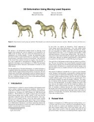
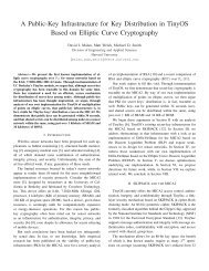
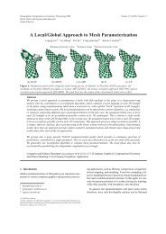
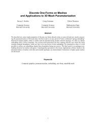
Briceño et al / <strong>Geometry</strong> <strong>Videos</strong>of the original surface by simply subsampling it – by subsamplingthe geometry image. This is commonly referredas “level-of-detail” support. When we subsample (decimate)the geometry image to obtain a lower resolution version, itis possible that we might miss cut-nodes on the boundary,and there<strong>for</strong>e cracks may become visible. To avoid this, weplace cut-nodes on boundary locations that would be sampled,even if the geometry image is decimated.Figure 1: Iterative Cutting Algorithm. We start a short cut.The resulting parametrization has high distortion at the center.The worst undersampled area is near the horns. We thencut, and reparametrize. We stop when adding a new cut increasesthe average distortion or undersampling.This cut is then improved iteratively. We greedily improvethe cut and parametrize the mesh until the qualityof the resulting parametrization no longer improves the averagedistortion or quality. The quality is measured usingthe geometric-stretch metric of Sander et al. 15 , which measuresboth the change in area and shape of triangles or facesfrom the parameter space to the object space. During eachiteration, in order to improve the cut, an angle-preservingparametrization <strong>for</strong> the current cut mesh is computed usingthe method of Floater 3 . The vertex whose adjacent faceshave the highest undersampling in the domain is identified.The parametrization is computed using a circular boundary.Then, the cut is extended by the shortest path betweenthe current cut boundary and the identified vertex. Figure 1shows iterations of the cutting algorithm on a sample mesh.Boundary parametrization. Once the cut is defined, themesh is parametrized onto the 2D domain. In order to preventgeometric discontinuities across the cut, the sampleson opposite sides of the cut must have the same geometricvalue. This is achieved by parametrizing the boundary of themesh onto a square, and assigning corresponding parametriclengths to edges on opposite sides of the cut. Vertices that lieat the junction of multiple cuts are called cut-nodes. Thesewill appear more than twice on the boundary of the square.In order to guarantee that they will be sampled exactly, weplace these samples on integral grid positions on the boundary.If the <strong>Geometry</strong> Image is compressed using a lossy encoding,additional sideband in<strong>for</strong>mation is recorded. The lossyencoding will blur the boundaries and hence the cut-nodesand boundary will not match on the reconstructed mesh,causing a seam to be visible at the cut. The sideband in<strong>for</strong>mationkeeps track of the correspondence of the cut-nodes,so that after the <strong>Geometry</strong> Image is decoded, their locationcan be aligned to match (in order to prevent seam artifacts).<strong>Geometry</strong> images <strong>for</strong>m a geometric sampling of the originalsurface. We can implement lower resolution versionsInterior parametrization. After defining the parametrizationof the boundary vertices, the parametrization of the interioris computed so as to minimize the geometric-stretchmetric of Sander et al. 15 . This metric penalizes undersamplingin the parametric domain and yields a parametrizationwith samples uni<strong>for</strong>mly distributed over the mesh surface.The algorithm uses the hierarchical parametrization frameworkof Sander et al. 14 to improve quality and convergencespeed.Compression. Once the parametrization is computed, themesh is sampled onto a 2D image. In order to sample theimage, a bounding box around the mesh is computed, themesh is scaled to fit within the RGB unit cube, and the samplesare quantized to a desired number of bits. The geometryimage is then compressed using off-the-shelf image codingtechniques (e.g., 2D wavelets). When lossy compression isapplied, the corresponding boundary samples will not necessarilymatch after decoding. This is addressed by storingadditional sideband in<strong>for</strong>mation about the topology of theboundary.Limitations. There are many advantages of being able toparametrize the surface onto one chart. It arranges the data ina compressible manner. It can be easily manipulated and parallelized.Un<strong>for</strong>tunately, many topologically and geometricallycomplex surfaces cannot be parametrized onto a squarewith low distortion.Moreover, we are mapping the surface to a square; this init by itself introduces distortion at the corners. Being of afixed aspect ratio also imposes a limitation on the unwrappingof the surface. Figure 2 shows the parametrization of asnake. Due to the “aspect-ratio” of the snake body, there ishigh distortion at the boundaries. This becomes a problem<strong>for</strong> textures, as these areas might not be rendered well. Itis possible to alleviate the problem by smoothing the pointsaway from the boundary. This is sensible in a static context.In a dynamic context the answer is not so clear, as we wouldneed to calculate the effect of this smoothing on all frames.There are many approaches to this problem, among themchartification and allowing the boundaries to be free. Wemaintain this parametrization due to its advantages in compressibilityand ease of processing. For now, we acknowledgethat <strong>Geometry</strong> <strong>Videos</strong> may not be <strong>for</strong> all objects. Withthis in mind, let us delve into the encoding of animatedmeshes.c○ The Eurographics Association 2003.
Briceño et al / <strong>Geometry</strong> <strong>Videos</strong>Figure 2: Limitations: one of the drawbacks of using a singleparametrization is that regions of high-distortion mightbe unavoidable.a single frame. Our algorithm assumes all meshes in the animationhave the same connectivity. This presents a problemif the input mesh changes connectivity or topology. The firstchallenge is not an inherent problem of geometry images.We could apply a re-meshing algorithm (e.g. 13 ) to all theframes to generate frames of equal connectivity as a preprocess.The second challenge is more difficult. Changes intopology <strong>for</strong>ce changes in the cuts which make re-using oradapting another parametrization next to impossible. Thisis a current limitation of the system. Our current solutionwould involve approaching this problem as a scene change,where a new parametrization would be used. We would needensure a smooth transition between frames with differentparametrizations. <strong>3D</strong> morphing techniques could be used <strong>for</strong>this purpose.4. Our ApproachIn this section, we describe how we extend each of the threesteps of the geometry image construction (cut, parametrization,and compression) in order to generate geometry videosfrom animated input meshes.The straight<strong>for</strong>ward way to implement <strong>3D</strong> animation encodingwith geometry images, is to apply the algorithm staticallyto each frame. The disadvantages of this approach aremany. Notice that the geometry image parametrization <strong>for</strong>msan implicit texture map. Hence if we encode each frame witha separate parametrization, we would need to update the texturemap <strong>for</strong> each frame. The same applies <strong>for</strong> any other attributein<strong>for</strong>mation that is fixed through time. Furthermore,since we are resampling the input mesh, it is unlikely thatthe two meshes will be sampled in the same way, there<strong>for</strong>e,on low-motion scenes, a jittering effect will be seen. Lastly,using different parametrizations makes it difficult to exploitthe temporal coherence that exists between frames. Differentparametrization yields complex correspondence relationshipbetween samples in different geometry images.We seek to find a common parametrization <strong>for</strong> allthe frames in the animation sequence. Using a singleparametrization yields better results because the compressionalgorithm can exploit the frame-to-frame coherence thatis present with a single parametrization; the loss due to usinga “non-optimal” parametrization in general is very small.By using a fixed parametrization <strong>for</strong> all frames one can thenstore fixed per-vertex attributes (e.g., texture, material id,etc) in a single separate image. Notice that by fixing theparametrization, we are also fixing the cut, since the cut defineshow the boundary will be mapped, and changing theboundary mapping would change the parametrization.Picking a single cut and parametrization <strong>for</strong> all frames inthe sequence does not work well if the features of the modelchange drastically from frame-to-frame (i.e., a human morphinginto a two-legged animal).Currently our parametrization is fixed and computed from4.1. CuttingWe now describe the cut algorithm that converts the meshinto one that is topologically equivalent to a disk. As describedabove, we seek to construct a single parametrization<strong>for</strong> the entire animation sequence, the cut in all of the meshesmust be equivalent (connectivity-wise).Initially, our approach used the cut found in a singleframe and applied it to all frames. We found that frames thatshowed all the important features of the object (i.e., a humanin anatomical position, or a standing cow) worked best, butonly slightly better than the worse chosen frame. That is becausecuts reach out to regions of high distortion releasingthe “tension” that exists in that area. All these areas wereusually reached when the cutting algorithm was applied toany frame.The drawback of this approach, besides being heuristic,is that it will miss areas of high-distortion if these occur atdifferent times. Figure 11, shows an example where this canhappen, where the eyes and the tail are regions of high distortion,but they occur exclusively in different frames. Thisapproach also biases regions that have an average of highdistortion, such as joints.In order to “catch” these potential areas, we seek a globalcutting algorithm. This cutting algorithm works by applyingthe single-frame cutting algorithm simultaneously to allframes. Recall that the single-frame cutting algorithm worksiteratively by cutting, computing the Floater parametrizationon the resulting mesh, finding the vertex next to the face ofhighest distortion and then making the shortest cut from thatvertex to the current boundary. The algorithm stops whenadditional cuts do not improve the average distortion. Theproblem then becomes how to find the face of highest distortionand how to compute the “shortest-path” to the boundarywhen considering all the frames.In the single frame case, the vertex of highest distortionis located by computing the geometric-stretch <strong>for</strong> each face.The vertex next to the face with the highest stretch in thenc○ The Eurographics Association 2003.
Briceño et al / <strong>Geometry</strong> <strong>Videos</strong>selected. The geometric-stretch measures how circles in theparameter space are mapped into the object space. The distortionis measured by the magnitude of the major-axis ofthe resulting ellipsis.For the global case, we have to compare or average themaximum stretch on many frames. We also do not want asingle frame with very distorted faces to dominate or drivethe algorithm astray. There<strong>for</strong>e, <strong>for</strong> each frame, we normalizethe stretch by the maximum stretch on that frame. Then,the final stretch of each face is the average of the normalizedstretch of that face in all frames.We compute the shortest distance to the boundary byusing Dijkstra’s algorithm using a proxy mesh. This nonrealizablemesh has the same connectivity of our animation,but the length of its edges is the average length of that sameedge <strong>for</strong> all frames of the animation. This method yieldedgood results.The single-frame algorithm stops when adding a cutwould increase the average distortion. This is the averagedistortion across of faces of all frames. The average distortionof a face is measured using the geometric-stretch metric.This measurement is normalized by the surface area in objectspace <strong>for</strong> each frame. It is comparable between frames,hence our criteria <strong>for</strong> stopping the algorithm considers theaverage of the average distortion across all frames withoutany modifications.The global cut does not consistently do better than choosinga cut and parametrization from a single frame either byhand or by brute <strong>for</strong>ce. The advantage is that is does consistentlywell; this reduces human-intervention or computationtime. Additionally, it can identify and relax regions of highdistortionthat do not occur in the same frame.4.2. ParametrizationGiven the global cut, we wish to find a parametrization thatminimizes the errors across all frames. We have additionalrequirements which also constrain the parametrization.In order to support level-of-detail, we would like aparametrization that uni<strong>for</strong>mly samples the surface. This allowsus to simply decimate in both dimensions each frame ofthe geometry video, to obtain a low resolution version of theanimation. If this feature is not a requirement of the application,then it is possible to tweak the points in the parameterspace to align better with features in the object space (likesharp creases). Additionally, having a uni<strong>for</strong>m parametrizationworks well <strong>for</strong> frames that may not have been taken intoaccount in building the cut and parametrization. Without apriori in<strong>for</strong>mation, uni<strong>for</strong>m sampling is likely to sample arbitraryareas better than a specialized sampling based on anotherframe.The algorithm already used by Gu et al. 4 , minimizesthe geometric stretch metric in order to parametrize themesh. This metric distributes the samples uni<strong>for</strong>mly over thesurface and minimizes the reconstruction error assuming apiecewise constant signal. Ideally we would like to modifyit to take all frames into account, or determine a referenceframe in our animation to be used <strong>for</strong> the parametrization ofthe animation.We have experimented with an approach that parametrizesthe cut mesh while considering the geometry of all frames.For an animated mesh sequence, instead of a single <strong>3D</strong> geometrychannel, we have N <strong>3D</strong> geometry channels, whereN is the number of frames. This yields a 3N-dimensionalsignal. We seek to find a parametrization that minimizes thestretch over this 3N-dimensional space, thus minimizing reconstructionerror over all frames in the sequence. But ourresults in terms of reconstruction error (after compression)were slightly worse than using the parametrization from asingle frame. In terms of worst-case distortion, this algorithmdid significantly better than the parametrization usinga single frame. We have not done enough experiments to reliablyuse this global parametrization. This is a direction <strong>for</strong>future work.Currently we have found that using an arbitrary frame(i.e., the first frame) of the animation as the reference frame<strong>for</strong> the parametrization algorithm to yield good results. Formedium de<strong>for</strong>mation animations, we have found that the cuthas a large effect on the parametrization. It already definesthe boundary, and in a sense, it has spread the regions of highdistortion around the unit square. So even choosing an arbitraryframe in our animation, yields similar results. Figure 5shows some data to support our theory.4.3. Sampling and RenderingOnce we have a cut and parametrization, we can uni<strong>for</strong>mlyconvert each frame of the animation into a geometry image.The collection of geometry images is called a geometryvideo. The conversion works by sampling over a gridthe original vertex values mapped onto the parametrization.By using the same parametrization, the samples in the samecoordinates in different frames will correspond to the samelocation on the original surface.The mesh resulting from the geometry image will haveregular connectivity. It will look like a grid. We triangulate ituni<strong>for</strong>mly along one chosen diagonal. We do not change theoriginal diagonalization once fixed, because doing so wouldyield popping or jittering artifacts in the encoded animationwhen the diagonalization changes.4.4. CompressionThe cut and parametrization allows us to generate a sequenceof geometry images. The next logical step is to compressthese images taking advantage of the coherence or redundancythat exists within each image and between each pairof frames in the sequence.c○ The Eurographics Association 2003.
Briceño et al / <strong>Geometry</strong> <strong>Videos</strong>vertices, a motion captured dance sequence (skinning) with7061 vertices, and a curling snake sequence (motion) with9179 vertices. We have also applied our algorithm to shortsequences with meshes with 38K vertices.5.1. Comparison to Static Approaches<strong>Geometry</strong> images are competitive with other static meshcompression approaches. Figure 3 shows rate-distortioncurves <strong>for</strong> a few models. Static compression methods basedon quantized deltas usually cannot support very low bitrates.Also, note that the geometry image algorithm worksbetter with a larger number of vertices. With more vertices,we have a larger bit-budget to encode the object; in bothcases we are encoding the same object.L2 distance (% of frame 1 box diagonal diagonal)6.5 x 10⁻⁴ L2 Error of Dance Sequence (8bpv)Vary Cut and ParametrizationFixed Global Cut/Parametrization from Frame 165.554.543.530 50 100 150 200 250Frame Number5.2. Cuts/ParametrizationIn order to obtain more temporal coherence and have oneuni<strong>for</strong>m parametrization <strong>for</strong> the entire animation, we wouldlike to use only one cut and parametrization. Two experimentsshow the effect of this choice.The first experiment shows that using one global cut doesnot yield much worse reconstruction. Figure 4 compares usingan “optimal” cut and parametrization <strong>for</strong> each frameversus having one fixed cut and parametrization (using thefirst frame of the sequence). Notice that the fixed global cutdoes only slightly worse in the Dance sequence and achievesabout the same quality in the Snake sequence.The second experiment shows that once a cut is defined,picking an arbitrary parametrization is not harmful.The reasoning is that the cut already relieves tensionin areas of high distortion and fixes the boundary of theparametrization. Hence, picking a different reference frame<strong>for</strong> the parametrization only changes the internal configurationslightly. Figure 5 shows the effect of fixing the cut andcalculating the error <strong>for</strong> all frames of the sequence using differentreference frames <strong>for</strong> the parametrization. The modelon frame 15 is a highly distorted cow, but even using this asthe reference frame <strong>for</strong> the parametrization, does not yield anotably higher errors <strong>for</strong> the sequence.5.3. Level of DetailLevel of detail is naturally supported by geometry imagesand hence by geometry videos. It is simple to construct acoarse version of the mesh by simply decimating (removingevery other pixel in each direction) the geometry image.It is important to have a uni<strong>for</strong>m parametrization such thatwhen decimation occurs, the texture map of the fine geometryimage also <strong>for</strong>ms a good mapping on the coarse geometryimage. In figure 10 we show the same geometry imageat two resolutions; we can combine them to present a multiresolutionversion of the mesh.The concept of temporal scalability is the same as inL2 distance (% of frame 1 box diagonal diagonal)2.2 x 10⁻⁴ L2 Error of Snake Sequence (8bpv)Vary Cut and ParametrizationFixed Global Cut/Parametrization from Frame 12.121.91.81.71.61.51.40 20 40 60 80 100 120 140Frame NumberFigure 4: Dance (7061 vertices) and Snake (9179 vertices)sequences encoded at 8 bits per vertex. We do not lose muchby using a fixed cut and parametrization.video. B-Frames can be interleaved such that if the userwants to fast <strong>for</strong>ward through an animation, the decoder doesnot have to decode all the frames. On the downside, insertedB-Frames makes the prediction <strong>for</strong> P-Frames harder sincethese are farther apart. Figure 6 shows the reconstruction errorbetween using only I-Frames, using P-Frames, or usinga combination of P-Frames and B-Frames. Notice that theuse of B-Frames increases the variance of the error, and onlyincreases the average error average slightly. B-Frames arepredicted using reference frames that are farther apart, henceare not as good predictors. The variance could be mitigatedby adaptive adjusting the frame size. Most video techniquesapplicable to MPEG are applicable here.c○ The Eurographics Association 2003.
Briceño et al / <strong>Geometry</strong> <strong>Videos</strong>Rate Distortion: Coarse Cow, Frame 1 (2904 vertices)Rate Distortion: Dance, Frame 1 (7061 vertices)Rate Distortion: Snake, Frame 1 (9179 vertices)Rate Distortion: Turtle (19124 vertices)L2 distance (% of bounding box diagonal)7654321<strong>Geometry</strong> Image (256x256) 1,2,4,8,10 bpvTouma/Gotsman (8,9,10,11,12 bit quantization)Spectral Compression(14 bits quantization, 5%,10%,20%,50% nbasis)L2 distance (% of bounding box diagonal)32.521.510.5<strong>Geometry</strong> Image (256x256) 1,2,4,8,10 bpvTouma/Gotsman (8,9,10,11,12 bit quantization)Spectral Compression(14 bits quantization, 5%,10%,20%,50% nbasis)L2 distance (% of bounding box diagonal)1.81.61.41.210.80.60.40.2<strong>Geometry</strong> Image (256x256) 1,2,4,8,10 bpvTouma/Gotsman (8,9,10,11,12 bit quantization)Spectral Compression(14 bits quantization, 5%,10%,20%,50% nbasis)L2 distance (% of bounding box diagonal)1.210.80.60.40.2<strong>Geometry</strong> Image (256x256) 1,2,4,8,10 bpvTouma/Gotsman (8,9,10,11,12 bit quantization)Spectral Compression(14 bits quantization, 5%,10%,20%,50% nbasis)8 x 10³ Bits per Vertex00 5 10 15 20 253.5 x 10³ Bits per Vertex00 5 10 152 x 103 Bits per Vertex00 2 4 6 8 10 121.4 x 10³ Bits per Vertex00 5 10 15 20 25(a) (b) (c) (d)Figure 3: Rate Distortion Curves: comparing <strong>Geometry</strong> Images to Touma/Gostman (TG) encoder, and Spectral CompressionPSNR. same cut different parametrizationsTemporal Scalability using B−Frames (Cow Sequence)Parametrizationtake from frame:13579111315S1S2S3S4S5S6S7S8S9S10S11S12S13S14S15Frame encoded706968676665 PSNR (dB)6463626160L2 distance (% of frame 1 bounding box diagonal)1.41.210.80.61.6 x 10−3 Frame NumberAll I−Frames 8bpv, fixed cut/paramAll P−Frames 8bpv, fixed cut/paramPB−Frames 8bpv (3Ps 4Bs), fixed cut/paramFigure 5: The cut has a significant effect on the parametrization.This figure shows the Signal to Noise Ratio of thereconstructed key frames of the cow sequence (2904 vertices)encoded at 8bpv. All of them use the same cut. Theparametrization is based on different frames. Notice that theerror <strong>for</strong> each frame is about the same <strong>for</strong> all parametrizations.0.40 10 20 30 40 50 60 70 80 90Figure 6: The use of B-frames allows the decoder to skipthem if necessary. One simple way to implement temporalscalability is by introducing B-Frames. The animation canbe played at half the frame rate just by dropping the B-Frames.5.4. Compression Results<strong>Geometry</strong> <strong>Videos</strong> do a good job in compressing our sampledata sets. We compare our results with a straight<strong>for</strong>ward implementationof Alexa and Müller’s 1 “Representing <strong>Animations</strong>by Principal Component Analysis.” We find waveletsare very powerful at compressing both the original geometriesand the residuals. The intuition is that by re-samplingand re-ordering the vertices, we can extract more spatial coherence.It is possible to calculate this on an irregular mesh,but handling these irregularities can be cumbersome and unpredictable.Figure 8 shows a comparison between Principal ComponentAnalysis (PCA) and <strong>Geometry</strong> <strong>Videos</strong>. Figure 8.bshows that the detail of the single frames with PCA isslightly better (see face), as it does not suffer from some ofthe smoothing of face that occurs with geometry images. Un-<strong>for</strong>tunately, PCA shows major distortion on some frames ofthe animation. PCA has worse in reconstruction error, alsobecause without enough basis, it can’t capture the exact motionof the object.Next, we consider how well the predictive encodingworks. We find that using P-Frames reduces the reconstructionerror by half <strong>for</strong> the same bit-rate using I-Frames only.P-Frames are encoded at 30% the size of the I-Frames; theoverall size is the same. Figure 7 shows the encoding ofthe Dance sequence. We note that using predictions on a 4bits per vertex encoding achieves almost the same result asapplying a new cut and parametrization to encode framesat 8 bits per vertex. This shows that by fixing the cut andparametrization we can reduce the temporal redundancy betweenframes.Finally, we are exploring partitioning the geometry imageinto regions and applying separate trans<strong>for</strong>mations to eachc○ The Eurographics Association 2003.
Briceño et al / <strong>Geometry</strong> <strong>Videos</strong>L2 distance (% of frame 1 bounding box diagonal)987654<strong>3D</strong>ance Sequence at various bitrates10 x 10−4 Frame NumberAll I−Frames 8bpv, vary cut/paramAll I−Frames 8bpv, fixed cut/paramAll P−Frames 8bpv, fixed cut/paramAll P−Frames 4bpv, fixed cut/paramAll P−Frames 2bpv, fixed cut/paramModel/SequenceCow Sequence# Vertices 2904Find Cut ‡147secs (2m27s)Find Global Cut (100 frames) ‡ 12720secs (3h32m)Parametrize (1 frame) †125secsEncode Seq. 256 × 256 8bpv † 3.03 fps(I-Frame only, given cut/param)Encode Seq. 64 × 64 8bpv †16.02 fps(I-Frame only, given cut/param)Frame Size2904 bytesDecode Stream 256x256 8bpv † 10.57 fpsDecode Stream 128x128 8bpv † 32.99 fpsDecode Stream 64x64 8bpv † 64.03 fps20 50 100 150 200Figure 7: Dance sequence (7061 vertices) encoded: at 8 bitsper vertex (bpv) using a customized cut and parametrizationper frame (vary); at 8 bpv using <strong>Geometry</strong> Images using onlyI-Frames; and at 8,4 and 2 bpv using P-Frames (0.3 size ratiobetween P-Frames and I-Frames). Notice that the encodingusing P-frames at 4 bpv is better to using only I-framesat 8bpv.region. The idea is to capture local changes better. We are inspiredby motion compensation in MPEG. Our preliminaryresults are encouraging. We find that local trans<strong>for</strong>mations<strong>for</strong>m a better predictors than using one global trans<strong>for</strong>mation.One has to be careful to blend the different trans<strong>for</strong>medregions. Without a smooth transition between trans<strong>for</strong>medregions, this predictor will yield residuals containing highfrequencies at the region boundaries which will hurt compression.5.5. TimingsIn this section we briefly report on the per<strong>for</strong>mance of oursystem. Table 1 reports the per<strong>for</strong>mance of different algorithms.The encoder was developed in Matlab 6.5 <strong>for</strong> ease ofprototyping. It has not yet been ported it to C++. The firstfive measurements concern the encoder, in particular theparametrization pre-process. Once a cut has been chosenand a parametrization computed, we can encode <strong>3D</strong> animationsat a rate of few frames per second <strong>for</strong> an image sizeof 256 × 256, and much faster with an smaller image size.The encoding time is dominated by two factors: the waveletencoding of the geometry images and the cutting and samplingof the frames in the <strong>3D</strong> animation. For example, theencoder will encode 100 frames of the Cow Sequence withan image size of 64 × 64 in 6.24 seconds: 1.69 seconds arespent cutting the meshes of each frame and preparing themto be sampled, 1.90 seconds are spent sampling the inputTable 1: <strong>Geometry</strong> Video subsystems timingsmeshes; and finally 1.66 seconds will be spent encoding theresulting <strong>Geometry</strong> Images <strong>for</strong> each frame. The wavelet encoder/decoderis a research prototype 12 and its per<strong>for</strong>mancecan be improved. For example, the wavelet basis is not hardcodedand it does not take advantage of multimedia extensionsin the hardware processor. The cutting algorithm is implementedin Matlab; The sampling (rasterization) is done insoftware without any optimizations and without taking advantageof hardware support.We can decode <strong>Geometry</strong> <strong>Videos</strong> at interactive rates <strong>for</strong>small image sizes (64). The decoding speed is dominatedby the wavelet decoder. The larger the image size, the morecomputation the wavelet decoder requires. The beauty of <strong>Geometry</strong><strong>Videos</strong> is that the per<strong>for</strong>mance <strong>for</strong> a <strong>Geometry</strong> Videoof size 64 × 64 and will be the same (assuming same filesize) regardless of the actual original mesh it represents.6. Summary and Future WorkWe introduced a new animated mesh representation, calledthe geometry video. We described an algorithm to creategeometry videos from animated meshes. Our algorithm isbased on the geometry image construction algorithm fromGu et al. 4 . We extend the algorithm to take advantage offrame-to-frame coherence during compression. We approachthis by building a global cut that takes all frames into account.We choose the reference frame <strong>for</strong> the parametrizationarbitrarily, but show, at least <strong>for</strong> our data sets, that thecut has a significant effect on the parametrization and anychoice of frame would be satisfactory.We also develop intuition <strong>for</strong> the effectiveness of waveletsin representing the geometry and residuals. The main insightis that by reorganizing and resampling the vertices of a mesh,† Windows XP, Pentium 4 at 3.06 GHz, 533MHz front side bus‡ Linux, Pentium 4 at 2.4 GHz, 533MHz front side busc○ The Eurographics Association 2003.
Briceño et al / <strong>Geometry</strong> <strong>Videos</strong>we can more easily “see” around the vertex to extract theexisting spatial redundancy. We can see in two locally independentdirections. This allows the wavelets to compressboth geometry and residual in<strong>for</strong>mation well.The key advantage of this approach is to leverage all ofthe accumulated knowledge on 2D Video encoding to allow<strong>3D</strong> animation to become another natural media. For certainclasses of animation this should be possible; <strong>for</strong> others westill have to address some of the shortcomings of using a singlesquare parametrization. It is also clear that more sophisticatedtrans<strong>for</strong>mations should help in building better predictors.The fact that we also have one continuous surfaceshould make it efficient to select or cluster regions of similarmotion together. The possibilities are many, and the advantagesunique. We hope to have shown the promise of thisapproach, and at the very least that it is viable <strong>for</strong> a subset ofanimations.AcknowledgementsWe would like to thanks Matthias Müller (ETH Zürich) <strong>for</strong>providing us with the Snake and Cow animation sequences,and Daniel Vlasic (LCS/MIT) <strong>for</strong> the Dance sequence.References1. Marc Alexa and Wolfgang Müller. Representing animationsby principal components. Computer GraphicsForum, 19(3):411–418, 2000.2. Matthias Eck, Tony DeRose, Tom Duchamp, HuguesHoppe, Michael Lounsbery, and Werner Stuetzle. Multiresolutionanalysis of arbitrary meshes. ComputerGraphics, 29(Annual Conference Series):173–182, 1995.3. Michael S. Floater. Parametrization and smooth approximationof surface triangulations. Computer AidedGeometric Design, 14(4):231–250, 1997.4. Xianfeng Gu, Steven J. Gortler, and Hugues Hoppe.<strong>Geometry</strong> images. In Proceedings of the 29th annualconference on Computer graphics and interactive techniques,pages 355–361. ACM Press, 2002.5. Igor Guskov, Kiril Vidimce, Wim Sweldens, and PeterSchröder. Normal meshes. In Kurt Akeley, editor,Siggraph 2000, Computer Graphics Proceedings,pages 95–102. ACM Press / ACM SIGGRAPH / AddisonWesley Longman, 2000.6. Zach Karni and Craig Gotsman. Spectral compressionof mesh geometry. Computer Graphics (SIGGRAPH2000), pages 279–286, 2000.7. Andrei Khodakovsky, Peter Schroder, and WimSweldens. Progressive geometry compression. ComputerGraphics (SIGGRAPH 2000), 2000.8. Aaron Lee, Henry Moreton, and Hugues Hoppe. Displacedsubdivision surfaces. In Kurt Akeley, editor, Siggraph2000, Computer Graphics Proceedings, pages85–94. ACM Press / ACM SIGGRAPH / Addison WesleyLongman, 2000.9. Aaron W. F. Lee, Wim Sweldens, Peter Schröder,Lawrence Cowsar, and David Dobkin. MAPS:Multiresolution adaptive parameterization of surfaces.Computer Graphics, 32(Annual ConferenceSeries):95–104, 1998.10. Jerome Edward Lengyel. Compression of timedependentgeometry. In Proceedings of the 1999 symposiumon Interactive <strong>3D</strong> graphics, pages 89–95. ACMPress, 1999.11. Wojciech Matusik, Chris Buehler, Ramesh Raskar,Steven J. Gortler, and Leonard McMillan. Image-basedvisual hulls. In Proceedings of the 27th annual conferenceon Computer graphics and interactive techniques,pages 369–374. ACM Press/Addison-Wesley PublishingCo., 2000.12. Ng Mow-Song. An implementation of EZW.http://pesona.mmu.edu.my/˜msng/EZW.html, September2002.13. Emil Praun, Wim Sweldens, and Peter Schröder. Consistentmesh parameterizations. In Proceedings of the28th annual conference on Computer graphics andinteractive techniques, pages 179–184. ACM Press,2001.14. Pedro V. Sander, Steven J. Gortler, John Snyder, andHugues Hoppe. Signal-specialized parametrization.Eurographics Workshop on Rendering, 2002.15. Pedro V. Sander, John Snyder, Steven J. Gortler, andHugues Hoppe. Texture mapping progressive meshes.In Eugene Fiume, editor, SIGGRAPH 2001, ComputerGraphics Proceedings, pages 409–416. ACM Press /ACM SIGGRAPH, 2001.16. Ariel Shamir, Chandrajit Bajaj, and Valerio Pascucci.Multi-resolution dynamic meshes with arbitrary de<strong>for</strong>mations.In Proceedings of the conference on Visualization2000, pages 423–430. IEEE Computer SocietyPress, 2000.17. Ariel Shamir and Valerio Pascucci. Temporal and spatiallevel of details <strong>for</strong> dynamic meshes. In Proceedingsof the ACM symposium on Virtual reality software andtechnology, pages 77–84. ACM Press, 2001.18. Gabriel Taubin and Jarek Rossignac. Geometric compressionthrough topological surgery. ACM Transactionson Graphics, 17(2):84–115, 4 1998.c○ The Eurographics Association 2003.
Briceño et al / <strong>Geometry</strong> <strong>Videos</strong>L2 distance (% of frame 1 bounding box diagonal)0.0350.030.0250.020.0150.010.005"dance0" Sequence <strong>Geometry</strong> Images vs PCAPCA with 16 basisPCA with 32 basis<strong>Geometry</strong> Image at 2bpv<strong>Geometry</strong> Image at 8bpv00 50 100 150 200Frame Number<strong>Geometry</strong> Image(2bpv)(a)OriginalPCA(32 basis)(a)(b) (c) (d)Figure 9: Pipeline. (a) We start with a cut of the input mesh.(b) the edges of the cut will map to the boundary edges ofthe parametrization. (c) we raster-scan the parametrizationand interpolate the points. (d) We compress, decompress andresample the mesh. The cut or seam will open if the decodingis lossy. (e) We use the boundary in<strong>for</strong>mation to close seams.(e)Decimate (4x)(a)(b)(c)Frame 146(b)Figure 8: PCA and <strong>Geometry</strong> Images Comparison: We compareAlexa and Müller’s “Representing <strong>Animations</strong> by PrincipalComponents” 1 method to <strong>Geometry</strong> Images. (a) ThePCA encoded animation with 16 basis (no compression perbasis) on 180 frames corresponds to roughly an encoding at8bpv, which per<strong>for</strong>ms <strong>for</strong> most frames comparable to <strong>Geometry</strong>Images at 2bpv. (b) Objects on the bottom show the reconstructionusing <strong>Geometry</strong> Images, the original mesh, andthe reconstruction using PCA. The reconstructed meshes arecolor-coded to show the relative magnitudes of the errorfrom the original mesh. Note the scaling distortion in thePCA reconstruction.Figure 10: Level-of-Detail: by decimating the geometry image(a) we obtain a lower resolution version (b); We cancombine the two to support a multi-resolution version of themesh (c); care must be taken at the transition edges, this is asimple operation due to the regularity of the mesh.(a) (b) (c)Figure 11: Global Cut. (a) Shows the cuts of turtle with itstail sticking out. (b) Shows the cuts of turtle now with its eyessticking out but tail retracted; tail now does not have muchdistortion. (c) Shows a base turtle with the global cuts builtfrom (a) and (b)c○ The Eurographics Association 2003.