Manual - model IndAC (pdf) - Biddle.info
Manual - model IndAC (pdf) - Biddle.info
Manual - model IndAC (pdf) - Biddle.info
- No tags were found...

You also want an ePaper? Increase the reach of your titles
YUMPU automatically turns print PDFs into web optimized ePapers that Google loves.
Are These theOnly Programsfor Treatmentof Reading andLanguageProblems?This matrix of widelyused programs doesnot include all ofthe programs that havebeen proven effectivein remediating readingdisabilities or preventingreading problemsin “at risk”children. Research onearly intervention andprevention of reading disabilities has been conductedwith many other instructional materials and programsthat are not included in the matrix (see references).Additional reviews of instructional and interventionprograms can be found on the website of the FloridaCenter for Reading Research (www.fcrr.org).Are These Programs Research-Basedor Evidence-Based?What Program CharacteristicsAre Most Important?Intervention and remediation researchers report overand over that the most effective programs ofinstruction, at all ages, explicitly address multiplecomponents of oral and written language learningin an integrated manner. These components include:phonological awareness; vocabulary development;reading comprehension skills and strategies;beginning and advanced decoding skills, with spellingincluded; reading fluency; handwriting; grammar;written composition; and strategies for learning.Certain programs that have been validated by researchtarget some of these components, but the strongestcontain lesson formats in which these components areinterrelated and taught in parallel strands. In additionto teaching the content strands, effective approachesare explicit, systematic, multisensory, and cumulative.Interested consumers should contact programwebsites or program offices for specific<strong>info</strong>rmation on research supporting the approach,and for other key <strong>info</strong>rmation. Many of theseprograms provide websites, videos or DVDsexplaining their unique characteristics.The best studies of program effectiveness reportthe characteristics of the students in the study, theduration and intensity of the intervention, the trainingand skill of the teachers, the fidelity of programimplementation, and the exact methods that wereused. They also measure student outcomes multipletimes during intervention with several valid, acceptedassessments. Such research is expensive and complex,and many effective, clinically tested programs existthat have not been included in rigorous comparisonstudies. Some programs in the matrix are in thatcategory. Other programs, not on the matrix, havebeen proven effective for teaching specific skills tocertain kinds of children at particular stages of readingdevelopment, but do not identify themselves as MSLprograms. Each program will provide the existingevidence for effectiveness on request. In summary, theeffectiveness of some of the programs on the matrixis established by scientific standards, and theeffectiveness of others is established through clinicaluse over time. The matrix does not include allprograms with demonstrated effectiveness.
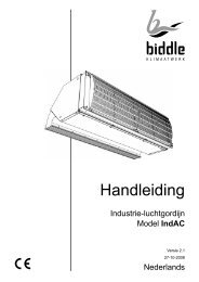
Industrial Air Curtain1.3 About the unit1.3.1 ApplicationsThe air curtain <strong>model</strong> <strong>IndAC</strong> is designed toseparate the indoor and outdoor climates orthe climates in two rooms. It is installedabove or next to the door, across the fullwidth or length of the doorway. The <strong>IndAC</strong><strong>model</strong> is particularly suitable for larger doorsin industrial buildings.Depending on the type, the air curtain iseither hung horizontally above the doorwayor installed vertically next to the doorway (tothe left or right or on both sides).1.3.2 Principle of operation1 IntroductionThe air curtain draws air from the room andblows it, either heated or not, as a directionalair stream across the doorway.The air curtain reduces the undesired effectsof an open door by either reducing the exchangeof air between two rooms or heatingthe entering air, or by combining these twofeatures.1.3.3 Type designation, unitThe type designations, when combined,constitute the type code for the relevant unit,for instance:<strong>IndAC</strong> S-150-W1-0<strong>IndAC</strong> M-200-E-1L<strong>IndAC</strong> L-225-A-2RVarious combinations can be made.Explanation of type code of unitSeries <strong>IndAC</strong> Industrial AirCurtainRangeS, M, L, XLUnit Size 150, 200, 225 air dischargelength (in cm)Example of a horizontal installationHeatingW1, W2, W3 hot waterEelectricInstallationPositionA01L, 1R2L, 2Rwithout heating(Ambient)See section1.3.4.Example of a vertical installationVersion 2.1, English (27-10-2008) 5
B1.3.4 Installation positionscCaution:The unit has been specifically designed forthe installation position indicated in the typecode. The unit cannot be used in a differentposition.0 horizontal,above door1.3.5 Type plateYou will find the type plate on the heatingsection of the unit.Type <strong>IndAC</strong> M-200-W2<strong>Biddle</strong> bvCode U 400 V 3N~ 50 HzMarkowei 4NL-9288 HA Kootstertille Nº 123456/1-1 06-36 Imax L1 2,1 AExample of a type plateImax L22,1 AM 133 kg Imax L3 2,1 AMedium LPHW Pmotor 1,08 kWpmax 800 kPa Pheating -References on the type plateTypefull type code of unitMweight of unit1Lvertical, left ofdoor, square towallP maxUI maxmaximum permissible operatingpressure (for units with water heating)supply voltagemaximum current strengthP motormaximum input power for fansP heatingmaximum input power for heating(with electrically heated units)1Rvertical, right ofdoor, square towall1.4 Required parts2Lvertical, left ofdoor, parallel towall1.4.1 Supplied partsWith each installation:- cable to connect units to each otherWith horizontal installation:2Rvertical, right ofdoor, parallel towall- suspension rails (2 per unit, also used forfixing the unit to the pallet)With vertical installation:intake and discharge direction (not to beblocked)inspection side (to be accessible)fan terminal box- coupling plates (2 per unit)- securing bracket6 <strong>Manual</strong> <strong>model</strong> <strong>IndAC</strong>
Industrial Air CurtainnNote :On delivery, some parts may have beenpackaged within the unit (behind the inspectionpanel).1.4.2 AccessoriesWith each installation:- control unit (always required)With vertical installation:- base plate (recommended)1.4.3 Parts not suppliedThe following parts required for installationshould be purchased from other suppliers:- threaded rods (metric M12)- cable to connect unit and control unit- isolating switch- fuse for control unit- door contact switch (optional)- room thermostat (optional)1.5.2 Installation, maintenance andservicewWarning:The unit may be opened by qualifiedtechnical staff only.ê çBefore opening the unit:1 Introduction- Switch the unit off with the control unit.- Wait until the fans have stopped.- Allow the unit to cool down as the heatexchanger can be very hot.- Switch the unit off at the mains.- Close CH supply (if possible).w Warning:The fins of the heat exchanger are sharp.1.5 Safety instructions1.5.1 OperationwWarning:Do not insert any objects into the intakeand discharge openings.Never block the intake and dischargeopenings.çFor units with heating: the intake side canbe hot.Version 2.1, English (27-10-2008) 7
B2 Installation2.1 Safety instructionsw Warning:Installation works may be performed byqualified technical staff only.Do not perform any connection workunless you are qualified to work with400V three-phase current.Before opening the unit, follow the safetyinstructions in section 1.5.2.2 Delivery check2.3.2 MiscellaneouscCaution:The infiltration of coarse dust, cement, etc.may damage the unit. So long as such contaminantsare in the room,- do not put the unit into operation;- cover the intake and discharge openings.The packaging, for example, can be used forthis.2.4 Suspending unitshorizontallyOnly with installation position type 0- On delivery, check the unit and its packaging.Report any transit damage immediatelyto the driver and supplier.- Make sure that all parts have been supplied(see section 1.4). Report any defectsto the supplier immediately.2.3 General instructions2.3.1 Order of working<strong>Biddle</strong> recommends following the order ofworking described in this section for performingthe installation works.n Note:Make sure you perform all operations thatare required for the installation of your unit.Check the type plate and refer to section1.3.5 if you are not sure about the <strong>model</strong> ortype of your unit.Example of a horizontal installation2.4.1 Method of suspensionThis manual assumes suspension from anauxiliary structure, consisting of two horizontalbeams positioned above the door.8 <strong>Manual</strong> <strong>model</strong> <strong>IndAC</strong>
Industrial Air Curtain2 InstallationExample of an auxiliary structureYou may also fix the units directly to theceiling, or to another horizontal structure,using the screw holes in the upper side of theunit.Make sure that the structure from which theunit is to be suspended can hold the weightof the unit.2.4.2 Positioning- Position the bottom face of the unit at thesame height as the doorway.- Position the discharge side of the unit asclosely as possible to the doorway to ensureoptimum operation.- Center the row of units in relation to thedoorway.- Units of different widths can be positionedin random order.- Make sure that the inspection and intakesides of the units remain accessible formaintenance.wWarning:Ensure that all units can freely take in andblow out air across the entire width.2.4.3 Mounting the unitsPerform the following for each unit:1 Lay the unit down in horizontal position.2 Insert threaded rods 1 (M12) into thefour screw holes in the upper side of theunit.3 Provide all threaded rods with locknuts2, and tighten these.wWarning:The threaded rods must be secured, otherwisethe unit may come down.4 Provide all threaded rods with locknuts3.5 Bring the unit into position using liftingequipment.6 Put the suspension rails 4 upon theauxiliary structure, and fasten them withnuts 5 to the threaded rods of the unit.7 Allow the unit to hang freely.Version 2.1, English (27-10-2008) 9
B2.4.4 Adjusting and securing2.5 Installing units verticallyOnly with installation position types 1and 21 Position the units against one another, inone line, by placing the suspension rails6 against one another. You may want tofix the suspension rails to one another.c Caution:Allow the units to hang independently fromeach other. Do not fix them directly to oneanother.2 Fasten the suspension rails to the auxiliarystructure.wWarning:Make sure that the suspension rails cannever come loose from the auxiliarystructure.3 Adjust the units to the same height, andlevel them by tightening the nuts 5.cCaution:Ensure that the units are level in both directions;otherwise the fans may run out of true.4 Secure the suspension to the threadedrods by tightening the locknuts 3.wWarning:The threaded rods must be secured, otherwisethe unit may come down.Example of a vertical installation2.5.1 Method of installationThis manual assumes that the unit will beplaced on a base plate (accessory). Theunits are stacked on one another.cCaution:If no base plate is used, provide for a horizontaland completely even surface, otherwisethe fans may run out of true.Whilst the units could be standing freely, it isalways necessary to secure them to the wall.2.5.2 Positioning- Depending on the type, position the unitsto the left or right side of the door. Referto section 1.3.4.cCaution:Do not install the unit in any positionother than that for which it is designed.- Position the discharge side of the unit atthe same width as the doorway.- Position the discharge side of the unit asclosely as possible to the doorway to ensureoptimum operation.10 <strong>Manual</strong> <strong>model</strong> <strong>IndAC</strong>
Industrial Air Curtain2 Installation- Units of different dimensions can bestacked in random order.- Make sure that the intake and inspectionsides of the units remain accessible formaintenance purposes.wWarning:Ensure that all units can freely take in andblow out air across the entire height.2.5.3 Installing the units2 Position the first unit on the base plate.1 Position and fix the base plate 1 to thefloor.cCaution:3 Fasten the unit to the base plate usingcoupling plates 2.cCaution:Screw the coupling plates to both sides ofthe unit.Ensure that the base plate is level.4 Position the second unit on top of thefirst one, and fasten them to one anotherusing coupling plates 3.Version 2.1, English (27-10-2008) 11
BcCaution:Screw the coupling plates to both sides ofthe unit.5 Position the third unit, if any, in the sameway.2.6 Connecting units to theCH systemOnly for units with water heating (type W)2.6.1 General2.5.4 Securing1 Fasten a securing bracket 4 to the topmostunit using one of the screw holes inthe unit.2 Fasten the securing bracket to a wall orother permanent structure.cCaution:If you place more than 3 units on top ofeach other: apply a securing bracket to each2 nd or 3 rd unit.The connections for the supply and returnpipes are indicated on the units using arrows.Valves for venting 1 and draining 2 the heatexchanger are located on the air intake side.cCaution:<strong>Biddle</strong> recommends the inclusion of a valvein each pipe.cCaution:The fans are not resistant to high temperatures.Where necessary, take measures tolimit the discharge air temperature.12 <strong>Manual</strong> <strong>model</strong> <strong>IndAC</strong>
Industrial Air Curtain2 InstallationCritical discharge air temperatures and watertemperature ranges (with 400V/50Hz only)- The mains power supply to the controlunit must be separately fused.unit typeS-W1M-W1S-W2M-W2S-W3M-W3L-W1XL-W1L-W3XL-W3maximumallowed dischargeairtemperaturewater temperatureranges whereexceedancemay occur65 °C above120/100 °C65 °C above90/70 °C or82/71 °C65 °C above80/60 °C65 °C above130/110 °C65 °C above90/70 °C- In emergency and maintenance situations,it must be possible to switch off theentire installation using an isolatingswitch.- All connections must be made accordingto the applicable local laws, regulationsand standards.wWarning:The units and must be earthed(grounded).2.7.2 Making connections within theunits2.6.2 Connecting water pipes1 Lay and connect the water pipes to theunits.2 Fill the CH system.3 Vent the heat exchangers.4 Check the connections for leaks.2.7 Connecting the fans2.7.1 GeneralCabling with horizontal installation position type 0(equal to vertical installation position type 1)The fans in the units are powered centrallyand controlled from the control unit. Thecontrol unit is connected to the mains powersupply.cCaution:- The power supply to the fans may bewired through between 3 units at most(with type XL: 2 units at most).Consult <strong>Biddle</strong> if you are going to connectmore than 3 units (XL: 2 units) toone control unit.Version 2.1, English (27-10-2008) 13
B- Apply a cable gland in the feedthrough5 for pull relief purposes.4 Connect the feeder cable to the terminalblocks in the terminal boxes 2 accordingto the wiring diagram.cCaution:Do not yet switch the mains supply on.2.8 Connecting the electricheatingOnly for units with electric heating(type E)Cabling with vertical installation position type 21 Remove the inspection panel 1 from thefree side of the unit.2 Remove the cover from terminal box 2.3 Lay the feeder cable between the controlunit and the terminal box in one unit ofyour choice as well as between the terminalboxes in the units.- Lead the cable through the walls ofthe units, via the holes 3 and 5.You may lead the cable inwardthrough either end of the row ofunits.- Fasten the cable to the edge 4 insidethe unit using the cable clips.wWarning:Do not allow the cable to lie orhang loosely.- Make the grommets in the terminalboxes to measure.cCaution:Ensure the grommets have suchtight fit around the cable that theyremain watertight.2.8.1 GeneralThe electric heating of each unit is separatelyconnected to the mains power supply. Theheating is controlled using the control unit.cCaution:- In emergency and maintenance situations,it must be possible to switch off theentire installation using an isolatingswitch.- All connections must be made accordingto the applicable local laws, regulationsand standards.nNote :Each unit has an isolating switch to facilitatemaintenance. This switch switches off onlythe electric heating of the relevant unit anddoes not affect the fans or the other units.wWarning:The units must be earthed (grounded).14 <strong>Manual</strong> <strong>model</strong> <strong>IndAC</strong>
Industrial Air Curtain2 Installation2.8.2 Opening the heating sectionPerform the following for each unit:1 Set the isolating switch 1 on the unit tothe zero position.2 Remove the cover 2.3 Remove the inlet grille 3.4 Remove the cover from the cable compartment4.- Lay the cable in the cable compartment4.wWarning:Do not allow the cable to lie orhang loosely.- Apply a cable gland in the feedthroughfor pull relief purposes.2 Connect the feeder cable to the isolatingswitch 5 (blue) according to the wiringdiagram. Connect the earth cable to theterminal block 6 (green and yellow).2.8.4 Connecting the control cablewithin the units2.8.3 Connecting the feeder cablewWarning:Make sure that the mains power supply isswitched off.Perform the following for each unit:1 Lay the feeder cable to the unit:- Lead the cable through either hole 1or 2 or 3. You may lead the cablethrough an adjacent unit.- Where necessary, interchange thecable entry plate at hole 2 or 3.1 Lay the control cable between the controlunit and one unit of your choice as wellas between the different units.- Lead the cable either through hole 2or 3. You may lead the cable inwardthrough either end of the row ofunits.- Lay the cable in the cable compartment4.wWarning:Do not allow the cable to lie orhang loosely.- Apply a cable gland in the feedthroughfor pull relief purposes.Version 2.1, English (27-10-2008) 15
B2 In each unit, connect the control cable tothe terminal block 7 according to thewiring diagram.2.9 FinishingFor units with electric heating:1 Place cover 4 back on the cable compartment.2 Place the inlet grilles 3 back.3 Place the cover 2 back.For all units:2.10 Switching on andchecking operationFor all units:1 Check the following connections:- power supply;- cabling between control unit andunits, and between the differentunits;- external control components (if any).2 Switch the mains supply on.3 Switch the air curtain on using the controlunit, and check if the air curtain blowsout air.cCaution:If the fans run out of true, the unit maynot be standing or hanging completelylevel. Correct this where necessary.4 Check the direction of rotation of thefans.4 Place the covers back on the terminalboxes 2 in order to protect the connectionsfrom dirt and cleaning.5 Place the inspection panels 1 back.wrong: the bladesgo forwardcorrect: the bladesgo backwardIf necessary, correct the direction of rotationby interchanging the connections oftwo phases from the mains supply.cCaution:The fans are not resistant to prolongedrotation in the wrong direction.For water-heated units:5 Check if the heat exchanger is connectedcorrectly.6 Make sure the CH system is turned on.7 Feel whether the discharged air getswarm.16 <strong>Manual</strong> <strong>model</strong> <strong>IndAC</strong>
Industrial Air Curtain2 Installation8 Vent the heat exchanger, if necessary.For units with electric heating:9 Set the isolating switches on all units toposition 1.10 Switch the air curtain on using the controlunit.11 Feel if the discharged air gets warm.Version 2.1, English (27-10-2008) 17
B3 Maintenance3.1 Safety instructionswWarning:Maintenance works may be performed byqualified technical staff only.Before opening the unit, follow the safetyinstructions in section 1.5.3.2 Access3.2.1 FansWith horizontal installation position type0, and vertical installation position type 1:1 Remove the discharge section 1: loosenbolts 2 and unhook the discharge section.2 To access the terminal box of the fans:remove inspection panel 3.3 To take out the fans: loosen bolts 4 andtake out the fan along with bracket 5.With vertical installation position type 2:1 Remove inspection panel 3.2 To take out the fans: loosen bolts 4 andtake out the fan along with bracket 5.18 <strong>Manual</strong> <strong>model</strong> <strong>IndAC</strong>
Industrial Air Curtain3 Maintenance3.2.2 Heating elementFor water-heated units:3 Remove the inlet grille 3.4 Remove the cover from the cable compartment4.3.3 CleaningYou can clean the unit's interior and exteriorwith water and a domestic cleaning agent.Do not use any solvents.The fans can be cleaned with water as well.The unit has holes for the discharge of water.wWarning:Do not spray water on the fans and terminalboxes.Carefully remove dust from the heating elementwith a vacuum cleaner.dDanger:Do not clean electrically-heated units withwater.3.4 Scheduled maintenance1 Remove inlet grille 1.For units with electric heating:1 Set the isolating switch 1 on the unit tothe zero position.2 Remove the cover 2.3.4.1 Monthly maintenance- Check the heating elements and the fansfor dust and other contaminants. Clean ifnecessary.- Check if all fans are working.- Check if the air curtain is working at allcontrol unit settings.- Check the discharge section for contaminationsand/or blockages; clean ifnecessary.For units with water heating:- Check for water leaks. If there is a leak,disconnect the unit from the mains, andrepair the leak.- Check if the water circuit contains anyentrapped air. Bleed if necessary.Version 2.1, English (27-10-2008) 19
B3.4.2 Annual maintenance- Perform all monthly checks.- Check the cabling between the terminalboxes in the units and the control unit.- Check the casing, the hanging or fixingconstruction, and the securing of eachunit.- Check if the fans are mounted correctlyand are not running out of true. If necessary,fasten them again.For units with electric heating:- Check the wiring between the control unitand the heating section.- Check the feeder cables and the connectionsin the heating section.- Check the relays in the heating section.20 <strong>Manual</strong> <strong>model</strong> <strong>IndAC</strong>
Industrial Air Curtain4 Solving problems4 Solvingproblems4.1.1 GeneralIf the air curtain does not work, or not properly,perform the checks mentioned below.If that does not help, there may be a defect.In that case, alert the installer.4.1.2 Unit does not discharge any air1 Check whether the air curtain has beenswitched on by the control unit: see thecontrol unit documentation.2 Check if the unit is not disabled by anexternal control component (door switchor room thermostat).3 Check if mains power is supplied.4 Reset the thermal protector of the fansto: see the control unit documentation.For electrically heated units:4 Check whether the isolating switch on allunits is set to position 1.5 Check if mains power is supplied to eachunit.6 Reset the high-limit thermostat: see thecontrol unit documentation7 Check the control knob 1 in the unit: itmust always be set to 60° C.4.1.3 Unit discharges little air1 Remove obstacles in front of intake anddischarge openings.2 Check the heat exchanger for contamination.Clean it if necessary.3 Check the direction of rotation of thefans: see section 2.10.4.1.4 Unit does not heat, or too little1 When facing draught: select a higher fanspeed using the operation switch.2 Does the unit blow out enough air? If not,perform the checks in sections 4.1.2 and4.1.3.For water-heated units:3 Check the operation of the CH system.Version 2.1, English (27-10-2008) 21
BBlank22 <strong>Manual</strong> <strong>model</strong> <strong>IndAC</strong>
Industrial Air CurtainBlankVersion 2.1, English (27-10-2008) 23
Declaration of ConformityManufacturer:<strong>Biddle</strong> BVAddress: Markowei 49288 HA KootstertilleTHE NETHERLANDSWe declare that the following product.Product description:Brand:Model:Type:Industrial air curtain<strong>Biddle</strong><strong>IndAC</strong><strong>IndAC</strong> S-150-W, S-200-W, M-150-W, M-200-W<strong>IndAC</strong> L-150-W, L-225-W, XL-150-W, XL-225-W<strong>IndAC</strong> S-150-E, S-200-E, M-150-E, M-200-E<strong>IndAC</strong> S-150-A, S-200-A, M-150-A, M-200-A<strong>IndAC</strong> L-150-A, L-225-A, XL-150-A, XL-225-AIn accordance with the following Directives:73/23/EEC89/336/EECthe Low Voltage Directivethe Electromagnetic Compatibility DirectiveHas been designed and manufactured to the following specifications:EN 50081-2:1993EN 50082-2:1994EMC – Generic emission standardpart 2. Industrial environments.EMC – Generic immunity standardpart 2. Industrial environments.I hereby declare that the equipment named above has been designed to comply with the relevantsections of the above referenced specifications. The unit complies with all essentials requirements ofthe directives.Signed by : P. Stoelwinder, Managing Director, 2007CE declaration <strong>IndAC</strong> standard.doc