ANALYSIS OF DISTORTION OF A THIN-WALLED ... - students.tut.fi
ANALYSIS OF DISTORTION OF A THIN-WALLED ... - students.tut.fi
ANALYSIS OF DISTORTION OF A THIN-WALLED ... - students.tut.fi
- No tags were found...

Create successful ePaper yourself
Turn your PDF publications into a flip-book with our unique Google optimized e-Paper software.
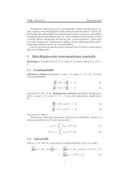
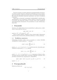
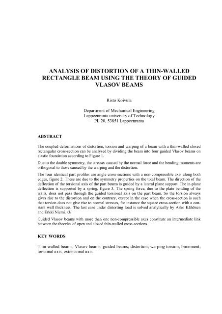
<strong>ANALYSIS</strong> <strong>OF</strong> <strong>DISTORTION</strong> <strong>OF</strong> A <strong>THIN</strong>-<strong>WALLED</strong>RECTANGLE BEAM USING THE THEORY <strong>OF</strong> GUIDEDVLASOV BEAMSRisto KoivulaDepartment of Mechanical EngineeringLappeenranta university of TechnologyPL 20, 53851 LappeenrantaABSTRACTThe coupled deformations of distortion, torsion and warping of a beam with a thin-walled closedrectangular cross-section can be analysed by dividing the beam into four guided Vlasov beams onelastic foundation according to Figure 1.Due to the double symmetry, the stresses caused by the normal force and the bending moments areorthogonal to those caused by the warping and the distortion.The four identical part pro<strong>fi</strong>les are angle cross-sections with a non-compressible axis along bothedges, <strong>fi</strong>gure 2. These are due to the symmetry properties on the total beam. The direction of thedeflection of the torsional axis of the part beams is guided by a lateral plane support. The in-planedeflection is supported by a spring, <strong>fi</strong>gure 3. The spring force, due to the plate bending of thewalls, does not pass through the guided torsional axis on the part beam. So the torsion alwaysgives rise to the distortion and on the contrary, except in the case when the cross-section is suchthat torsion does not give rise to normal stresses, for instance the square cross-section with a constantwall thickness. The last case under distorting load is solved analytically by Asko Kähönenand Erkki Niemi. /3/Guided Vlasov beams with more than one non-compressible axes consti<strong>tut</strong>e an intermediate linkbetween the theories of open and closed thin-walled cross-sections.KEY WORDSThin-walled beams; Vlasov beams; guided beams; distortion; warping torsion; bimoment;torsional axis, extensional axis
q Dq DvA P 1P 2 B P 4P 3q Dq DFigure 1. Distortion of a thin-walled rectangular cross-sectionThe mid-axes P i of the webs are non-compressible hinges. The hinged “planesupports“ BP i are rigid. The “deflection“ v of the part beam is normal to the line P 1 P 2 .Angle cross-section, guided by non-compressible axes at the edges
Our basic element is an angle cross-section, the deformation of which is restricted by anon-compressible axis, a continuous axial support at both edges. Its degrees of freedom,until further notice neglecting the shear deformation, are bending around the line P 1 P 2 , thedeflection being normal to this line, and the angle of twist around the torsional axis, thecorner axis A. The indices refer to corresponding systems of axes and special points. As tothe transformations between these systems I refer to the reference /1/.v 1 ,v 2 w,w 3~w z 3v,v 3h~v b/2 z P 1 αz 1 ,w 1 ,w 2A,O 1~ zy 01y 01 = a 2 /(a + b)/2 = S w1 /A (1)a/2 O z 2φ 0 z 01 = b 2 /(a + b)/2 = S v1 /A (2)t~ y2 2O 3 c = a + b(3)y 2 y, y 3 aβ = arctan(b/a) = arcsin(b/c)= arccos(a/c) = π/2 − α (4)βα = arcsin(a/c) = arccos(b/c)(5)P 2 h = bsinα = acosα = ab/c (6)z 01by 1Figure 2. An angle cross-section with non-compressible axes at the edgesThe displacement and force quantities like deflections v(x) and w(x), rotations θ v (x) =− w′( x) = − dw(x)/dx and θ v (x) = v´(x), bending moments and shear forces are given in aright-handed (anti-clockwise) system of axes, but the measure quantities like x, y, z and thesectorial area ω(s) in a left-handed (clockwise) system. Then some important matrices aresymmetric, and the force and displacement quantity “vectors“ {F} and {u} are in the sametime without minus signs.In <strong>fi</strong>gure 2 <strong>fi</strong>ve systems of axes and special points are shown. Each of them has the sectorialpole at point A.- AO 1 xy 1 z 1 , the axes of which coincide with the mid-lines of the webs, is a generic system,in which the cross-section integrals are easy to calculate.- AOxy 2 z 2 is a parallel to the web mid-lines centroidal system- AOx ~~ yz is the fundamental system with the origin at the centroid and axes parallel to theprincipal directions. In this case it has not much use.- AOxyz is a centric system with the axes parallel to those of the solving system. Theguided (eccentric) special points are mostly determined using this system.
- AO 3 xy 3 z 3 is the solving system, in which the effective degrees of freedom are mutuallyorthogonal and the force quantities can be computed independently from the active loads.For this cross-section the sectorial area at the wall mid-lines is zero, without lateral supports,for the arm h s (s) of a parallel to s unit vector i ( s) around the pole A is zero for all s:h s (s) ≡ 0 , ~ ω () s ≡ 0 (7)This ful<strong>fi</strong>ls at the non-compressible axes the condition ~ ω ( s ) ~1= ω ( s2 ) = 0 . For the solvingsystem AO 3 xy 3 z 3 the pole is still at the corner A and sectorial area is zero:a y3 − a y0 = 0 , a z3 − a z0 = 0 , ω 3 (s) ≡ 0 (8)The guided origin of the solving system is placed at the intersectional point O 3 of thestraight line between the non-compressible axes with the normal drawn to this line throughthe centroid. In this system the cross-sectional integrals are expressed below. The subscriptzero ( 0 ) refers to the centroidal system AOxyz, parallel to the solving system.6 5 3 3 5 6ta ( + 4ab+ 6ab + 4ab + b)I v3 = I v0 =2 212( a + b )( a+b)I w0 = ta 2 b 2( a + b )2 212( a + b )I w3 = I w0 + Ah 2 /4 = ta 2 b 2( a + b )2 2+ ta 2 b 2( a + b )2 212( a + b ) 4( a + b )s= ta 2 b 2( a + b )2 23( a + b )= ta 2 b 2( a + b )23cI vw3 = I vw0 = tab ( a 3 − b 3 )2, S w3 = − Ah/2 = − tab ( a + b ), S v3 = 0 (12),(13),(14)12c2cThe model of the quarter of the box beam as a guided Vlasov beam on elastic foundationThe functioning of the upper left corner part of the box beam of <strong>fi</strong>gure 1 with its effectivedegrees of freedom can be modelled as a guided Vlasov beam in <strong>fi</strong>gure 3. The active degreesof freedom of the cross-section are the deflection of some pole A 5 of the axis w 5 andthe angle of twist . In the reality the centre B of the box beam, in <strong>fi</strong>gure 3 the point A 4 , hasno deflections due torsion or distortion, but in the analogy with the Vlasov BEF (beam onelastic foundation) it has a motion v 4 (x) normal to the guided neutral line w 4 (P 1 P 2 ). Indirection w it is <strong>fi</strong>xed both in the model and the reality. The corner A, the concentrationaxis of the loads q D and q T , has deflections as if the part beam with rigid-in-plane crosssectionwere supported according to <strong>fi</strong>gure 3.If the shear deformation γ * (x) were neglected at the pro<strong>fi</strong>le line like usually is supposedfor the usual sectorial areaγ xs (x,s) = 0 , (15)it would not be possible for a beam of <strong>fi</strong>gure 3 to twist at all, except if the parallel to P 1 P 2plane support passed through corner A of the cross-section. That is to say it is not possibleto draw any usual sectorial area ω 5 (s) − ω 5 (s 01 ) around any pole axis A 5 in the supportplane w 5 so that it were zero in the same time at both non-compressible axes:u(x,s 01 ) = u(x,s 02 ) = 0 (16)(9)(10)(11)
q D (x)ba y5 − a y0v 1 w ~ w z z3 ,z 5v,v 3 ,F vq T (x)~v P 1z 1 ,w 1A ~ z αw 5Oa O 3 ,O 5y, y 5~ yπ/2β d 1v 4 A 5v 5P 2B = A 4p 2Figure 3 Analogous model for a quarter segment of a box beam under torsion and distortionThe spring acting in direction v 4 is due to the plate bending of the walls. q D (x) is adistorting and q T (x) a twisting load. There influences are connected by the spring.In this case equation (15) must be replaced by an equation taking into account the sheardeformation from constant shear stress flowγ xs (x,s) = ∂ * *uxs ( , ) ∂υs( xs , )*τzs( xs , ) Ts( x)+ = γzs( xs , ) = = (17)∂s∂xG Gt()sT* ( x) is the constant shear stress flowsThe warping gives now rise to axial displacement distributionsu(x,s) = − ∫[ θ T*u′ ( xh )s5( s)−( x ) sGt() s]ds = θ u´(x)[ω 5 (s) − ω 5 (s 01 )] + T * x s( ) (tG s − s 01 ) (18)s01Equation (16) is now valid, ifωT* 5( s02) − ω5( s01)s( x) =− Gtθu′( x) , (19)s02 − s01if the wall thickness t(s) ≡ t is constant. This shear stress flow results now in a torque correspondingthe StVenant torque of closed beams:
M ∗ u4( x)=T * s( x) ∫ h5 ( s)ds= − T * s( x)[ω5( s02) − ω5( s01)] (20)S2[ ω5( s02) − ω5( s01)]∗= Gθu′ ( x)= GItθ u′( x) (21)s02 − s01For a thin-walled cross-section with constant t the StVenant torsional stiffness momentI ∗ t= t s s 2 2[ ω5( 02) − ω5( 01)]4tAω= = 4 ta 2 b2= I t (22)s sS02−a + b01in which S is the arc length between the non-compressible axes and A ω is the area enclosedby the pro<strong>fi</strong>le line and the lateral restraint planes. This formula coincides with the formulafor torsion of closed beams.The usual sectorial area from P 1 to P 2 is equal around any sectorial pole A 5 of the axis w 5 in<strong>fi</strong>gure 3:ω 5 (s 02 ) − ω 5 (s 01 ) = 2ab = 2ch , (23)because this sectorial area equals with double the area swept by the pole radius which forpoints on w 5 consist of two triangles with the same height h and same base c. The sectorialarea taking in attention the shear deformation effect is thenω * s−s015 (s) = ω 5 (s) − ω 5 (s 01 ) − [ ω5( s02) − ω5( s01)](24)s02 − s01Placing the pole A 5 to the intersectional point of the restraint plane and the bisector of theright angle A, the sectorial area vanishes at every s:ω * 5 (s) ≡ 0 (25)This is a well de<strong>fi</strong>ned sectorial area with a unique pole and unique value for all s. It meansthat torsion around this pole is StVenant torsion and the bimoment B 5 (x) ≡ 0 is orthogonalwith the bending moments. So the axis A 5 is the torsional axis of the construction.Now we can form the essential in the theory of guided beams de<strong>fi</strong>nition matrix of normalstress force quantities⎧ Fu⎫ ⎡ A 0 Sw30⎤⎧ 0 ⎫⎪ M⎢v5⎪ 0 Iv0 − Ivw0⎥00⎨ ⎬ = E ⎢⎥ ⎪ ⎪⎨ ⎬(26)⎪Mw5⎪⎢Sw3 − Ivw0 Iw30⎥⎪θw′ 5 ⎪⎩⎪ B5⎭⎪⎢⎥⎣ 0 0 0 0⎦⎩⎪θ′′ ⎭⎪uM w5 (x) = EI w3 θ w5´(x) = EI w3 v 5´´(x) (27)According to the de<strong>fi</strong>nition, the shear force normal to the neutral axis w 3 is obtained from∫∫ = − ∫ τ xsF v (x) = τ xs( xs , )cos( i x, i s)dAAS( ysxs , ) d ()s ts () ddss2= − / ts () τxs(,)[ xs ys () − y03] + ∂ [() ts τ xs( xs , )]∫ [ ys ( ) − y03] d s∂ssS1∂σx( xs , )= −∫∫ ts ()][ ys () − y ] s∂x03d = − M w1´(x) (28)AIn equation (28) is used the equilibrium condition of a wall element dxds in absence of
surface or volume loadings:∂σx( xs , ) ∂[ ts ( ) τxs( xs , )]ts () + = 0 (29)∂x∂sThe axial equilibrium condition of a beam element dx with equation (27) givesEI w3 v 5 (4) (x) = M w5´´(x) = F v (x) = − q v (x) (30)The presupposition of eq. (30) to be valid is, that at the edges either the shear stressesτ xs (s) or the unit warping y(s) − y 03 (in terms of the generalized beam theory of R. Schardt)is zero at the edges. Then this force quantity of the solving system is determined by externalloadings only. For the StVenant torsionMu( x)= GI t θ u´(x) (31)GI t θ u´´(x) = Mx (32)uWhen to this system at point A 4 is applied a spring resisting the deflection v 4 (x) = v 5 (x) +d 1 θ u (x) with a spring constant p 2 , for displacement quantities v 5 (x) ja θ u (x) is obtained acoupled group of differential equationsEI w3 v 5(4)(x) = q v (x) − p 2 [v 5 (x) + d 1 θ u (x)] (33)− GI t θ u´´(x) = m 5 (x) − p 2 d 1 [v 5 (x) + d 1 θ u (x)] , eli (34)4 2 2⎡EI D p p d v xw3+1⎤ 5⎢ 22 2 2 ⎥ ⎧ ( ) ⎫⎨ ⎬⎭ =⎣ pd GID pd x1−t+1 ⎦ ⎩ θu( )d 1 = a − ba+b cThe determinant of the differentiation matrix is⎧qv ( x)⎫⎨ ⎬⎩m5( x)⎭(Ei w3 D 4 + p 2 )(− GI t D 2 + p 2 d 2 1 ) − pd4 2= − D 2 (EI1w3 GI t D 4 − EI w3 p 2 d 2 1 D 2 + GI t p 2 ) (37)D 2 (D 4 − q 2 d 2 1 D 2 + q 2 k 2 ) = 0 (38)k 2 = GI2 2 2 22t 1 4ta b 3( a + b )=2 2EI 21 ( + ν)a+b ab( a+b )= 6 c2(39)1+ ν ( a + b)w322pq = (40)GI tThe roots of equation (38) are2 2 4 4 2 2D 1 = D 2 = 0 , D 3,4,5,6 = ± qd ± qd −4 kq / 2 (41)1The spring constant can be calculated for instance using the Mohr integrals. At the cornerA of the cross-section the plate bending moment in obtained fromm sA (x) = q D (x)ab/c (42)The plate stiffness constant of the wall is1(35)(36)K =Et 3 212( 1− ν )(43)
The displacement in direction F D is thenδ D = 41 2 2 2( − ν ) qDa b ( a+b)3 2 2= q D I w3 /(tK) , (44)Et ( a + b )from which the spring constantp 2 = q D /δ D = tK/I w3 (45)The twisting component q T of the corner load does not bend the walls, but it has a componentbending the beam. So the distorting component has the direction q D . The spring constantcalculated in direction q D is valid in direction v, the w-component of q D − p 2 δ D consti<strong>tut</strong>esthe reaction force in the lateral support.The bending load q v (x) and the twisting moment load m 5 (x) are obtained form the cornerforces:q v (x) = q D (x)cos(α − β) − q T (x)sin(α − β) (46)q w (x) = q D (x)sin(α − β) + q T (x)cos(α − β) (47)m 5 (x) = q v (x)d 1 − q w (x)2h = − q D (x)d 1 cos(α − β) − q T (x)2h (48)Normal stresses are obtained from the bending moment of the solving system.σ x( xs , )DiscussionM( x) M ( x) ( y03 )(49)=w5wy =53y −Iw3Iw3The idea of the theory of guided beams is the fact that for thin-walled beams, the deformationsof which are restricted by external continuous lateral or longitudinal restraints, themutually independent effective force quantities, which are determined by only externalloads, are de<strong>fi</strong>ned in a solving system of axes and special points, which does not coincidewith the fundamental system with the origin at the centroid, the pole at the shear centre,and the axes parallel to the (central) principal directions. Besides they can be solved, theyeven ought to be solved in the solving system, if they are solved right. The choice of thecorrect system is analogous to the separating correctly a group of mutually dependent differentialequations to mutually independent equations.The group of equations (33) is a model of a Vlasov BEF beam. It has solutions in elementaryfunctions, if the load deviations are simple enough functions of x. Maybe this makes itpossible to develop for a thin-walled rectangle beam an exact stiffness matrix includingthe torsional and distortional degrees of freedom, which are mutually coupled, because theline of influence of the spring reaction does not pass through the guided torsional axis A 5of the segment cross-section. If d 1 = 0, as for a square cross-section the wall thickness tbeing constant, the group is separated into two separate differential equations.The theory of guided beams is now extended to the <strong>fi</strong>eld of closed thin-walled crosssections.The cases with two or several non-compressible axes consti<strong>tut</strong>e an intermediatelink between the theories of open and closed thin-walled cross-sections.
References:/1/ Koivula Risto: Avopro<strong>fi</strong>ilisen sauvan ohjattu vääntö (Guided torsion of Vlasovbeams, in Finnish), Rakenteiden mekaniikka, Vol. 18 No 4 1985, pp 57 - 94/2/ Koivula Risto: Transformations of force and displacement quantities between differentsystems of axes and special points, Proceeding of 2 nd International Conference of Thin-Walled Structures, Singapore 1998/3/ Kähönen, A., Niemi, E.: Distortion of a double symmetric box section subjected toeccentric loading using the beam on elastic foundation approach, Lappeenranta Universityof Technology 1986