INDUSTRIAL POWDER COATING SYSTEMS ... - ISR-Coimbra
INDUSTRIAL POWDER COATING SYSTEMS ... - ISR-Coimbra
INDUSTRIAL POWDER COATING SYSTEMS ... - ISR-Coimbra
- No tags were found...

You also want an ePaper? Increase the reach of your titles
YUMPU automatically turns print PDFs into web optimized ePapers that Google loves.
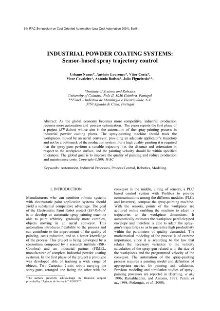
6th IFAC Symposium on Cost Oriented Automation (Low Cost Automation 2001), Berlin.<strong>INDUSTRIAL</strong> <strong>POWDER</strong> <strong>COATING</strong> <strong>SYSTEMS</strong>:Sensor-based spray trajectory controlUrbano Nunes*, António Lourenço*, Vitor Costa*,Vitor Cavaleiro*, António Batista*, João Figueiredo**,*Institute of Systems and RoboticsUniversity of <strong>Coimbra</strong>, Polo II, 3030 <strong>Coimbra</strong>, Portugal**Fimel – Indústria de Metalurgia e Electricidade, S.A.3750 Aguada de Cima, PortugalAbstract: As the global economy becomes more competitive, industrial productionrequires more automation and process optimization. The paper reports the first phase ofa project (EP-Robot) whose aim is the automation of the spray-painting process inindustrial powder coating plants. The spray-painting machine should track theworkpieces moved by an aerial conveyor, providing an adequate applicator’s trajectoryand not be a bottleneck of the production system. For a high quality painting it is requiredthat the spray-guns perform a suitable trajectory, i.e. the distance and orientation inrespect to the workpiece surface, and the painting velocity should lie within specifiedtolerances. The global goal is to improve the quality of painting and reduce productionand maintenance costs. Copyright ©2001 IFACKeywords: Automation, Industrial Processes, Process Control, Robotics, Modeling.1. INTRODUCTIONManufacturers who can combine robotic systemswith electrostatic paint application systems shouldyield a substantial competitive advantage. The goalof the Electrostatic Paint Robot project (EP-Robot) 1is to develop an automatic spray-painting machineable to paint arbitrary, gradually more complex,objects moving in an aerial conveyor. Thisautomation introduces flexibility to the process andcan contribute to the improvement of the quality ofpainting, costs reduction, and to a better knowledgeof the process. This project is being developed by aconsortium composed by a research institute (<strong>ISR</strong>-<strong>Coimbra</strong>) and an industrial partner (FIMEL,manufacturer of complete industrial powder coatingsystems). In the first phase of the project a prototypewas developed able of tracking a wide range ofobjects. Two Cartesian 2-axis robots carrying thespray-guns, arranged one facing the other with the_____________________1 The authors gratefully acknowledge the financial supportprovided by “Agência de Inovação” ADI/FCTconveyor in the middle, a ring of sensors, a PLCbased control system with Profibus to providecommunications among the different modules (PLCsand Inverters), compose the spray-painting machine.With the sensors, points of the workpiece areacquired online enabling the machine to adapt itstrajectories to the workpiece dimensions. Itautomatically estimates the workpiece parallelepipedenvelope and therefore is able to adapt the spraygun’strajectories so as to guarantee high productivitywithin the parameters of quality demanded. Themathematical modeling of the process is of extremeimportance, since it is according to the law thatrelates the necessary variables to the velocitycalculation of the spray-gun related with the size ofthe workpieces and the programmed velocity of theconveyor. The automation of the spray-paintingprocess requires a painting model and definition ofappropriate metrics for painting task validation.Previous modeling and simulation studies of spraypaintingprocesses are reported in (Hertling, et al.,1996; Ramabhadran, and Antonio, 1997; Penin, etal., 1998; Potkonjak, et al., 2000).
Fig. 2. Spray-painting task geometry assuming a plane surface. Left)- spray-cone model as a simplified model ofthe powder spray cloud; Right)- painting trajectory: the rectangle represents the workpiece surface and inthe same figure is superimposed the spray-gun trajectory. In the figure is shown the particular situation inthat the spray projection diameter is equal to the path width: a = b.4.1 Process variablesIn order to optimize the deposition of paint onto thesurface, the spray-gun should be properly positionedand oriented relatively to the surface.Assumption 1: A simplified model assuming that theworkpiece has a parallelepiped shape whichcompletely encloses the workpiece is adopted in thiswork.Assumption 2: the solution space is constrained byassuming that the spraying is carried out at aconstant distance and keeping the nozzle axisorthogonal to the plane surface.Under these assumptions, the robot x -axis does notmove while it paints the same workpiece. Changes inthe x position can only occur during the transitiontime between workpieces. So in the sequel analysiswe ignore the horizontal motion. The sprayingperformed at a constant speed ensures a nearlyuniform film thickness. This fact leads us to analyzethe spraying motion problem under the constraintv = v 0 = constant(1)where v denotes the speed of the spraying motionand v 0 a constant subject to the restrictionswherev0 ≥ max(vy ,vz)(2)vmin≤ v0≤ vmax(3)v y and v z are the conveyor and the verticalspeeds respectively. The inequality (3) states that thespraying speed is confined to a certain interval ofvalues so that the coating thickness be within anadmissible band about the desired value. Thespraying speed is related with the coating time whichdepends on the kind of powder, its flux of sprayingthrough the spray-gun and the raw material of theworkpieces (e.g. iron, steel, aluminum). A minimumtime of coating exists above which the spray-paintingshould be done so that the workpiece areas can behomogeneously coated. On the other hand, if thecoating time is too long, the odds is that the powdermay be detached. Due to the electromagneticcharacteristics of the process, the spray-guns willhave to keep a compulsory distance from theworkpiece never less than 50 mm, once that insmaller distances there is the risk of electric arcs. Fora high transfer efficiency the distance should be lessthan 300 mm. A spray-cone model is assumed as asimplified model of the powder spray cloud, asdepicted in Fig.2. The spray projection diameter adepends on the spaying distance d and spray-coneangle φ :a = 2d tg(φ / 2)(4)The spraying trajectory projected on the workpiecesurface is a periodic function, of period b , as shownin Fig.2. This period is designated path width. Itsvalue is settled from the knowledge of the systemparameters d and φ , and should be in the range0 < b ≤ a(5)
so that it does not remain any area of the surfacewithout being coated. In Fig.2 is shown a particularcase in that the path width is equal to the sprayprojection diameter (i.e. b = a ). In this case thesurface is completely covered with the minimum ofpaint overlapping. Without considering yet the nonlinearitiesof the motion at the workpiece extremities,due to the reversal of the direction of the motion, thevertical speed is related with the height of theworkpiece, conveyor speed and path width as follows2hvyvz= . (6)bThe spraying is performed at the linear speedwithv zv = . (7)cos θ⎛ b ⎞cos( θ ) = 1+⎜ ⎟ (8)⎝ 2h⎠To introduce more precision to the model, we nowconsider the non-linearities of the motion. We defineexclusively as nonlinear areas the exteriorcirculation, outside the rectangle, corresponding tothe break/acceleration ramps (see Figs 2 and 5). FromFig.5 one gets the equation concerning the linear partof the spray-gun trajectorybλ = − v y × t r(9)2where the second term of λ is the distance traveledby the workpiece while the spray-gun reverse itsdirection. To reflect (9) in the calculation of thevertical and spraying speeds, it is enough tosubstitute b / 2 by λ in (6) and (8).4.2 Motion PlanningUnder condition (1), the motion of paint depositiononto the surface describes a periodic trajectory asdepicted in Fig.2 which is traversed at the constantlinear velocity2 2y + v z =v = v v(10)If the speed of the conveyor increases the verticalspeed must decrease to maintain valid the condition(1). The angle θ defined in Fig. 2 increases in thiscase. Herein, we assume that0 ≤ θ ≤ π / 2(11)The upper bound θ = π / 2 defines the state⎧vy = v⎨(12)⎩vz= 0for which the spraying is done only in the horizontalwith the conveyor reaching the prescribed sprayingspeed (note that the motions are in oppositedirections). On the other hand, θ = 0 occurswhenever the conveyor is stopped and the verticalaxis moves at the prescribed spraying speed:02⎧vy = 0⎨⎩vz= v(13)If there was freedom to control the conveyor speed,say for example if there was a dedicated conveyorexclusively to the spray-painting process, we couldplan more easily trajectories to ensure a complete andnearly uniform coverage of the workpiece surface. Apossibility could be to stop the workpiece whilespraying it in the vertical, and move it incrementallyto a new position during the time of reversal ofdirection of the vertical motion. This procedure is notallowed in our case since the conveyor is common toall phases of the powder coating system. Therefore,the speed of the conveyor, which is normallyunchanged for long periods of time, is not a controlvariable for us but an input to be taken into accountwhen calculating online the speed of the vertical axis.Now we can state the trajectory planning problem aswe faced it in the first phase of our EP-Robot project.Problem: Given an admissible conveyor speedv = (14)y v y0determine the vertical speedv = f ( h,b,)(15)z v y0where h , b , and v y 0are the workpiece height, pathwidth, and the conveyor speed, respectively.To analyze the problem consider the case depicted inFig.2 with b = a . If the height increases the verticalspeed must increase proportionally so that the surfacecontinue to be completely covered. This implies thatthe spray-painting speed increases too. In order tomaintain the coating thickness within the tolerancelimits, and as much as possible with values in thevicinity of the desired value, a plausible solutionwould be to increase the delivery volume of theinjectors, in order words to increase the flux ofpowder. The automatic control of the flux is notpracticable with the actual devices incorporated inthe powder coating systems produced by the factory.So, given this constraint we can only aspire toachieve thickness values within an admissible bandabout the desired value. Next two approaches to thetrajectory planning problem are formulated.Approach I: a constant path width is prescribedwhich implies a range of values to the spraying speedfunction of a range of workpiece heights:Set b = b0, with b0≤ a(16)for h ∈ h , h ⇒ v ∈ v , v[ ] [ ]minmaxNotice that the spraying speed values are in practiceupper bounded (Eq. (3)) so that a minimumadmissible film thickness can be guaranteed.Obviously this implies in its turn also an upper boundto the workpiece heights which can be with greatprobability less than h max .12
Fig.3. Sensor ring of the EP-Robot prototypeApproach II: a constant spraying speed is prescribedwhich implies a range of values to the path widthfunction of the range of workpiece heights:Set v = v0,(17)for h ∈ h , h ⇒ b ∈ b , b[ ] [ ]minmaxSince in any circumstance b can be higher than a ,this means that the workpiece height may be inpractice upper bounded by a value less than h max .Both approaches can lead to limitations in themaximum value allowed to the workpiece height(above h max ). In practice this problem is surpassedby using three spray-guns lined up either vertically orhorizontally (see Fig. 4 that shows an image of thespray-guns configuration used in the EP-Robotprototype installed in the industrial plant). Thehorizontal arrangement gives rise to three trajectorieswith the same period but with different phases whichare function of the distances among the guns.5. EXPERIMENTAL RESULTSThe EP-Robot is installed in a continuous workingindustrial powder coating plant since February 2001.Some results were acquired in full process oflaboring, therefore suffering from imposedrestrictions by the normal process of industrialproduction. The tests could not be destructive and theworkpieces were imposed by the production. In thissection an analysis concerning experimental datawhich was periodically acquired by the qualitydepartment is performed. The data concern to thepainting of book-shelves (see Fig. 4) with an area of21× 0,3m. The book-shelves are plane surfaces withsalient borders which are difficult to paint due to theFaraday effect. The EP-Robot was equipped withthree Corona spray-guns, horizontally lined up. Theanalysis is based on two experimental data setscomposed by measures of the film thickness at the12Fig.4. EP-Robot prototype carrying three spray-gunshorizontally line-upFig.5. Painting trajectory projected on the surfacecentral point of the book-shelves (see Fig.4), takenduring approximately three weeks. The beginning ofthe collection of data occurred just after theinstallation of the EP-Robot in the production line.One set is concerned with painting done by the EP-Robot and the other with manual painting. Filmthickness frequencies of the manual and automaticpainting are illustrated in Figs 6 and 7, respectively.The ideal film thickness is around50 µ m and no partof the piece should have a thickness less than 30 µ m .A major requirement is to achieve great uniformity ofthe film thickness. In manual production this featuredepends on the operator’s ability and experience inpositioning, orientating, and moving the spray-gunsmoothly and around a certain constant speed. Fromthis set of results we cannot conclude in whatconcerns the film thickness along the surface (a paintquality analyses will be presented elsewhere).However, a better consistency in film thickness,around a reference value, results for the automaticpainting. For both cases about 57 % of results liewithin the desired band of [ 40 ,60] µ m . However atendency for overpainting and a greater number of
10Mean Value=61.02180Frequency98765432100 20 40 60 80 100 120Film Thickness (µm)140 160 180Film tickness160140120100806040200ManualAutomaticFig. 6. Film thickness frequencies for manualpainting.Fig. 8. Same data sets of Fig. 6 and 7, with manualand automatic data superimposed and shown inits index order of gathering.10Mean Value=48.606. CONCLUSIONS AND FURTHER WORKFrequency98765432100 20 40 60 80 100 120 140 160 180Fig. 7. Film thickness frequencies for automaticpainting.too high thickness values occur in manual painting.An important benefit of the robotic painting is thepossibility to make parameter adjustments with agradual improvement of the painting quality and atthe same time reducing costs. The knowledge of theprocess and the influence of its variables in the finalresult is made possible with the process automation.Fig. 8 shows the same data sets, but with the manualand robotic data superimposed and shown in its indexorder of gathering. During the data gathering timesome adjustments were made in the process with thepurpose of improving the thickness that was initiallyin the mean slightly below the ideal value. From Fig.8 we observe a slight improvement in the thicknessof robot painting. The data in the right window ofFig.8 are more concentrated in the desired band of40 ,60 µ which contains about 63% of the results.[ ] mFilm tickness (µm)To capture online more general piece shapes, othersolutions will be investigated by fusing data fromother sensor modalities, namely vision systems. Theglobal aim is to develop an automatic spray-paintingmachine that improves the quality of painting and atthe same time leads to the reduction of the productionand maintenance costs. In order to compete, acompany should continue the automation of theirproduction lines. In doing so, hazard identificationand control, and online malfunction detection, havebecome increasingly important to protect costlysystems, ensure the safety of personnel and guaranteethe quality of the production. This is another line ofresearch being pursued in the EP-Robot project.REFERENCESHeterling, P., L. Hog, R. Larsen, J. Perran, and H.Peterson (1996). Task Curve Planning forPainting Robots – Part I: Process Modeling andCalibration. In: IEEE Trans. RA, vol. 12, nº2,324:330.Ramabhadran, R. and J. K. Antonio (1997).FastSolution Techniques for a Class of OptimalTrajectory Planning Problems with Applicationsto Automated Spray Coating, In: IEEE Trans.RA , vol. 13, nº4, 519-530.Penin, L., C. Balaguer, J. Pastor, F. Rodríguez, A.Barrientos, and R. Aracil (1998). RobotizedSpraying of Prefabricated Panels. In: IEEE Rob.& Automation Magazine, vol. 5, nº3, 18-29.Potkonjak, V., Dordevic, G.S., Kostic D., Rasic, M.(2000). Dynamics of anthropomorphic paintingrobot: Quality analysis and cost reduction. In:Int. Journ. on Robotics and AutonomousSystems, vol. 32, 17:38.