Scalable Multi Phase Interleaved Boundary Mode PFC Concept ...
Scalable Multi Phase Interleaved Boundary Mode PFC Concept ...
Scalable Multi Phase Interleaved Boundary Mode PFC Concept ...

You also want an ePaper? Increase the reach of your titles
YUMPU automatically turns print PDFs into web optimized ePapers that Google loves.
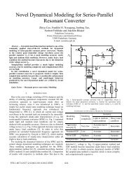
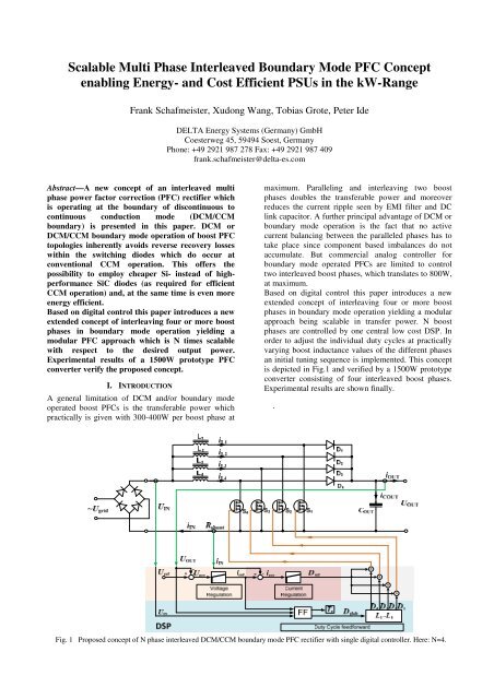
<strong>Scalable</strong> <strong>Multi</strong> <strong>Phase</strong> <strong>Interleaved</strong> <strong>Boundary</strong> <strong>Mode</strong> <strong>PFC</strong> <strong>Concept</strong>enabling Energy- and Cost Efficient PSUs in the kW-RangeFrank Schafmeister, Xudong Wang, Tobias Grote, Peter IdeDELTA Energy Systems (Germany) GmbHCoesterweg 45, 59494 Soest, GermanyPhone: +49 2921 987 278 Fax: +49 2921 987 409frank.schafmeister@delta-es.comAbstract—A new concept of an interleaved multiphase power factor correction (<strong>PFC</strong>) rectifier whichis operating at the boundary of discontinuous tocontinuous conduction mode (DCM/CCMboundary) is presented in this paper. DCM orDCM/CCM boundary mode operation of boost <strong>PFC</strong>topologies inherently avoids reverse recovery losseswithin the switching diodes which do occur atconventional CCM operation. This offers thepossibility to employ cheaper Si- instead of highperformanceSiC diodes (as required for efficientCCM operation) and, at the same time is even moreenergy efficient.Based on digital control this paper introduces a newextended concept of interleaving four or more boostphases in boundary mode operation yielding amodular <strong>PFC</strong> approach which is N times scalablewith respect to the desired output power.Experimental results of a 1500W prototype <strong>PFC</strong>converter verify the proposed concept.I. INTRODUCTIONA general limitation of DCM and/or boundary modeoperated boost <strong>PFC</strong>s is the transferable power whichpractically is given with 300-400W per boost phase atmaximum. Paralleling and interleaving two boostphases doubles the transferable power and moreoverreduces the current ripple seen by EMI filter and DClink capacitor. A further principal advantage of DCM orboundary mode operation is the fact that no activecurrent balancing between the paralleled phases has totake place since component based imbalances do notaccumulate. But commercial analog controller forboundary mode operated <strong>PFC</strong>s are limited to controltwo interleaved boost phases, which translates to 800W,at maximum.Based on digital control this paper introduces a newextended concept of interleaving four or more boostphases in boundary mode operation yielding a modularapproach being scalable in transfer power. N boostphases are controlled by one central low cost DSP. Inorder to adjust the individual duty cycles at practicallyvarying boost inductance values of the different phasesan initial tuning sequence is implemented. This conceptis depicted in Fig.1 and verified by a 1500W prototypeconverter consisting of four interleaved boost phases.Experimental results are shown finally..Fig. 1 Proposed concept of N phase interleaved DCM/CCM boundary mode <strong>PFC</strong> rectifier with single digital controller. Here: N=4.
The paper is structured as follows. Section IIdescribes the basic mode of operation and control of theinterleaved <strong>PFC</strong>. In Section III some simulation resultsare shown in order to document the basic waveforms.The DSP implementation is briefly presented inSection IV. First experimental results obtained on a fourphase interleaved DCM boundary mode <strong>PFC</strong> stage of a1.5kW power supply unit (PSU) are given in Section V.Finally some conclusions and prospects are addressed inSection VI.II. BASIC PRINCIPLEBasically there are different approaches to control Ninterleaved phases in a way that they all stay in DCM orboundary mode operation on the one hand and that onthe other hand the current sum of all phases follows agiven reference value with minimum ripple. By theauthors considered methods were a) a variant of peakcurrent control, b) hysteresis control and c) PWMcontrol. PWM control turned out to be the mostpromising option for robust implementation.So Fig.2 shows principle phase current waveforms asresulting from the PWM method. It is to mention that allinductance values L 1 -L 4 were considered to havedifferent values here (as in practice magneticcomponents may vary by ±10% of the nominal value).The phase with largest inductance value corresponds tothe red current waveform in Fig.2 – this is the ‘masterphase’ which determines the common duty cycle for allphases (at given switching frequency). This has to be the(only) phase which in ideal case operates without DCMinterval. The other phases will have to show a DCMinterval as long as their values L 2 -L 4 are smaller than L 1 .Would one of the L 2 -L 4 values be larger than L 1 then thecorresponding phase current would run into CCMoperation. This should be strictly avoided in order not tosuffer from the arising reverse recovery losses.As a consequence the phase with the largestinductance value has to be identified by the controllerprior to the normal <strong>PFC</strong> operation. This is done withinan initial calibration sequence testing each individualphase inductance (also cf. Fig.4, Fig.8).Although showing potentially different inductancevalues the duty cycles of the ‘slave phases’ can beindividually increased slightly in order to exactly matchthe desired reference value of local average current.Fig.2 illustrates this situation of equal local averages.Fig. 2 PWM controlled interleaved phase currents in case ofunequal inductance values. Here a feed forward adaption isdone in order to get equal local average values for i L1,2,3,4.But nevertheless, the ‘slave phases’ will still have aDCM interval.To exemplify the corresponding feed forwardcalculation of duty cycles we refer to Fig.3. Here the redcurrent curve obviously characterizes the master phase(phase 1). For the general case of DCM the duty cycle d nin dependency of local average current i is given by · · , (1)· where T p is the switching period and all other quantitiescan be found in Fig.1.Correspondingly, the adapted slave duty cycle d 2 can besimply calculated by · . (2)Fig. 3 Different duty cycles for different inductance valueslead to identical local average values of phase currents.For the optional case of boundary mode modulation withthe master phase operating (with some margin) as closeas possible at the DCM/CCM limit also the switchingfrequency f p =1/T p has to be varied and can bedetermined by another feed forward equation: 2 · , · · (3)Therein d c,max defines the maximum relative currentconduction duty of the master inductance (L 1 ) to setmarginally smaller than 1.Apart from setting this passive margin to avoid theunwanted transition to CCM operation when operatingclose to the boundary the currently available (low cost)DSPs from different vendors offer the use of internal onchipcomparators for tasks like this. Their referencethreshold can be varied dynamically and a suddenlyrising current (DCM→CCM) can be reported to thecontrolling algorithm which further decrements f p .Initial Calibration SequenceThe initial calibration sequence is required to a) find thelargest phase inductance (L 1 ) to identify the ‘masterphase’ and to evaluate the expressions (1) as well asmaybe (3), but also to b) quantify the remaininginductances (L 2 -L 4 ) to slightly adapt their individual dutycycles according to (2).Latter is also optional, just to balance the phase currentslocal averages a bit.


![[ ] Ï - Fachgebiet Leistungselektronik und Elektrische Antriebstechnik](https://img.yumpu.com/51151382/1/184x260/-i-fachgebiet-leistungselektronik-und-elektrische-antriebstechnik.jpg?quality=85)