Gas HEatinG Control Unitrol® 7000 700 sEriEs - Uni-Line
Gas HEatinG Control Unitrol® 7000 700 sEriEs - Uni-Line
Gas HEatinG Control Unitrol® 7000 700 sEriEs - Uni-Line

Create successful ePaper yourself
Turn your PDF publications into a flip-book with our unique Google optimized e-Paper software.
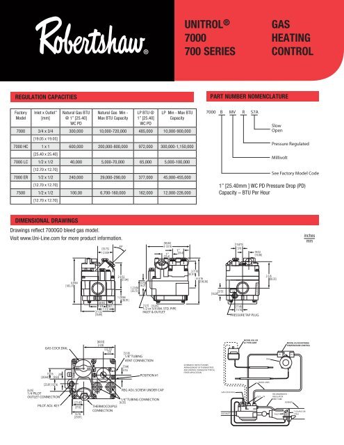
<strong>Uni</strong>trol ®<strong><strong>700</strong>0</strong><strong>700</strong> SERIES<strong>Gas</strong>HEating<strong>Control</strong>REGULATION CAPACITIESPART NUMBER NOMENCLATUREFactoryModelInlet x Outlet”[mm]Natural <strong>Gas</strong> BTU@ 1” [25.40]WC PDNatural <strong>Gas</strong> Min -Max BTU CapacityLP BTU @1” [25.40]WC PDLP Min - Max BTUCapacity<strong><strong>700</strong>0</strong> 3/4 x 3/4 300,000 10,000-720,000 485,000 10,000-900,000[19.05 x 19.05]<strong><strong>700</strong>0</strong> HC 1 x 1 600,000 200,000-800,000 972,000 300,000-1,150,000[25.40 x 25.40]<strong><strong>700</strong>0</strong> LC 1/2 x 1/2 40,000 5,000-70,000 65,000 5,000-100,000[12.70 x 12.70]<strong><strong>700</strong>0</strong> ER 1/2 x 1/2 240,000 29,000-290,00 377,000 45,000-455,000[12.70 x 12.70]7500 1/2 x 1/2 100,00 6,<strong>700</strong>-160,000 162,000 12,000-226,000[12.70 x 12.70]<strong><strong>700</strong>0</strong> B MV R S7ASlowOpenPressure RegulatedMillivoltSee Factory Model Code1” [25.40mm ] WC PD Pressure Drop (PD)Capacity – BTU Per HourDIMENSIONAL DRAWINGSDrawings reflect <strong><strong>700</strong>0</strong>GO bleed gas model.Visit www.<strong>Uni</strong>-<strong>Line</strong>.com for more product information.45º[33.73]1-21/64[96.84]3-13/161”[25.4]1”[25.4][15.875]5/819/32[15.08]inchesmm4-9/64[105.17][34.93]1-3/8 [38.1]1-1/23-1/32[76.99]2-9/32[57.94]41/64[16.27]1-21/64[33.73]1-29/64[36.91][12.7] [19.05]1/2 or 3/4 AM. STD. PIPEINLET & OUTLET2-7/16[61.91]4-3/16[106.36]23/32[18.20]PRESSURETAPFILTER 2CFM[17.46]11/16PRESSURE TAP PLUG2-3/8[60.33]GAS COCK DIAL[60.33]2-3/8[22.33]7/8[3.18]1/8” TUBINGVENT CONNECTIONMODEL KXL ORLC TYPE LIMITDIALINMODEL GS ADJUSTABLETEMPERATURE CONTROLOUT13/16 3/8[20.64] [9.53]INUNITROLONOFFVENT[7.94]5/16POSITION #1SCHEMATIC SKETCH SHOWSARRANGEMENT OF THERMOSTATSAND UNITROL <strong><strong>700</strong>0</strong>BGO IN TYPICALFRYER APPLICATION[23.81] 15/16[6.35]1/4 PILOTOUTLET CONNECTIONPILOT ADJ. KEY[21.43]27/3215/16[23.81]OUTINTHERMOCOUPLECONNECTIONREG ADJ. SCREW UNDER CAP1/4” TUBING CONNECTION[6.35]GAS COCK DIALGAS INLETBLEED LINESOUT INRECOMMENDEDREGULATORVENT TUBEBURNERT COUPLE ORPILOTT PILE