Multi-Protocol Label Switching (MPLS) Conformance and ... - Ixia
Multi-Protocol Label Switching (MPLS) Conformance and ... - Ixia
Multi-Protocol Label Switching (MPLS) Conformance and ... - Ixia

Create successful ePaper yourself
Turn your PDF publications into a flip-book with our unique Google optimized e-Paper software.
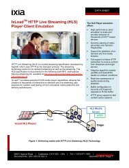
Advantages of <strong>MPLS</strong><strong>MPLS</strong> is atechnology used foroptimizing trafficforwarding througha network.• <strong>MPLS</strong> enables a single converged network to support both new <strong>and</strong> legacy services,creating an efficient migration path to an IP-based infrastructure. <strong>MPLS</strong> operates overboth legacy (DS3, SONET) <strong>and</strong> new infrastructure (10/100/1000/10G Ethernet) <strong>and</strong>networks (IP, ATM, Frame Relay, Ethernet, <strong>and</strong> TDM).• <strong>MPLS</strong> enables traffic engineering. Explicit traffic routing <strong>and</strong> engineering helpsqueeze more data into available b<strong>and</strong>width.• <strong>MPLS</strong> supports the delivery of services with Quality of Service (QoS) guarantees.Packets can be marked for high quality, enabling providers to maintain a specified lowend-to-end latency for voice <strong>and</strong> video.• <strong>MPLS</strong> reduces router processing requirements, since routers simply forward packetsbased on fixed labels.• <strong>MPLS</strong> provides the appropriate level of security to make IP as secure as Frame Relayin the WAN, while reducing the need for encryption on public IP networks.• <strong>MPLS</strong> VPNs scale better than customer-based VPNs since they are provider-networkbased,reducing the configuration <strong>and</strong> management requirements for the customer.How Does <strong>MPLS</strong> Work?<strong>MPLS</strong> is a technology used for optimizing traffic forwarding through a network.Though <strong>MPLS</strong> can be applied in many different network environments, this discussion willfocus primarily on <strong>MPLS</strong> in IP packet networks — by far the most common application of<strong>MPLS</strong> today.<strong>MPLS</strong> assigns labels to packets for transport across a network. The labels are contained inan <strong>MPLS</strong> header inserted into the data packet (Figure 1).These short, fixed-length labels carry the information that tells each switching node(router) how to process <strong>and</strong> forward the packets, from source to destination. They havesignificance only on a local node-to- node connection. As each node forwards the packet,it swaps the current label for the appropriate label to route the packet to the next node.This mechanism enables very-high-speed switching of the packets through the core <strong>MPLS</strong>network.<strong>MPLS</strong> combines the best of both Layer 3 IP routing <strong>and</strong> Layer 2 switching. In fact, it issometimes called a “Layer 2½” protocol. While routers require network-level intelligenceto determine where to send traffic, switches only send data to the next hop, <strong>and</strong> so areinherently simpler, faster, <strong>and</strong> less costly. <strong>MPLS</strong> relies on traditional IP routing protocolsto advertise <strong>and</strong> establish the network topology. <strong>MPLS</strong> is then overlaid on top of thistopology. <strong>MPLS</strong> predetermines the path data takes across a network <strong>and</strong> encodes thatinformation into a label that the network’s routers underst<strong>and</strong>. This is the connectionorientedapproach previously discussed. Since route planning occurs ahead of time <strong>and</strong> atthe edge of the network (where the customer <strong>and</strong> service provider network meet), <strong>MPLS</strong>labeleddata requires less router horsepower to traverse the core of the service provider'snetwork.6
<strong>MPLS</strong> routing<strong>MPLS</strong> networks establish <strong>Label</strong>-Switched Paths (LSPs) for data crossing the network. AnLSP is defined by a sequence of labels assigned to nodes on the packet’s path from sourceto destination. LSPs direct packets in one of two ways: hop-by-hop routing or explicitrouting.Hop-by-hop routing. In hop-by-hop routing, each <strong>MPLS</strong> router independently selectsthe next hop for a given Forwarding Equivalency Class (FEC). A FEC describes a groupof packets of the same type; all packets assigned to a FEC receive the same routingtreatment. FECs can be based on an IP address route or the service requirements for apacket, such as low latency.Figure 1. <strong>MPLS</strong> header format on an <strong>MPLS</strong> packet.In the case of hop-by-hop routing, <strong>MPLS</strong> uses the network topology informationdistributed by traditional Interior Gateway <strong>Protocol</strong>s (IGPs) — routing protocols such asOSPF or IS-IS. This process is similar to traditional routing in IP networks, <strong>and</strong> the LSPsfollow the routes the IGPs dictate.Explicit routing. In explicit routing, the entire list of nodes traversed by the LSP isspecified in advance. The path specified could be optimal or not, but is based on theoverall view of the network topology <strong>and</strong>, potentially, on additional constraints. This iscalled Constraint-Based Routing.Along the path, resources may be reserved to ensure QoS. This permits traffic engineeringto be deployed in the network to optimize use of b<strong>and</strong>width.<strong>Label</strong> Information Base. As the network is established <strong>and</strong> signaled, each <strong>MPLS</strong> routerbuilds a <strong>Label</strong> Information Base (LIB)—a table that specifies how to forward a packet. Thistable associates each label with its corresponding FEC <strong>and</strong> the outbound port to forwardthe packet to.In the case of hopby-hoprouting,<strong>MPLS</strong> uses thenetwork topologyinformationdistributed bytraditional InteriorGateway <strong>Protocol</strong>s(IGPs) — routingprotocols such asOSPF or IS-IS.This LIB is typically established in addition to the routing table <strong>and</strong> Forwarding InformationBase (FIB) that traditional routers maintain.7
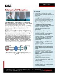
Signaling <strong>and</strong> label distributionConnections aresignaled <strong>and</strong> labelsare distributedamong nodes inan <strong>MPLS</strong> networkusing one of severalsignaling protocols,including <strong>Label</strong>Distribution <strong>Protocol</strong>(LDP) <strong>and</strong> ResourcereSerVation <strong>Protocol</strong>with TunnelingExtensions (RSVP-TE).Connections are signaled <strong>and</strong> labels are distributed among nodes in an <strong>MPLS</strong> networkusing one of several signaling protocols, including <strong>Label</strong> Distribution <strong>Protocol</strong> (LDP) <strong>and</strong>Resource reSerVation <strong>Protocol</strong> with Tunneling Extensions (RSVP- TE). Alternatively, labelassignment can be piggybacked onto existing IP routing protocols such as BGP.The most commonly used <strong>MPLS</strong> signaling protocol is LDP. LDP defines a set ofprocedures used by <strong>MPLS</strong> routers to exchange label <strong>and</strong> stream mapping information. Itis used to establish LSPs, mapping routing information directly to Layer 2 switched paths.It is also commonly used to signal at the edge of the <strong>MPLS</strong> network — the critical pointwhere non-<strong>MPLS</strong> traffic enters. Such signaling is required when establishing <strong>MPLS</strong> VPNs,for example.RSVP-TE is also used for label distribution, most commonly in the core of networks thatrequire traffic engineering <strong>and</strong> QoS. A set of extensions to the original RSVP protocol,RSVP-TE provides additional functionality beyond label distribution, such as explicitLSP routing, dynamic rerouting around network failures, preemption of LSPs, <strong>and</strong> loopdetection. RSVP-TE can distribute traffic engineering parameters such as b<strong>and</strong>widthreservations <strong>and</strong> QoS requirements.<strong>Multi</strong>-protocol extensions have been defined for BGP, enabling the protocol to also be usedto distribute <strong>MPLS</strong> labels. <strong>MPLS</strong> labels are piggybacked onto the same BGP messagesused to distribute the associated routes.<strong>MPLS</strong> allows multiple labels (called a label stack) to be carried on a packet. <strong>Label</strong> stackingenables <strong>MPLS</strong> nodes to differentiate between types of data flows, <strong>and</strong> to set up <strong>and</strong>distribute LSPs accordingly. A common use of label stacking is for establishing tunnelsthrough <strong>MPLS</strong> networks for VPN applications.Figure 2. <strong>MPLS</strong> network.8
Data flow in an <strong>MPLS</strong> networkFigure 2 shows a typical <strong>MPLS</strong> network <strong>and</strong> its associated elements. The central cloudrepresents the <strong>MPLS</strong> network itself. All data traffic within this cloud is <strong>MPLS</strong>- labeled.All traffic between the cloud <strong>and</strong> the customer networks is not <strong>MPLS</strong>- labeled (IP forexample). The customer- owned Customer Edge (CE) routers interface with the ProviderEdge (PE) routers (also called <strong>Label</strong> Edge Routers, or LERs) owned by the serviceprovider. At the ingress (incoming) side of the <strong>MPLS</strong> network, PE routers add <strong>MPLS</strong> labelsto packets. At the egress (outgoing) side of the <strong>MPLS</strong> network, the PE routers remove thelabels. Within the <strong>MPLS</strong> cloud, P (Provider) routers (also called <strong>Label</strong> <strong>Switching</strong> Routers,or LSRs), switch traffic hop-by-hop based on the <strong>MPLS</strong> labels.To demonstrate an <strong>MPLS</strong> network in operation, we will follow the flow of data through thenetwork in Figure 2:1. Before traffic is forwarded on the <strong>MPLS</strong> network, the PE routers first establish LSPsthrough the <strong>MPLS</strong> network to remote PE routers.2. Non-<strong>MPLS</strong> traffic (Frame Relay, ATM, Ethernet, etc.) is sent from a customer network,through its CE router, to the ingress PE router operating at the edge of the provider’s<strong>MPLS</strong> network.3. The PE router performs a lookup on information in the packet to associate it with aFEC, then adds the appropriate <strong>MPLS</strong> label(s) to the packet.4. The packet proceeds along its LSP, with each intermediary P router swapping labelsas specified by the information in its LIB to direct the packet to the next hop.5. At the egress PE, the last <strong>MPLS</strong> label is removed <strong>and</strong> the packet is forwarded bytraditional routing mechanisms.6. The packet proceeds to the destination CE <strong>and</strong> into the customer’s network.How Is <strong>MPLS</strong> Used?One of the primary original goals of <strong>MPLS</strong>, boosting the performance of software- basedIP routers, has been superseded as advances in silicon technology have enabled line-raterouting performance implemented in router hardware. In the meantime, additional benefitsof <strong>MPLS</strong> have been realized, notably VPN services <strong>and</strong> traffic engineering.Virtual Private NetworksOne of the primaryoriginal goals of<strong>MPLS</strong>, boostingthe performance ofsoftware- based IProuters, has beensuperseded asadvances in silicontechnology haveenabled line-raterouting performanceimplemented inrouter hardware.A Virtual Private Network (VPN) is a private network service delivered over a public(shared) network. VPNs benefit end customers by allowing remote locations to besecurely connected over a public network, without the expense of buying or leasingdedicated network lines. <strong>MPLS</strong> enables VPNs by providing a circuit-like, connectionorientedframework, allowing carriers to deploy VPNs over the traditionally connectionlessIP network infrastructure.9
<strong>MPLS</strong> VPNs vs. IPSec VPNs. The term VPN can be confusing, as it is used to describe anumber of technologies. VPNs can be organized into two broad categories:• Customer-based: the VPN is configured exclusively on customer- located equipment<strong>and</strong> uses tunneling protocols across the public network, most commonly IPSec.• Network-based: the VPN is configured on service provider equipment <strong>and</strong> managed bythe provider. <strong>MPLS</strong> VPNs are an example of network-based VPNs.IPSec adds secure encryption capabilities to IP. It is typically managed by the endcustomer, outside of a service provider’s network, where there is a higher degree ofexposure to breaches of data privacy.IPSec is especially useful for securing remote location VPN connections back to thecorporate network.<strong>MPLS</strong> VPNs aremaintained on theservice provider’sequipment, whichcan providesignificant costsavings <strong>and</strong>increased scalabilitycompared with otherVPN technologies.<strong>MPLS</strong> VPNs are maintained on the service provider’s equipment, which can providesignificant cost savings <strong>and</strong> increased scalability compared with other VPN technologies.<strong>MPLS</strong> VPNs keep different customers’ traffic separated by uniquely identifying each VPNflow <strong>and</strong> setting up circuit-like connections. This mechanism provides traffic separation<strong>and</strong> is transparent to end users within the VPN group. <strong>MPLS</strong> VPNs provide securityinherently, essentially making IP as secure as Frame Relay or ATM, <strong>and</strong> reducing the needfor encryption. Miercom, an independent network consultancy <strong>and</strong> testing laboratory,tested <strong>MPLS</strong> VPN security on a network of various routers, <strong>and</strong> concluded (2001): “Ourtest results have demonstrated that <strong>MPLS</strong>-based VPN networks offer the same level ofsecurity as Frame Relay or ATM.”L3 VPNs. <strong>MPLS</strong> VPNs fall into two broad classes — those that operate at Layer 3 <strong>and</strong>those that operate at Layer 2. Layer 3 VPNs were first to be investigated <strong>and</strong> st<strong>and</strong>ardizedin RFCs. Layer 3 VPNs based on RFC 2547bis have seen the most widespread deploymentto date.RFC 2547bis-based Layer 3 VPNs use extensions to BGP, specifically <strong>Multi</strong>- <strong>Protocol</strong>internal BGP (MP-iBGP), to distribute VPN routing information across the providerbackbone. St<strong>and</strong>ard <strong>MPLS</strong> mechanisms (as previously discussed) are used to forward theVPN traffic across the backbone. In an L3 VPN, the CE <strong>and</strong> PE routers are IP routing peers.The CE router provides the PE router with the routing information for the customer’sprivate network behind it. The PE router stores this private routing information in a VirtualRouting <strong>and</strong> Forwarding (VRF) table; each VRF is essentially a private IP network. ThePE router maintains a separate VRF table for each VPN, thereby providing appropriateisolation <strong>and</strong> security. VPN users have access only to sites or hosts within the same VPN.In addition to the VRF tables, the PE router also stores the normal routing information itneeds to send traffic over the public Internet.10
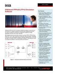
Figure 3. Layer 3 VPN <strong>MPLS</strong> network.L3 VPNs use a two-level <strong>MPLS</strong> label stack (see Figure 3). The inner label carriesVPN- specific information from PE to PE. The outer label carries the hop-by-hop <strong>MPLS</strong>forwarding information. The P routers in the <strong>MPLS</strong> network only read <strong>and</strong> swap the outerlabel as the packet passes through the network. They do not read or act upon the innerVPN label — that information is tunneled across the network.The L3 VPN approach has several advantages. The customer IP address space is managedby the carrier, significantly simplifying the customer IT role — as new customer VPNsites are easily connected <strong>and</strong> managed by the provider. L3 VPNs also have the advantageof supporting auto-discovery by leveraging the dynamic routing capabilities of BGP todistribute VPN routes.The Layer 3 approach has disadvantages as well. Layer 3 VPNs support only IP or “IPencapsulated”customer traffic. Scaling also can be a significant issue with PE routersrequired to support BGP routing tables that are larger than normal with the addition of theVPN routes.L2 VPNs. Layer 2 <strong>MPLS</strong> VPNs have recently generated much interest from carriers <strong>and</strong>vendors <strong>and</strong> are beginning to be deployed (2003). Layer 2 <strong>MPLS</strong> VPN st<strong>and</strong>ards are stillin the development phase, but the industry has centralized on the IETF Martini drafts,named after primary author Luca Martini. These drafts define a method for setting up L2VPN tunnels across an <strong>MPLS</strong> network that can h<strong>and</strong>le all types of Layer 2 traffic, includingEthernet, Frame Relay, ATM, TDM, <strong>and</strong> PPP/HDLC.11
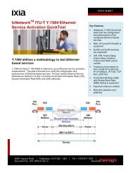
There are two kinds of Layer 2 VPNs that use the Martini methodology:• Point-to-point: similar to ATM <strong>and</strong> Frame Relay using fixed, point-to-point connections(LSPs) across the network.• <strong>Multi</strong>-point: supporting meshed <strong>and</strong> hierarchical topologies.Figure 4. Layer 2 VPN <strong>MPLS</strong> network.VPLS (VirtualPrivate LANServices) is a multipointL2 VPN modelthat has generatedsignificant interestof late.VPLS (Virtual Private LAN Services) is a multi-point L2 VPN model that has generatedsignificant interest of late. VPLS uses Ethernet as the access technology between thecustomer <strong>and</strong> the provider network <strong>and</strong> enables a private corporate Ethernet network tobe extended over a provider-managed <strong>MPLS</strong> infrastructure.<strong>Multi</strong>ple corporate customer sites can be connected together with all locations appearingto be on the same Layer 3 network, all without the complexity of configuring Layer 3routers.In Layer 2 VPNs, the PE <strong>and</strong> CE routers need not be routing peers as required in Layer 3VPNs. Instead, only a Layer 2 connection needs to exist between PE <strong>and</strong> CE, with the PErouters simply switching incoming traffic into tunnels configured to one or more otherPE routers. A Layer 2 <strong>MPLS</strong> VPN determines reachability through the data plane by usingaddress learning, in contrast with Layer 3 VPNs, which determine reachability through thecontrol plane by exchanging BGP routes.L2 VPNs use label stacking similar to Layer 3 VPNs. The outer tunnel label determines thehop-by-hop path through the network.The inner Virtual Circuit (VC) label identifies the VLAN, VPN, or connection at the endpoint. In addition, there is an optional Control Word following the VC label that carriesinformation about the enclosed Layer 2 packet.12
Layer 2 <strong>MPLS</strong> VPNs have the distinct advantage of being able to transport any enterpriseprotocol — whatever is being carried is transparent to the <strong>MPLS</strong> network. They can alsorun over nearly any transport medium, including ATM, Frame Relay, Packet over SONET,<strong>and</strong> Ethernet, enabling the integration of connectionless IP networks with connectionorientednetworks. End customer expertise is minimal since no routing configuration isrequired.On the downside, L2 VPNs may not scale as well as L3 VPNs. A full mesh of LSPs mustbe set up between all L2 VPN sites, a requirement that does not scale well with largenumbers of sites. In addition, they cannot take advantage of automatic route discoveryavailable with L3 VPNs, <strong>and</strong> so are better suited to situations with a smaller number ofVPN sites <strong>and</strong> static routes.QoS/CoSOne of the key shortcomings of IP-based networks, compared with Frame Relay <strong>and</strong> ATMnetworks, has been their inability to provide service guarantees for traffic. For example,real-time traffic such as voice or video needs high quality service (low latency, lowjitter, etc.) to successfully traverse a network. Similarly, mission- critical data, such ase-commerce transactions, must have priority over normal web browser traffic.<strong>MPLS</strong>’s connection-oriented nature provides the framework necessary to give qualityguarantees to IP traffic. While QoS <strong>and</strong> Class of Service (CoS) are not fundamentalfeatures of <strong>MPLS</strong>, they can be applied in <strong>MPLS</strong> networks where traffic engineeringis used. This enables providers to establish Service Level Agreements (SLAs) withcustomers to guarantee service aspects such as network b<strong>and</strong>width, delay, <strong>and</strong> jitter.Value- added services can be delivered in addition to basic data transport, increasingrevenue propositions <strong>and</strong> ultimately enabling the move to converged networks.IntServ <strong>and</strong> DiffServ. Several mechanisms have developed over time to establish QoS/CoS within a network. In the IntServ (Integrated Services) model, RSVP was developedto signal QoS requirements across a network, allowing devices to negotiate <strong>and</strong> establishguaranteed traffic parameters such as b<strong>and</strong>width <strong>and</strong> latency end-to-end. It uses hardallocation of resources, guaranteeing services down to a per-flow basis. The DiffServ(Differentiated Services) model is less stringent, providing for CoS delivery by classifyingtraffic into relative priority levels for aggregate treatment, but without signaling or endto-endguarantees of service. DiffServ redefines the Type of Service (TOS) field in the IPpacket header to provide this classification.One of the keyshortcomings ofIP-based networks,compared withFrame Relay <strong>and</strong>ATM networks, hasbeen their inabilityto provide serviceguarantees fortraffic.While IntServ offers traffic b<strong>and</strong>width guarantees, it has proved to be not very scalableor practical to operate across large networks. The DiffServ architecture, on the otherh<strong>and</strong>, is a scalable alternative, but does not provide guarantees. Recent work in the IETFhas focused on combining DiffServ <strong>and</strong> <strong>MPLS</strong> traffic engineering elements to provideQoS guarantees in <strong>MPLS</strong> packet networks. The DiffServ information in IP packet headersis mapped into the label information of the <strong>MPLS</strong> packets. <strong>MPLS</strong> routers act upon theprioritization information in the packets to forward the data appropriately. Some of themechanisms used include traffic shaping, queuing, <strong>and</strong> packet classification.QoS is typically implemented at the edge of the <strong>MPLS</strong> cloud, where non-labeled trafficfrom the customer network enters the carrier network. At this entry point for example,delay-sensitive real-time traffic, such as IP voice or video conferencing traffic, can beprioritized for delivery over bulk data transmissions.13
Traffic engineeringAnother key shortcoming of IP, especially in public networks, is its inability to optimizenetwork resource utilization. Using st<strong>and</strong>ard IP routing, all traffic between two points issent over the shortest path even though multiple paths may exist. During periods of hightraffic volume, this can result in traffic congestion on certain routes while alternativeroutes are underused. This is known as the hyper- aggregation problem (Figure 5).Rather than adding b<strong>and</strong>width to h<strong>and</strong>le traffic volume increases, <strong>MPLS</strong> traffic engineeringuses existing b<strong>and</strong>width more efficiently by allowing packets to be routed along explicitroutes <strong>and</strong> with specific b<strong>and</strong>width guarantees.Figure 5. Hyper-aggregation in conventional IP networks.Another keyshortcoming of IP,especially in publicnetworks, is itsinability to optimizenetwork resourceutilization.This is known as Constraint-Based Routing <strong>and</strong> is the key to <strong>MPLS</strong> traffic engineering.Constraint-Based Routing manages traffic paths within an <strong>MPLS</strong> network, allowing trafficto be steered to desired paths.<strong>MPLS</strong> traffic engineering also enables resiliency <strong>and</strong> reliability to be built into carriernetworks, increasing the availability <strong>and</strong> value of the network to their customers. Using<strong>MPLS</strong> traffic engineering, LSP connections can be optimized <strong>and</strong> preempted. Whenoutages occur, traffic can be actively rerouted around failed links. An example of this isRSVP-TE Fast Reroute, which provides for sub-50ms switchovers between primary <strong>and</strong>back up LSPs or LSP bundles.Traffic engineering is deployed in <strong>MPLS</strong> networks via traffic engineering extensions toIGPs, such as OSPF <strong>and</strong> IS-IS. OSPF-TE <strong>and</strong> IS-IS-TE carry additional information —suchas link b<strong>and</strong>width, link utilization, delay, priority, preemption, etc. — to allow the networkto utilize paths that meet service requirements, resource availability, load balancing, <strong>and</strong>failure recovery objectives. RSVP-TE is widely used for <strong>MPLS</strong> signaling in networks thatrequire traffic engineering.<strong>MPLS</strong> traffic engineering is typically deployed in the core of the <strong>MPLS</strong> network, while QoSis used at the edge. QoS at the edge ensures that high priority packets get preferentialtreatment, while traffic engineering avoids network congestion <strong>and</strong> appropriately utilizesavailable b<strong>and</strong>width resources. Together, QoS <strong>and</strong> traffic engineering enable organizationsto move away from multiple, specialized networks for voice, video, <strong>and</strong> data to a singleconverged IP/<strong>MPLS</strong> network, dramatically reducing overhead <strong>and</strong> cost.14
<strong>MPLS</strong> Challenges<strong>MPLS</strong> has made significant progress over the last few years <strong>and</strong> is well into mainstreamdeployment in networks around the world. But key challenges to attaining morewidespread acceptance remain. <strong>MPLS</strong> encompasses a wide range of functionality <strong>and</strong>applications, therefore its implementation has an associated high level of complexity.Vendors who develop <strong>MPLS</strong> technology, as well as organizations looking at deploying<strong>MPLS</strong> in a network today, must also factor in <strong>MPLS</strong>’s continually evolving state <strong>and</strong> itsimpact on network performance <strong>and</strong> scalability.<strong>MPLS</strong> is not a st<strong>and</strong>alone technology — it is overlaid on Layer 2 technologies such asEthernet or ATM, <strong>and</strong> must operate in conjunction with other control plane protocols,such as IP routing. The complexity of <strong>MPLS</strong> deployments is increased because of thisinteraction. In some cases, four or more protocols may be involved in a given networkscenario, necessitating careful coordination <strong>and</strong> validation of the end-to-end system.Integration of legacy services <strong>and</strong> deployment of new services, such as VPNs, requirestunneling, which in turn increases the setup requirements for a given circuit.Though under development for a number of years, <strong>MPLS</strong> continues to evolve rapidly. Theprimary goals of the technology have shifted over time as technology has progressed.Today, a number of extensions to the <strong>MPLS</strong> protocols, as well as new functionality, areunder development. New developments often obsolete older ones. This dynamic naturepresents a moving target to those developing <strong>and</strong> deploying <strong>MPLS</strong>. Vendors must decidewhether to implement a new feature with an eye on the industry’s current direction.Service providers gauge the viability of new developments by asking whether they solve agiven problem better. On certain issues, the industry has split into multiple camps, furthercomplicating the situation as organizations trade off the long term risk of obsolescencewith the shorter term benefits of implementing a certain technology. Interoperability of<strong>MPLS</strong> equipment in heterogeneous networks remains an issue <strong>and</strong> will continue to be sofor several years to come.<strong>MPLS</strong> has madesignificant progressover the last fewyears <strong>and</strong> is wellinto mainstreamdeployment innetworks around theworld.Though advances in silicon technology have vastly improved the raw performance oftoday’s routers, the complexity of <strong>MPLS</strong> in real network applications presents performance<strong>and</strong> scalability issues. The challenge is typically not in the <strong>MPLS</strong> core network, wheredata is simply being label- switched, but at the network edge where <strong>MPLS</strong> must integratewith non-<strong>MPLS</strong> networks, <strong>and</strong> where services are initiated. As networks converge, trafficloads increase <strong>and</strong> networks must be able to deal with the overhead of h<strong>and</strong>ling real- time<strong>and</strong> prioritized traffic. The meshed connections required for VPN deployments can quicklychallenge equipment scalability limitations, as well as provisioning <strong>and</strong> managementrequirements. Large service provider networks have the ultimate scalability challenge<strong>and</strong> must consider the limitations of their equipment as they look to maximize return oninvestment.The challenges presented by <strong>MPLS</strong> ultimately necessitate thorough testing <strong>and</strong> validationof <strong>MPLS</strong> systems during development <strong>and</strong> prior to deployment. <strong>MPLS</strong> is by no means aplug-<strong>and</strong>-play proposition. Performing appropriate due diligence is the only way to ensuresuccess when dealing with a broad-scope <strong>and</strong> rapidly evolving technology such as <strong>MPLS</strong>.15
Why Test for <strong>MPLS</strong> <strong>Conformance</strong>?<strong>MPLS</strong> st<strong>and</strong>ards <strong>and</strong> implementations are dynamic. At the time of this writing, therewere over 100 IETF drafts associated with <strong>MPLS</strong>, <strong>and</strong> over 20 RFCs. In such a dynamicenvironment, st<strong>and</strong>ards compliance <strong>and</strong> the corresponding expectation of equipmentinteroperability present significant challenges.Equipment vendors find themselves at the leading edge of these challenges as theycontinually update their feature sets to the latest st<strong>and</strong>ards <strong>and</strong> options, while at the sametime improving performance <strong>and</strong> scalability. They must do this, both to remain competitivein their market <strong>and</strong> to meet the dem<strong>and</strong>s of their customers.Equipment vendorsfind themselves atthe leading edge ofthese challengesas they continuallyupdate their featuresets to the latestst<strong>and</strong>ards <strong>and</strong>options, while at thesame time improvingperformance <strong>and</strong>scalability.Development test <strong>and</strong> quality assurance groups therefore need an efficient way to verifythe correctness of their implementations. Formalized conformance testing againstst<strong>and</strong>ards supplies this confidence. Beyond ensuring product interoperability <strong>and</strong> quality,conformance testing can also accelerate product development by detecting bugs orcorrecting design issues early in the development cycle, thereby reducing the product’stime to market <strong>and</strong> hence increasing profitability.For both service providers <strong>and</strong> enterprise organizations, multi-vendor environments arethe reality today. Such a reality is untenable without equipment interoperability driven byst<strong>and</strong>ards-based implementations. Networks are also dynamic, so when it comes timeto upgrade, conformance <strong>and</strong> regression testing are crucial to ensure that new softwarereleases do not break existing services.To achieve adequate test coverage for compliance with a st<strong>and</strong>ard, hundreds ofconformance test cases are typically necessary to cover a given protocol, <strong>and</strong> these testsmust be appropriately updated as necessary. Since test cycles are often very frequent(daily in some cases), these tests must be automated as well. To address these challenges,most vendors <strong>and</strong> service providers rely on conformance testing products that aremaintained <strong>and</strong> supported by a dedicated third-party.Why Test for <strong>MPLS</strong> Scalability <strong>and</strong> Performance?After verifying the st<strong>and</strong>ards compliance <strong>and</strong> interoperability of an <strong>MPLS</strong> system, the nextchallenge is to determine the ability of an implementation to perform in a real network.Given the complexity of the protocols involved <strong>and</strong> the multi-layered nature of <strong>MPLS</strong>,scalability <strong>and</strong> performance are often genuine concerns. Equipment vendors typically test<strong>and</strong> publish the scalability <strong>and</strong> performance capabilities of their products. End users willoften validate the numbers while additionally testing specific network scenarios unique totheir deployment.ScalabilityScalability is typically viewed as the biggest challenge in service providers’ <strong>MPLS</strong>networks today. They must underst<strong>and</strong> the dynamics of growth in their networks as newcustomers are added, as well as the ultimate limits of their networks. Several metrics arekey in determining scalability:• Router capacity: The capacity of the <strong>MPLS</strong> routers to h<strong>and</strong>le large numbers of LSPs,VPN instances (VRFs or VCs), <strong>and</strong> routes is important to determine when sizing theoverall network.16
• LSP setup rate: The rate at which LSPs can be set up is an important factor in overallnetwork responsiveness.• Signaling protocol scalability: The limits of an <strong>MPLS</strong> router running signalingprotocols such as LDP orRSVP-TE must be verified to determine the number of protocol sessions that can besustained.Together, these numbers will determine the quantity of routers that must be deployed for agiven number of customers.PerformanceOne of the original proposed benefits of <strong>MPLS</strong> was the performance boost associated withswitching on a label as opposed to routing on an IP address. While this is of less concerntoday, the forwarding performance of PE routers at the edge of the <strong>MPLS</strong> network stillinvolves IP (or other) lookups <strong>and</strong> assignments. Vendors <strong>and</strong> service providers alike musttest <strong>and</strong> characterize <strong>MPLS</strong> devices across multiple interface types (Ethernet, POS, ATM)for traditional data plane performance metrics:• Data throughput• Packet loss• Latency• JitterGiven the advances in hardware-based routing in recent years, the expectations for deviceperformance have grown so that line rate traffic support is typically a given. But the <strong>MPLS</strong>routers of today are being asked to perform many functions, with operational requirementsat the data (traffic), control (routing), security, <strong>and</strong> management planes. With requirementsfor <strong>MPLS</strong> routers to run multiple protocols simultaneously, to interoperate amongmultiple technologies, <strong>and</strong> to apply QoS <strong>and</strong> other policies to traffic, the reality is that fullperformance is not a given.One of the originalproposed benefitsof <strong>MPLS</strong> was theperformance boostassociated withswitching on alabel as opposedto routing on an IPaddress.Performance must be viewed in different usage scenarios, depending on how the networkis designed <strong>and</strong> being operated.Together, scalability <strong>and</strong> performance metrics can be competitive differentiators forequipment vendors. For service providers <strong>and</strong> network managers, they are a key selectioncriteria between vendors. Characterizing these elements is critical, since they directlyimpact the service quality that can be delivered to the end customer.Test Solution Requirements<strong>MPLS</strong> test tools must be able to perform a wide variety of functions to test <strong>and</strong> validate<strong>MPLS</strong> devices <strong>and</strong> systems adequately. For conformance testing, the test solution must beable to fully exercise the control plane of the device or system under test. For performance<strong>and</strong> scalability testing, the test solution must be able to emulate <strong>MPLS</strong> routers at thecontrol plane level <strong>and</strong> scale up for large capacity testing. And it must be able to drivetraffic through the system at the data plane level to fully stress the device being tested.17
Optimized hardware platformWhile simple router emulations can be run on PCs or workstations, an optimized testsystem must be employed to provide complete testing capabilities <strong>and</strong> high levels ofscalability. For example, to emulate a large network, a network interface on a testtool must support hundreds or even thous<strong>and</strong>s of IP interfaces <strong>and</strong> MAC addresses—requirements that st<strong>and</strong>ard off-the-shelf hardware cannot support. Purpose-built testhardware is required to provide the flexibility <strong>and</strong> scalability needed to adequately test<strong>MPLS</strong> equipment.Routing protocol emulationThe test solution must be able to emulate the full range of routing protocols used in today’snetworks, including OSPF, IS-IS, RIP, <strong>and</strong> BGP. These routing protocols are used toadvertise the underlying network topologies over which the <strong>MPLS</strong> network is established.In addition, traffic engineering extensions to these protocols, for example OSPF-TE <strong>and</strong>IS-IS-TE, must be supported to allow this aspect of <strong>MPLS</strong> to be tested.Signaling protocol emulation<strong>MPLS</strong> signaling protocols must be supported to establish <strong>MPLS</strong> tunnels <strong>and</strong> signal L2 <strong>and</strong>L3 VPNs. Examples of these protocols include LDP, RSVP-TE, <strong>and</strong> MP- BGP. The test toolmust be able to run these protocols simultaneously with the routing protocols on the samenetwork interface.Traffic generationOnce the <strong>MPLS</strong> network has been established <strong>and</strong> all connections signaled, the test toolmust be able to inject data traffic into the network topology, at speeds up to line rate, <strong>and</strong>it must be able to receive traffic as well. This means sending traffic over all of the LSPsconfigured on the test interfaces. On the receiving side, the test tool must be able togather statistics <strong>and</strong> capture the traffic for analysis. An increasingly common requirementfor test tools is to emulate real enterprise applications over the network. This allows forthe characterization of the network in terms the end user really cares about, namely, howtheir applications will perform.AutomationSince <strong>MPLS</strong> testing involves complex setup <strong>and</strong> analysis requirements, tests must berepeatable, which makes automation very important. Scripting languages are normallyused to provide automation in <strong>MPLS</strong> router testing. These tools enable quality assurance<strong>and</strong> manufacturing environments to perform repeatable regression tests necessary toensure product functionality <strong>and</strong> quality.18
<strong>Ixia</strong>’s Approach to <strong>MPLS</strong> Testing<strong>MPLS</strong> conformance testing<strong>Ixia</strong> has addressed the challenges of protocol conformance testing by developingIxANVL (<strong>Ixia</strong> Automated Network Validation Library), the industry st<strong>and</strong>ard conformancetest suite. While supporting over 30 protocols overall, IxANVL contains over 800 testcases to validate routers for <strong>MPLS</strong> label encapsulation, <strong>and</strong> LDP <strong>and</strong> RSVP-TE protocolconformance. IxANVL provides positive as well as negative test cases against the RFCsthat specify these st<strong>and</strong>ards. Negative tests help validate device response to “killerpackets.”IxANVL performs its tests as a dialog: it sends packets to the router being tested, receivesthe packets sent in response, <strong>and</strong> then analyzes the response to determine the next actionto take. This allows IxANVL to test complicated situations or reactions in a much moreintelligent <strong>and</strong> flexible way than can be done by simple packet generation <strong>and</strong> capturedevices.IxANVL can run on st<strong>and</strong>alone workstations or on <strong>Ixia</strong> test hardware. Its operation can becompletely automated using a scripting interface. IxANVL source code is also available tousers for customization, allowing a great degree of testing flexibility.<strong>MPLS</strong> scalability <strong>and</strong> performance testingThe general methodology employed by <strong>Ixia</strong> for testing the scalability <strong>and</strong> performance of<strong>MPLS</strong> routers involves first surrounding the device or system under test (DUT/SUT) with<strong>Ixia</strong> hardware test interfaces. The <strong>Ixia</strong> system then emulates everything else needed totest the device, including other <strong>MPLS</strong> routers, IP route injection, LSP signaling, <strong>and</strong> traffictransmission. In this way, large <strong>and</strong> complex topologies can be simulated to test the DUT/SUT in realistic system environments, with a minimum of hardware requirements. As anexample, in Figure 6, four <strong>Ixia</strong> test interfaces are connected to the DUT with numerousrouters being emulated per interface.The generalmethodologyemployed by <strong>Ixia</strong>for testing thescalability <strong>and</strong>performance of<strong>MPLS</strong> routersinvolves firstsurrounding thedevice or systemunder test (DUT/SUT) with <strong>Ixia</strong>hardware testinterfaces.Figure 6. <strong>Ixia</strong> router simulation.19
<strong>Ixia</strong> has developed two primary applications for <strong>MPLS</strong> performance testing, IxExplorer <strong>and</strong>IxScriptMate, each with a distinct testing focus.IxExplorer. IxExplorer provides a high level of flexibility <strong>and</strong> functionality in protocolemulation, traffic generation, <strong>and</strong> analysis. IxExplorer is the primary controlling applicationfor <strong>Ixia</strong>’s purpose-built hardware test platform, allowing detailed configuration of protocols<strong>and</strong> analysis of test results.Within IxExplorer, a comprehensive set of IP routing <strong>and</strong> <strong>MPLS</strong> signaling protocols issupported, including OSPF, IS-IS, RIP, BGP, LDP, <strong>and</strong> RSVP-TE, as well as multicastprotocols. IxExplorer controls the protocol’s operation on <strong>Ixia</strong>’s test hardware architecture,which supports a CPU running Linux on each test port. This dedicated emulationenvironment allows hundreds of <strong>MPLS</strong> routers to be emulated on each network interface.Up to hundreds of thous<strong>and</strong>s of LSPs can be signaled from each interface. Line rate trafficcan be generated over the established connections. Alternatively, <strong>Ixia</strong>’s IxChariot productcan be used to transmit emulated enterprise application traffic over the <strong>MPLS</strong> device ornetwork being tested to measure end-to-end application response times.IxScriptMate. IxScriptMate provides a framework for running automated test scenarios.Numerous test suites have been developed within the IxScriptMate environment for testingthe session <strong>and</strong> circuit scalability, traffic throughput performance, latency, <strong>and</strong> failoverrecovery capabilities of <strong>MPLS</strong> routers. IxScriptMate simplifies the configuration processby defining a configuration for the test <strong>and</strong> displaying the relevant parameters for userinput. Tests then run automatically, <strong>and</strong> the results are presented to the user. This isespecially useful for L2 <strong>and</strong> L3 VPNs, where the test configuration can involve multipleprotocols <strong>and</strong> complex traffic generation requirements.20
ConclusionIn the post-bubble economy, the most important objectives for service providers <strong>and</strong>carriers are to:• reduce operating costs• preserve existing services• introduce new services efficiently<strong>MPLS</strong> technology has proven its value for delivering new services while at the same timeallowing migration from old to new networks. By converging new <strong>and</strong> legacy networkservices over an <strong>MPLS</strong> network, providers <strong>and</strong> carriers can introduce efficiencies thatpromise great savings in operating costs. As a result, <strong>MPLS</strong> is well into mainstreamdeployment in networks around the world as a st<strong>and</strong>ard backbone technology forconverged networks.However, <strong>MPLS</strong> has proven to be an extremely complex technology, encompassing a widerange of functionality <strong>and</strong> applications. Vendors who develop <strong>MPLS</strong> technology, as well asorganizations looking to deploy <strong>MPLS</strong>, must consider the complexity of the technology, itscontinually evolving state, <strong>and</strong> its impact on network performance <strong>and</strong> scalability.<strong>MPLS</strong> technologyhas proven its valuefor delivering newservices while at thesame time allowingmigration from oldto new networks.To manage the complexity of <strong>MPLS</strong>, a wide range of protocols, services, applications, <strong>and</strong>hardware must be tested <strong>and</strong> validated. For network managers <strong>and</strong> vendors of <strong>MPLS</strong>relatedproducts <strong>and</strong> services, a comprehensive <strong>and</strong> well designed conformance <strong>and</strong>performance testing solution is crucial to the success of <strong>MPLS</strong> technology.<strong>Ixia</strong> provides that solution with• IxANVL, the industry st<strong>and</strong>ard conformance test suite• IxExplorer <strong>and</strong> IxChariot, providing flexibility <strong>and</strong> functionality in protocol emulation,traffic generation, <strong>and</strong> analysis• IxScriptMate, providing the efficiency of automated testingTogether, these tools enable the providers of next-generation <strong>MPLS</strong> products <strong>and</strong> servicesto ensure the reliability, performance, scalability, <strong>and</strong> profitability of their offerings.21
Appendix: <strong>MPLS</strong> Testing ExamplesThis appendix contains several examples of brief <strong>MPLS</strong> test plans, with specific examplesshowing how <strong>Ixia</strong>’s solutions address the challenges of <strong>MPLS</strong> testing.IxANVL LDP <strong>Conformance</strong> TestObjective: To characterize the <strong>MPLS</strong> router’s compliance with LDP RFC st<strong>and</strong>ards.Test setup: IxANVL Linux workstation connected directly, or via <strong>Ixia</strong> test hardware, to DUTwith two network connections — one for request packets <strong>and</strong> one for response packets.Methodology: IxANVL runs a number of test cases against the DUT based on directinterpretation of the LDP RFCs 3036 <strong>and</strong> 3215.1. Configure each IxANVL network interface with the appropriate network parameters,including those of the DUT such as IP address, MAC address, gateway, etc.2. Specify configuration of the DUT, typically via comm<strong>and</strong> scripts such as Expectscripts.3. Select the set of IxANVL LDP test cases to run during the test session (see Figure 7).4. Run IxANVL in batch mode with the comm<strong>and</strong> scripts, reconfiguring the DUT asrequired between test cases to match the IxANVL test setup.Results: Number of tests passed/failed, including reasons for failed cases (see Figure 8).Figure 7. IxANVL LDP test cases22
Figure 9. Test setupIxScriptMate L3 VPN RSVP-TE Egress PerformanceObjective: To determine the maximum rate an LER configured as an L3 VPN PE router can“pop” <strong>MPLS</strong> labels from incoming packets <strong>and</strong> forward the resulting IP traffic with no loss.Test setup: Two <strong>Ixia</strong> ports connected to the DUT — one to simulate a PE <strong>and</strong> P router <strong>and</strong>another to simulate a CE router (see Figure 10).Parameters: OSPF parameters, BGP parameters, number of routes per CE, frame sizedistribution, traffic transmission rate.Methodology:1. The port simulating the PE/P router establishes an OSPF session with the DUT<strong>and</strong> advertises the loopback address of the simulated PE router. Traffic engineeringparameters are advertised using OSPF-TE.2. Bidirectional LSPs are established using RSVP-TE.3. A <strong>Multi</strong>-<strong>Protocol</strong> internal BGP (MP- iBGP) session is established with the DUT.4. The port simulating the PE router transmits <strong>MPLS</strong> traffic at the specified rate. If frameloss occurs, the transmission rate is alternately reduced/increased using a binarysearch algorithm to determine the maximum rate at which the DUT can forward trafficwithout loss.Results: Transmit rate, latency, data errors, sequence errors.24
Figure 10. IxScriptMate L3 VPN RSVP-TE egress performance.IxExplorer LDP Extended Martini Session ScalabilityTestObjective: To determine the maximum number of LDP Extended Martini sessions the DUTcan sustain at one time.Test setup: One <strong>Ixia</strong> port connected to the DUT (see Figure 11).Methodology:1. An OSPF session is established with the DUT.2. An LDP basic session is established with the DUT, advertising the <strong>Ixia</strong> port loopbackaddress as a FEC.3. A number of LDP Extended Martini sessions (based on test expectations) areestablished with the DUT with one or more Layer 2 VC FECs advertised per session.4. Status on the port is monitored to determine if all configured sessions aresuccessfully established. Figure 14 shows the <strong>MPLS</strong> Martini labels learned byIxExplorer from the DUT — one for each session.5. If all sessions are successfully established, the number of extended sessionsconfigured is increased <strong>and</strong> the test rerun. If not all are established, the number ofsessions is lowered <strong>and</strong> the test repeated.Results: LDP Extended Martini session capacity.25
Figure 11. IxExplorer LDP Extended Martini session scalability test setup 4Figure 12. Test results (learned labels)26
IxScriptMate VPLS MAC Address Cache Capacity TestObjective: To determine the maximum capacity of a router’s Layer 2 MAC address cache.Test setup: A minimum of three <strong>Ixia</strong> test ports connected to the DUT — a Test port, aMonitoring port, <strong>and</strong> a Learning port.Parameters: Number of PEs per port, number of VPLS instances per CE, number of hostsper VLAN, DUT MAC address table size, DUT MAC address aging time. (See Figure 13.)Methodology:1. OSPF <strong>and</strong> LDP are run based on user-configured parameters to set up the networktopology <strong>and</strong> signal the VPLS instances.2. Learning frames, equal in number to the specified DUT MAC address table size, aresent to the Learning port. These frames contain varying source MAC addresses <strong>and</strong>a fixed destination MAC address corresponding to the address connected to the Testport.3. Validation frames are sent to the Test port back to the addresses learned on theLearning port.4. The Monitoring port listens for flooded or mis-forwarded frames from the DUT.5. A binary search algorithm is used to determine the maximum number of addressesthat can be learned without flooding or dropping frames.Results: Maximum MAC address capacity total <strong>and</strong> per VPLS instance. (See Figure 14.)Figure 13. IxScriptMate run setup27
Figure 14. IxScriptMate test resultsIxExplorer RSVP-TE Fast Reroute TestObjective: To measure the LSP switchover time of a router running RSVP-TE Fast Reroutebetween a primary LSP <strong>and</strong> a detour LSP upon link failure.Test setup: Three <strong>Ixia</strong> test ports connected to the DUT — one acting as the ingress <strong>and</strong> twoas egress (primary <strong>and</strong> detour). See Figure 15.Methodology:1. Two bidirectional LSPs are signaled using RSVP-TE through the DUT from the <strong>Ixia</strong>ingress <strong>and</strong> egress ports.2. RSVP-TE Fast Reroute objects are signaled to establish one LSP as a primary <strong>and</strong> thesecond LSP as a detour.3. Unicast traffic is sent from the ingress port over the primary LSP.4. A switchover to the detour LSP is initiated by bringing down the link to the DUT on theprimary LSP.5. Traffic is captured on both the egress ports. The switchover time is calculated bycomparing the timestamp of the last packet received on the primary port with thetimestamp of the first packet received on the detour port.Results: Fast Reroute switchover time of the DUT.Figure 15. IxScriptMate run setup28
GlossaryBorder Gateway <strong>Protocol</strong> (BGP)An exterior gateway protocol defined in RFC 1267 <strong>and</strong> RFC 1268. BGP is the principalprotocol used along the Internet backbone <strong>and</strong> within larger organizations.Constraint-Based RoutingRouting that uses intelligent path computation <strong>and</strong> explicit route specification to determineroutes. This differs from typical non- Constraint-Based Routing, in which routes arecalculated based only on shortest path. Constraint-Based Routing enables trafficengineering in <strong>MPLS</strong> networks.Class of Service (CoS)Class of Service (CoS) is a method for managing network traffic by grouping similartypes of traffic (for example, e-mail, streaming video, voice, large document file transfer)together <strong>and</strong> treating each type as a class with its own level of service priority.Customer Edge Router (CE)A router at the edge of a customer network, the CE interfaces to a corresponding ProviderEdge (PE) router at the edge of the service provider’s network.Diffserv (Differentiated Services)An architecture for providing different types or levels of service for network traffic.Exterior Gateway <strong>Protocol</strong> (EGP)A protocol that distributes routing information to the routers that connect networks.Fast RerouteA mechanism used in <strong>MPLS</strong> networks to provide redundant data paths for recovery fromnode or link failures. The RSVP-TE protocol is used to signal Fast Reroute configuration.Forward Equivalency Class (FEC)A classification of a group of packets — all packets assigned to a FEC receive the samerouting treatment. FECs can be based on IP address prefixes or service requirements for atype of packet (QoS, VPN, Traffic Engineering, etc.).Forwarding Information Base (FIB)A table containing the information necessary to forward IP data in a router. At a minimum,the FIB contains the outbound interface identifier <strong>and</strong> next hop information for eachreachable IP destination network.Internet Gateway <strong>Protocol</strong> (IGP)<strong>Protocol</strong> that distributes routing information to the routers within a network. The term“gateway” is historical; “router” is currently the preferred term. Example IGPs are OSPF,IS-IS <strong>and</strong> RIP.29
IS-ISAn OSI/IP routing protocol, IS-IS st<strong>and</strong>s for Intermediate System to Intermediate System(i.e., router to router). <strong>MPLS</strong> traffic engineering parameters can be distributed with IS-ISusing extensions to the protocol (IS-IS-TE).L2 VPNAn emulation of a Layer 2 switching environment, supplied by a service provider for itscustomers, via a core network. In <strong>MPLS</strong> networks, L2 VPNs use LDP to signal connectionsfor transporting Layer 2 frames over <strong>MPLS</strong>.L3 VPNAn emulation of Layer 3 services/distribution of routes, supplied by a service providerfor its customers, via a core network. L3 VPNs use BGP extensions to signal providerprovisionedVPNs per IETF Draft RFC 2547bis.<strong>Label</strong> Distribution <strong>Protocol</strong> (LDP)A protocol, defined in RFC 3036, used to distribute <strong>MPLS</strong> label <strong>and</strong> stream mappinginformation.<strong>Label</strong> Edge Router (LER)A router at the edge of an <strong>MPLS</strong> network. At the ingress side, an LER maps IP packetsto LSPs, adds the appropriate <strong>MPLS</strong> header, <strong>and</strong> forwards the packet to the next hop. Atthe egress side, an LER strips the <strong>MPLS</strong> label(s) <strong>and</strong> forwards the packet using traditionalrouting mechanisms.<strong>Label</strong> Information Base (LIB)A table that specifies how to forward a packet in an <strong>MPLS</strong> router. This table associateseach label with its corresponding FEC.<strong>Label</strong> Switched Path (LSP)In <strong>MPLS</strong>, a path through a network from an ingress to an egress router that has beenestablished through the distribution of labels that define hop-by-hop forwarding treatment.<strong>Label</strong> <strong>Switching</strong> Router (LSR)A router, operating in the core of an <strong>MPLS</strong> network, that switches traffic based on labels.Martini DraftsA set of IETF draft specifications (named for primary author Luca Martini) that define themechanisms for creating Layer 2 <strong>MPLS</strong> VPNs. Such VPNs support Layer 2 traffic such asFrame Relay, ATM, <strong>and</strong> Ethernet tunnels over an <strong>MPLS</strong> network.Open Shortest Path First (OSPF)A link-state routing protocol used by IP routers located within a single AutonomousSystem (AS) to determine routing paths. <strong>MPLS</strong> traffic engineering parameters can bedistributed with OSPF using extensions to the protocol (OSPF-TE).30
P Router (Provider Router)A router that operates in the core of an service provider network.Provider Edge Router (PE)A router that operates at the edge of a service provider’s network, interfacing withthe corresponding Customer Edge (CE) router(s) at the edge of one or more customernetworks.Quality of Service (QoS)A measure of performance for a transmission system that reflects its transmission quality<strong>and</strong> service availability. QoS mechanisms provide the ability to manage network traffic’sb<strong>and</strong>width, delay, <strong>and</strong> congestion.Resource Reservation <strong>Protocol</strong> — Tunneling Extensions (RSVP-TE)Extensions to the RSVP protocol related to traffic engineering. RSVP-TE implements anassignment of labels from ingress to egress routers, with consideration for b<strong>and</strong>width <strong>and</strong>other QoS requirements.Routing Information <strong>Protocol</strong> (RIP)An Internet routing protocol that uses hop count as a routing metric. RIP is the mostcommon IGP used in the Internet.Traffic EngineeringTechniques <strong>and</strong> processes that optimize the routing of network traffic. Traffic engineeringmechanisms enable network administrators to manage network traffic’s b<strong>and</strong>width, delay,<strong>and</strong> congestion.Virtual Circuit (VC)A circuit or path between points in a network that appears to be a discrete, physicalpath but is actually part of a managed pool of resources from which specific circuits areallocated as needed to meet traffic requirements.Virtual Private LAN Service (VPLS)A class of VPN that supports the connection of multiple sites in a single bridged domainover a managed IP/<strong>MPLS</strong> network. The goal of VPLS is to provide a protocol-transparent,any- to-any, full-mesh service across a WAN.Virtual Routing <strong>and</strong> Forwarding (VRF) TableA VPN routing/forwarding instance. A VRF includes the routing information that defines acustomer VPN site that is attached to a PE router.31
WHITE PAPER915-1838-01 Rev. C, January 2014