NTCL01 Termination Unit (Introduction) - ABB SolutionsBank
NTCL01 Termination Unit (Introduction) - ABB SolutionsBank
NTCL01 Termination Unit (Introduction) - ABB SolutionsBank

You also want an ePaper? Increase the reach of your titles
YUMPU automatically turns print PDFs into web optimized ePapers that Google loves.
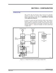
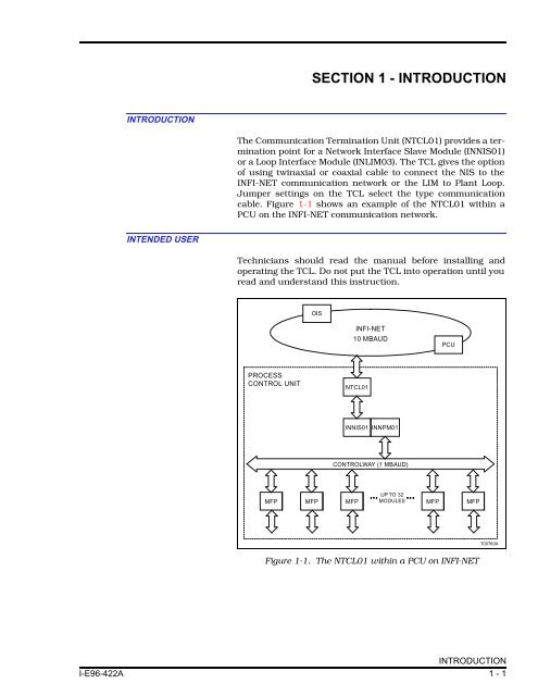
SECTION 1 - INTRODUCTIONINTRODUCTIONThe Communication <strong>Termination</strong> <strong>Unit</strong> (<strong>NTCL01</strong>) provides a terminationpoint for a Network Interface Slave Module (INNIS01)or a Loop Interface Module (INLIM03). The TCL gives the optionof using twinaxial or coaxial cable to connect the NIS to theINFI-NET communication network or the LIM to Plant Loop.Jumper settings on the TCL select the type communicationcable. Figure 1-1 shows an example of the <strong>NTCL01</strong> within aPCU on the INFI-NET communication network.INTENDED USERTechnicians should read the manual before installing andoperating the TCL. Do not put the TCL into operation until youread and understand this instruction.OISINFI-NET10 MBAUDPCUPROCESSCONTROL UNIT<strong>NTCL01</strong>INNIS01 INNPM01CONTROLWAY (1 MBAUD)UP TO 32MFP MFP MFP MODULES MFP MFPT00760AFigure 1-1. The <strong>NTCL01</strong> within a PCU on INFI-NETINTRODUCTIONI-E96-422A 1 - 1
INTRODUCTION®HARDWARE DESCRIPTIONThe TCL attaches to a Field <strong>Termination</strong> Panel (NFTP01), insidethe INFI 90 ® cabinet, with two mounting screws and oneground screw. It is a printed circuit board that consists of:• Terminal strips• BNC connectors• Electronic components• Jumpers• FuseFEATURESThe <strong>NTCL01</strong> provides connectors for both twinaxial cable andcoaxial cable. Jumpers on the circuit board set the impedanceto match the communication cable. The +24 VDC supplied tothe board is fused, protecting the electronic circuitry on board.INSTRUCTION CONTENTThis manual has five sections and two appendices.<strong>Introduction</strong>InstallationMaintenanceRepair/ReplacementProceduresSupport ServicesAppendicesProvides an overview of the TCL.Explains physical installation, wiring and cable requirements,jumper settings, etc.Contains a maintenance schedule.Explains how to replace the fuse or the module.Explains training, documentation and how to order parts fromBailey Controls.Briefly discuss the modules that can use the TCL and provide across-reference of dipswitch and jumper settings for thosemodules.HOW TO USE THIS MANUALRead this manual before installing the TCL. Do the installationsteps in order. Do not operate the TCL until you complete allthe steps in this section. Refer to the appendices for specificmodule and cable questions.® Registered trademark of Elsag Bailey Process Automation.HARDWARE DESCRIPTION1 - 2 I-E96-422A
INTRODUCTIONGLOSSARY OF TERMS AND <strong>ABB</strong>REVIATIONSTermFTPTUCoaxial cableTwinaxial cableDefinitionField <strong>Termination</strong> Panel. A panel inside the INFI 90 cabinet on which to mount terminationunits.<strong>Termination</strong> <strong>Unit</strong>. Provides input/output connection between plant equipment and theINFI 90/Network 90 process modules.A special type of communications cable that can transmit data at high speed.A cable composed of two insulated conductors that are twisted together and attachedor bound with a common covering.NOMENCLATUREHardwareNetwork Interface Slave ModuleLoop Interface ModuleCablesTwinaxial Communication Cable(PVC, lugs at both ends)(non-PVC, lugs at both ends)TCL to INFI-NET Adapter CableCoaxial Communication Cable(PVC, BNC connectors)(non-PVC, BNC connectors)TCL to TCL CableTCL to LIM Cable(PVC)(non-PVC)TCL to NIS Cable(PVC)(non-PVC)Field <strong>Termination</strong> PanelNomenclatureINNIS01INLIM03NKPL01NKPL02NKTL01-3NKCL01NKCL02NKTT01NKLS03NKLS13NKLS01NKLS11NFTP01REFERENCE DOCUMENTSDocument No.I-E96-601I-E96-605DocumentINFI-NET Communications ModulesBus Interface Module/Loop Interface ModuleGLOSSARY OF TERMS AND <strong>ABB</strong>REVIATIONSI-E96-422A 1 - 3
INTRODUCTION®SPECIFICATIONSPower Requirements Voltage 24 VDCCurrent19.7 mA maximum15.8 mA typicalMountingScrew mounts to the field termination panel.Cooling Requirements No cooling necessary when used in Bailey cabinets and operated withinstated environmental limits.Operating Temperature 0 o to 70 o C (32 o to 158 o F).Relative Humidity5% to 90% (± 5%) up to 55 o C (131 o F) noncondensing.5% to 40% (± 5%) up to 70 o C (158 o F) noncondensing.Air QualityBailey equipment should be operated and stored in a noncorrosive environment.CertificationCSA certified as process control equipment for use in an ordinary (nonhazardous)location.Specifications are subject to change without notice.SPECIFICATIONS1 - 4 I-E96-422A