UV Catalog - Blaze Technology Pte Ltd.
UV Catalog - Blaze Technology Pte Ltd.
UV Catalog - Blaze Technology Pte Ltd.

Create successful ePaper yourself
Turn your PDF publications into a flip-book with our unique Google optimized e-Paper software.
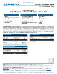
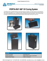
BLAZE TECHNOLOGY PTE LTDIntroductionEIT’s offers a wide selection of <strong>UV</strong> Measurement & ProcessControl Instruments. This guide will help you select the mostappropriate EIT instrument for your application. Detailedproduct Radiometersinformation can be found on the EIT website (www.eit.com) or through our worldwide network of representativesand distributors. Product improvements and specificationsare subject to change.EIT radiometers are intended to measure the process just as the product does, by moving pastthe <strong>UV</strong> sources. These logging radiometers record the total <strong>UV</strong> energy density and/or <strong>UV</strong> peakirradiance. Each radiometer is calibrated to a NIST traceable source.<strong>UV</strong> energy can be generated from different sourcesranging from arc and microwave lamps to pulsed Xenonto LEDs. But regardless of the source, measurementof <strong>UV</strong> comes down to three parameters oftencritical to the process - wavelength, peak irradianceand energy density.Top: Examples of <strong>UV</strong> sourcesLeft: A <strong>UV</strong> source on a robotic arm passing over a dimensionalobject with multiple EIT 3D sensors embedded in the object tomeasure the <strong>UV</strong>Power Puck® II & <strong>UV</strong>ICURE® Plus IIContinuing Education & EIT ProductKnowledgeEIT is committed to education and having users understand <strong>UV</strong> and the fundamentalsof <strong>UV</strong> measurement, <strong>UV</strong> process control and the proper use of our instruments.EIT generates articles and technical papers and frequently speaksworldwide at seminars, conferences and symposiums on <strong>UV</strong> and <strong>UV</strong> measurement.Much of the work that EIT has generated is posted on the EIT website tohelp educate users and potential users.WavelengthThe <strong>UV</strong> spectrum extends from 250 nm to nearly 400 nm. Just as we refer to differentparts of the visible spectrum as red or green, common designations (<strong>UV</strong>A,<strong>UV</strong>B, <strong>UV</strong>C, and <strong>UV</strong>V) are used to describe different bands of the <strong>UV</strong> spectrum.A <strong>UV</strong> source needs to match the chemistry and substrate in your application, andApplications:your measurement instrument needs to measure the bands which are of importanceto• Ideal for all <strong>UV</strong> curing applications including inks, adhesives, coatings and resinsyour process. The shorter bands (<strong>UV</strong>C) do not penetrate as far into acoating • while Establish the the longer optimum <strong>UV</strong> level bands for (<strong>UV</strong>A, curing; <strong>UV</strong>V) then measure have the and ability maintain to this move level further for productioninto a coating. • Available in a Low Power version for measuring 1‐100 mW/cm 2The <strong>UV</strong> spectrum Features: is divided into the <strong>UV</strong>A, <strong>UV</strong>B, <strong>UV</strong>C and <strong>UV</strong>V bands. An EIT Power Puck II (right)can measure the irradiance and energy density in each of these bands simultaneously.• The <strong>UV</strong> Power Puck II measures 4 different <strong>UV</strong> bands simultaneously. The <strong>UV</strong>ICURE Plus IIis a single band instrument (choose <strong>UV</strong>A, <strong>UV</strong>B, <strong>UV</strong>C or <strong>UV</strong>V at time of purchase).• Robust, easy to use with user replaceable AAA batteries• Set up menu allows user to display data screen mode, graph screen mode or reference mode,select units and instrument sample rates• Includes communications package for transferring data to a computerEIT’s representatives and distributors also have extensive experiencewith <strong>UV</strong>, <strong>UV</strong> applications and <strong>UV</strong> measurement and should also beused as a resource to help your understanding.Left to Right: Data Screen Mode, Graph Screen Mode and Reference Mode from <strong>UV</strong> Power Puck® II and <strong>UV</strong>I‐CURE® Plus II screensFor Local Support Singapore 65 6270 2188 Malaysia 604 390 5882 Thailand 66 2361 2926 Email sales@blazeasia.com www.blazeasia.com
BLAZE TECHNOLOGY PTE LTDEIT ResourcesInstrument Services & Technical SupportEIT’s Customer Service / Metrology Laboratory services all EIT <strong>UV</strong> instruments.This includes calibrations, upgrades, warranty and non-warranty repair.With years of experience, our Metrology Lab technicians understand the design,specifications, and tolerances for all of our instruments. Each device is meticulouslycalibrated or repaired according to EIT procedures to ensure repeatableresults and reliable data. A lifetime historical service and calibration record ismaintained and can be accessed for the life of each instrument.All calibrated EIT <strong>UV</strong> instruments have NIST traceability. EIT technicians alsohave access to the specially matched optics and genuine factory components thatare used in our radiometers. Customer Service personnel strive to provide quickturn-around time on all services.EIT has authorized a select number of independent Service Centers throughoutthe world to calibrate EIT instruments under license from EIT. The staff at theseService Centers have completed training at EIT and work closely with our techniciansand engineers to service EIT instruments using procedures, standards andcomponents supplied by EIT.Why Measure <strong>UV</strong>?You cannot establish, maintain, improve or troubleshoot a process without measuringit. EIT provides instruments designed to help manufacturers and suppliersof <strong>UV</strong> chemistry and equipment measure the important parameters of the curingprocess. The right instrument helps you communicate with others about yourprocess and to create a specification that can be understood and reproduced.Irradiance and Energy DensityWhile thermal processes frequently rely on temperature and time, <strong>UV</strong> processesare ordinarily based on irradiance and time. Irradiance may be thought of ashow “bright” a <strong>UV</strong> source is, often determined by the lamp design, optics and thedistance between the source and the target. Irradiance is commonly expressedin terms of Watts per square centimeter(W/cm 2 or mW/cm 2 ) .Energy Density is a measurementof the irradiance over time and isexpressed in terms of Joules persquare centimeter (J/cm 2 or mJ/cm 2 ). One Watt for One second =One Joule. Most <strong>UV</strong> processesrequire a minimum level of both irradianceand energy density.Above: Data collected with an EIT PowerMAP from two different <strong>UV</strong> sources. Irradiance is on the Yaxis and time on the X axis. Irradiance is depicted by the height of the trace while energy density isrepresented by the area under each curve.At EIT headquarters, speciallytrained technicians provide repair,and NIST-traceable calibrationservices for all EIT instruments.About EITFounded in 1977, EIT provides contract electronic manufacturing & engineeringservices, providing electronic assemblies for a variety of medical, industrial, analyticalinstrument and telecommunications customers. Over two hundred EIT employeeswork to support our customers and to design, manufacture, assemble,calibrate, sell, service and support our <strong>UV</strong> measurement products. EIT’s QualityManagement System is ISO 9001 registered and EIT currently operates fromthree facilities in Virginia.Visit www.eit.com to obtain RMA Service FormFor Local Support Singapore 65 6270 2188 Malaysia 604 390 5882 Thailand 66 2361 2926 Email sales@blazeasia.com www.blazeasia.com
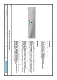
BLAZE TECHNOLOGY PTE LTDInstrument SelectionHow do you select the proper EIT instrument for your application? This checklistcovers a few of the important considerations. More information is availablethrough EIT, our representatives & distributors, as well as on the EIT web site:www.eit.comInstrument Checklist:Size - EIT instruments come in a variety of sizes. Do I have any restrictions in myprocess? If an instrument will not physically fit, do I have room to install an OnlineCompact Sensor?Measurement Process – Will exposure of the instrument involve movement orwill it be a static exposure? How fast is movement? Is the process repeatable?Ease of Use - How easy is it to use and get information from the instrument?Does use of the instrument require a process engineer or can production staff use it?Dynamic Range - Match the dynamic range of the instrument to the <strong>UV</strong> sourceand process.Spectral Bandwidth - Match the bandwidth(s) in the instrument to your process.Multiple band instruments such as the PowerMAP and Power Puck II allow theuser to monitor both the short wave and long wave <strong>UV</strong>. Tracking the <strong>UV</strong> in multiplebands can identify problems such as aging bulbs and reflectors that need cleaningvery quickly. Narrow band instruments such as our EIT instruments provide morespecific information than a single reading found in broad band instruments .Absolute vs. Relative values - How will I use the values obtained from the instrument?Do I need to communicate in absolute (calibrated) values or am I looking forrelative changes over time? Do I need a combination of both calibrated and relativereadings?Communication – Will I be able to share the values obtained from the instrumentwith suppliers and others in the industry and have them communicate with me?Stability, Service & Support - How stable and how much experience does thecompany have that makes the product? Will I be able to get service and supportfrom the manufacturer? Do they have a worldwide network of representatives anddistributors?EIT offers the rightinstrument for everyapplication. Shownare (from left) the EITPowerMAP and PowerViewanalysis software, PALMProbe, online CompactSensors, and MicroCure)Suggested Sensor Locations1. Behind reflector looking at bulb2. Behind reflector looking at bulband reflected energy3. Below reflector angled uptoward bulb and reflectedenergy4. From cure surface looking atbulb and reflector5. From end of lamp housing6. Through quartz plate, filtermaterials or with quartz rod pick up<strong>UV</strong> Intensity Monitor (DIN Rail)Features• Monitors a single <strong>UV</strong> lamp, 0-10V analog outputproportional to <strong>UV</strong>• Designed for PLC feedback with maximum flexibility• User settable alarms & relay contacts• 24V AC/DC power, DIN Rail panel mountable<strong>UV</strong> lamp systems vary in design and installation,The above locations are suggestions only.Online <strong>UV</strong> Intensity DisplayFeatures• Monitors a single <strong>UV</strong> lamp; LED display of lamp’srelative intensity from 0-199%• 0-10V analog output proportional to <strong>UV</strong>• User settable alarms & relay contacts• 24V AC/DC power, panel mount convenienceFor Local Support Singapore 65 6270 2188 Malaysia 604 390 5882 Thailand 66 2361 2926 Email sales@blazeasia.com www.blazeasia.comMultibrite ®Features• Monitors up to 4 <strong>UV</strong> lamps simultaneously• LED display of lamps’ relative intensity from0-199%• Adjustable audible and visible alarms; externalalarm outputs• 4-20 mA and 0-10V analog output proportionalto <strong>UV</strong> on each channel
BLAZE TECHNOLOGY PTE LTDOnline <strong>UV</strong> Measurement SystemsEIT Online Monitoring Systems provide continuous monitoring of <strong>UV</strong> lamp intensity.Online Monitoring Systems are used in:• Processes where a radiometer will not fit or it is difficult to easily reach the<strong>UV</strong> source• High speed or high product value applications where a tremendous amountof expensive scrap can be generated before a problem might ordinarily bedetected• Applications where the process window is narrow and requires closeattention• As a complement to radiometers to correlate absolute to relative readings• Applications requiring full-time monitoring to generate quality, conformanceor compliance documentationThere are two basic building blocks to continuous monitoring; a Compact Sensorand a means to display real-time data. EIT offers a number of Compact Sensorand display options. Results are presented as a percentage of the original output,usually set to 100% when the lamp is new.Compact SensorThe key to the success of EIT’s Online Monitoring Systems is the durable, longlasting Compact Sensor. Features include:• High resistance to solarization (degradation)• Compact profile for installation in tight spaces• Square body design for easy mounting• Optional port for air/nitrogen purge to keep thesensor clean and cool• Sealed optics to prevent fouling• Signal provided that is proportional to the <strong>UV</strong>intensity• Choice of several bandwidths to fit application• Multiple Mounting optionsThe small Compact Sensor isrobust, and provides accuratereal-time lamp monitoring.Product Selection ChartHow do you select the proper EIT instrument for your application? This checklistcovers a few of the important considerations. More information is availablethrough EIT, our representatives & distributors, as well as on the EIT web site:www.eit.comFeaturesProductEnergy Density Reading • • • • • • • •Peak Irradiance Reading • • • • • • • •Relative Intensity Reading•High Intensity Applications • • • • • • • • • •Low Intensity Applications • • • • • • •Download to PC • • • • •Single Band • • • • • • •Multiple Band (4) • • • •Exposure/Plate Making• (LP) • (LP)Spot-curing Applications•Small Batch Curing • • • •Web Press Application • •Small Container Curing • • •Dimensional Objects (3D) • •Inkjet • • • • • • •Pulsed Xenon Sources•LED • • • •<strong>UV</strong> Bandwidth Choices:EIT offers instruments in the following bandwidths :Examples of Compact Sensor Mounting Locations Left to Right: Mounted behind the reflectorlooking at bulb, mounted behind reflector looking at reflected <strong>UV</strong>, mounted near cure surface andusing quartz rod to pick up <strong>UV</strong>• <strong>UV</strong>C: 250-260nm• <strong>UV</strong>B: 280-320 nm• <strong>UV</strong>A: 320-390nm• <strong>UV</strong>A2: 380-410nm• <strong>UV</strong>V: 395-445nmContact EIT for current offeringsFor Local Support Singapore 65 6270 2188 Malaysia 604 390 5882 Thailand 66 2361 2926 Email sales@blazeasia.com www.blazeasia.com
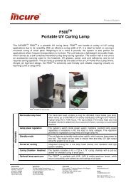
BLAZE TECHNOLOGY PTE LTDRadiometersPALM Probe ® (Production Ambient Light Measurement)Applications• Use to measure system performance in applications where space is limited or the<strong>UV</strong> source is difficult to access (such as label, web & converting applications)• Establish and maintain a <strong>UV</strong> process window, coordinate readings from online sensorsand online displays• Measure irradiance in production (high level) and stray hazard (low level) environmentsFeatures• Measure and display peak irradiance, energy density and exposure time• Wide dynamic range, auto-ranging and zeroing• Electrically isolated and insulated probe. Contains no fiber which can break• Locator kits for exact positioning are availablePowerView ® SoftwarePowerView® Software allows you to view, analyze, manipulate, store and sharedata collected with the <strong>UV</strong> PowerMAP® and <strong>UV</strong> Map Plus TM Systems. Some examplesof actual data collected with the instruments are shown below. Irradiance(W/cm 2 ) is shown on the Y-axis and time on the X-axis (seconds). Energy Density(J/cm 2 ) values are provided on the DataView screen.PowerView® GraphViewscreen showing the samesingle lamp in focused (red)and non focused (blue)positionsPowerView® GraphView screen showingtwo different lamp types. <strong>UV</strong>A is shown inblue and <strong>UV</strong>V in red. Note the differencesbetween the two . The first lamp is amercury-gallium additive (V) bulb and thesecond lamp is a mercury (Hg) bulbSpot Cure ®Applications• Monitor spot curing system performance• Measure light guide degradation• Determine optimum positioning of light guide• Compare spot cure systemsRight: PowerView® GraphView screenshowing wide differences in the <strong>UV</strong>Aoutput on a multi-lamp (six) line. Lampthree is out of focus; other lamps vary inirradiance values.Below: DataView screen below showsactual energy density (J/cm 2 ) andpeak power density values (W/cm 2 )Features• Measures <strong>UV</strong> irradiance• Small size 6.4”L x 1.74” diameter• Easy to use, extremely long battery life(100,000 measurements)• Adaptors support different size light guidesand allow repeatable measurementsFor Local Support Singapore 65 6270 2188 Malaysia 604 390 5882 Thailand 66 2361 2926 Email sales@blazeasia.com www.blazeasia.com
BLAZE TECHNOLOGY PTE LTDRadiometersEIT radiometers are intended to measure the process just as the product does,by moving past the <strong>UV</strong> sources. These logging radiometers record the total <strong>UV</strong>energy density and/or <strong>UV</strong> peak irradiance. Each radiometer is calibrated to aNIST traceable source.Power Puck ® II & <strong>UV</strong>ICURE ® Plus IIPower Puck ® FLASHEIT’s Power Puck® FLASH is a four channel instrumentthat was developed specifically for rapidly-pulsed <strong>UV</strong>sources with a frequency of 100-120 times per second.The ideal instrument for short duration, high intensitysources. Contact EIT for more information.MicroCure ®Applications:• Use in applications that cannot be accessed by EIT’s puck-size radiometers includingsmall piece, small conveyor, exposure systems, batch applications and smalldimensional objects• Use to establish <strong>UV</strong> curing levels and monitor <strong>UV</strong> lamp performance• Available in 2W and 10W versionsApplications:• Ideal for all <strong>UV</strong> curing applications including inks, adhesives, coatings and resins• Establish the optimum level for curing; then measure and maintain this level forproduction• Available in:Standard Version–100mW-10W/cm 2 ; <strong>UV</strong>C 10mW-1W/cm 2Mid Range Version–10mW-1W/cm 2 ; <strong>UV</strong>C 1mW-100mW/cm 2Low Power Range–1mW-100mW/cm 2Features:• The <strong>UV</strong> Power Puck II measures 4 different <strong>UV</strong> bands simultaneously. The<strong>UV</strong>ICURE Plus II is a single band instrument (choose <strong>UV</strong>A, <strong>UV</strong>B, <strong>UV</strong>C or <strong>UV</strong>V attime of purchase).The <strong>UV</strong>A2 Power Puck II version for capturing LED sources in the 380-410 nmrange is configured: <strong>UV</strong>A, <strong>UV</strong>A2, <strong>UV</strong>B & <strong>UV</strong>V.• Robust, easy to use with user replaceable AAA batteries• Set up menu allows user to display data screen mode, graph screen mode orreference mode, select units and instrument sample rates• Includes communications package for transferring data to a computerFeatures:• Miniature radiometer: 1.3”L x 0.95” H x 0.25”T (33.00 mm x 24.13 mm x 6.35 mm)• High sampling rate of 2000 samples per second• MicroCure® is exposed to <strong>UV</strong> and inserted into the battery powered DataReaderto display peak irradiance and energy density values.The compact MicroCure data collection unitLeft to Right: Data Screen Mode, Graph Screen Mode and Reference Mode from <strong>UV</strong> Power Puck®II and <strong>UV</strong>ICURE® Plus II screensThe battery operated MicroCure Data Readerprovides a simple, easy to operate userinterface.For Local Support Singapore 65 6270 2188 Malaysia 604 390 5882 Thailand 66 2361 2926 Email sales@blazeasia.com www.blazeasia.com