
Create successful ePaper yourself
Turn your PDF publications into a flip-book with our unique Google optimized e-Paper software.
<strong>PROsine</strong> <strong>2.0</strong><strong>Inverter</strong>/<strong>Charger</strong>User’s Manual
<strong>PROsine</strong> <strong>2.0</strong> <strong>Inverter</strong>/<strong>Charger</strong>User’s Manual
About <strong>Xantrex</strong><strong>Xantrex</strong> Technology Inc. is a world-leading supplier of advanced power electronics and controls with products from50 watt mobile units to one MW utility-scale systems for wind, solar, batteries, fuel cells, microturbines, and backuppower applications in both grid-connected and stand-alone systems. <strong>Xantrex</strong> products include inverters, batterychargers, programmable power supplies, and variable speed drives that convert, supply, control, clean, and distributeelectrical power.Trademarks<strong>PROsine</strong> <strong>2.0</strong> <strong>Inverter</strong>/<strong>Charger</strong> is a trademark of <strong>Xantrex</strong> International. <strong>Xantrex</strong> is a registered trademark of <strong>Xantrex</strong>International.Other trademarks, registered trademarks, and product names are the property of their respective owners and are usedherein for identification purposes only.Notice of Copyright<strong>PROsine</strong> <strong>2.0</strong> <strong>Inverter</strong>/<strong>Charger</strong> User’s Manual © November 2006 <strong>Xantrex</strong> International. All rights reserved.Exclusion for DocumentationUNLESS SPECIFICALLY AGREED TO IN WRITING, XANTREX TECHNOLOGY INC. (“XANTREX”)(a) MAKES NO WARRANTY AS TO THE ACCURACY, SUFFICIENCY OR SUITABILITY OF ANYTECHNICAL OR OTHER INFORMATION PROVIDED IN ITS MANUALS OR OTHER DOCUMENTATION.(b) ASSUMES NO RESPONSIBILITY OR LIABILITY FOR LOSSES, DAMAGES, COSTS OR EXPENSES,WHETHER SPECIAL, DIRECT, INDIRECT, CONSEQUENTIAL OR INCIDENTAL, WHICH MIGHT ARISEOUT OF THE USE OF SUCH INFORMATION. THE USE OF ANY SUCH INFORMATION WILL BEENTIRELY AT THE USER’S RISK; AND(c) REMINDS YOU THAT IF THIS MANUAL IS IN ANY LANGUAGE OTHER THAN ENGLISH,ALTHOUGH STEPS HAVE BEEN TAKEN TO MAINTAIN THE ACCURACY OF THE TRANSLATION, THEACCURACY CANNOT BE GUARANTEED. APPROVED XANTRES CONTENT IS CONTAINED WITH THEENGLISH LANGUAGE VERSION WHICH IS POSTED AT WWW.XANTREX.COM.Date and RevisionNovember 2006 Revision CPart Number445-0089-01-01Product Number805-2000, 805-2020Contact InformationTelephone: 1 800 670 0707 (toll free North America)1 360 925 5097 (direct)Fax: 1 800 994 7828 (toll free North America)1 360 925 5143 (direct)Email: customerservice@xantrex.comWeb: www.xantrex.com
About This ManualPurposeScopeAudienceOrganizationThe purpose of this User’s Manual is to provide explanations and procedures forinstalling, operating, maintaining, and troubleshooting the <strong>PROsine</strong> <strong>2.0</strong> <strong>Inverter</strong>/<strong>Charger</strong>.The Manual provides safety guidelines, detailed planning and setup information,procedures for installing the inverter, as well as information about operating andtroubleshooting the unit. It does not provide details about particular brands ofbatteries. You need to consult individual battery manufacturers for thisinformation.The Manual is intended for anyone who needs to install and operate the <strong>PROsine</strong><strong>2.0</strong> <strong>Inverter</strong>/<strong>Charger</strong>. Installers should be certified technicians or electricians.This Manual is organized into seven chapters and three appendixes:Introduction: Chapter 1 introduces you to the <strong>PROsine</strong>, explains the inverting,changing and power system management functionsProduct Orientation: Chapter 2 will familiarize you with the followingcomponents of a <strong>PROsine</strong> system:Installation: Chapter 3 This section gives complete information for installing a<strong>PROsine</strong> system.Configuration: Chapter 4 explains how to configure the <strong>PROsine</strong> to best meetyour electrical system requirements. It is divided into three parts:Operation: Chapter 5 begins with a system startup check that you carry out afterinstallation and configuration to verify that the <strong>PROsine</strong> is operating correctly.The chapter also provides information that will guide you during routine, ongoingoperations.Troubleshooting: Chapter 6 describes how to troubleshoot the <strong>PROsine</strong>Series Operation: Chapter 7 provides information about installing and operatingtwo <strong>PROsine</strong>s in series:445-0089-01-01 iii
About This ManualSpecifications: Appendix A contains specifications and performance graphs forthe <strong>PROsine</strong> and the display panel.System Diagrams: Appendix B illustrates typical designs for <strong>PROsine</strong> customdesignedsystems.Charging Algorithms: Appendix C provides information about the chargingalgorithms for <strong>PROsine</strong> <strong>2.0</strong>.iv 445-0089-01-01
About This ManualConventions UsedThe following conventions are used in this guide.WARNINGWarnings identify conditions or practices that could result in personal injury or loss of lifeCAUTIONCautions identify conditions or practices that could result in damage to the unit or otherequipment.Abbreviations and AcronymsRelated DocumentsRelated InformationImportant: These notes describe things which are important for you to know, but not asserious as a caution or warning.<strong>PROsine</strong> <strong>2.0</strong> <strong>Inverter</strong>/<strong>Charger</strong> Quick Installation GuidePart Number: 445-0099-01-01: This document is included with your <strong>PROsine</strong>. Itis a job aid that provides instructions for installing the <strong>PROsine</strong> and its displaypanel. It also provides a mounting template for the <strong>PROsine</strong>.<strong>PROsine</strong> <strong>2.0</strong> <strong>Inverter</strong>/<strong>Charger</strong> Display Panel Mounting TemplatePart Number: 445-0101-01-01: This is provided with your <strong>PROsine</strong>.<strong>PROsine</strong> <strong>2.0</strong> <strong>Inverter</strong>/<strong>Charger</strong> Quick Reference GuidePart Number: 445-0100-01-01: This document is included with your <strong>PROsine</strong>. Itprovides frequently used information about configuring and operating the unit aswell as system default values.You can find more information about <strong>Xantrex</strong> Technology Inc. as well as itsproducts and services at www.xantrex.com445-0089-01-01 v
Important Safety InstructionsWARNINGThis chapter contains important safety and operating instructions. Read and keep thisUser’s Manual for future reference.WARNING:Limitations on useThe <strong>PROsine</strong> <strong>2.0</strong> <strong>Inverter</strong>/<strong>Charger</strong> is not intended for use in connection with life supportsystems or other medical equipment or devices.1. Before installing and using the <strong>PROsine</strong> <strong>2.0</strong> <strong>Inverter</strong>/<strong>Charger</strong> (<strong>PROsine</strong>), readall instructions and cautionary markings on the <strong>PROsine</strong>, the batteries, and allappropriate sections of this Manual.2. Do not expose the <strong>PROsine</strong> to rain, snow, spray, or bilge water. To reduce riskof fire hazard, do not cover or obstruct the ventilation openings. Do not installthe <strong>PROsine</strong> in a zero-clearance compartment. Overheating may result.3. Use only attachments recommended or sold by the manufacturer. Doingotherwise may result in a risk of fire, electric shock, or injury to persons.4. The <strong>PROsine</strong> is designed to be permanently connected to you AC and DCelectrical systems. <strong>Xantrex</strong> recommends that all wiring be done by a certifiedtechnician or electrician to ensure adherence to proper electrical wiringregulations.5. To avoid a risk of fire and electric shock, make sure that existing wiring is ingood condition and that wire is not undersized. Do not operate the <strong>PROsine</strong>with damaged or substandard wiring.6. Do not operate the <strong>PROsine</strong> if it has received a sharp blow, been dropped, orotherwise damaged in any way. If the <strong>PROsine</strong> is damaged, see the Warrantysection.7. Do not disassemble the <strong>PROsine</strong>. It contains no user-serviceable parts. See theWarranty section for instructions on obtaining service. Attempting to servicethe <strong>PROsine</strong> yourself may result in a risk of electrical shock or fire. Internalcapacitors remain charged after all power is disconnected.8. To reduce the risk of electrical shock, disconnect both AC and DC powerfrom the <strong>PROsine</strong> before attempting any maintenance or cleaning or workingon any circuits connected to the <strong>PROsine</strong>. Turning off controls will not reducethis risk.9. The <strong>PROsine</strong> must be provided with an equipment-grounding conductorconnected to the AC input ground terminal. Grounding and all other wiringmust comply with local codes and ordinances.445-0089-01-01 vii
SafetyExplosive gas precautionsWARNING: Explosion hazard1. Working in the vicinity of lead-acid batteries is dangerous. Batteries generateexplosive gases during normal operation. Therefore, you must read this guideand follow the instructions exactly before installing or using your <strong>PROsine</strong>.2. This equipment contains components which tend to produce arcs or sparks. Toprevent fire or explosion, do not install the <strong>PROsine</strong> in compartmentscontaining batteries or flammable materials, or in locations that requireignition-protected equipment. This includes any space containing gasolinepoweredmachinery, fuel tanks, as well as joints, fittings, or other connectionsbetween components of the fuel system.3. To reduce the risk of battery explosion, follow these instructions and thosepublished by the battery manufacturer and the manufacturer of the equipmentin which the battery is installed.Precautions When Working With BatteriesWARNING: Explosion or fire hazard1. Follow all instructions published by the battery manufacturer and themanufacturer of the equipment in which the battery is installed.2. Make sure the area around the battery is well ventilated.3. Never smoke or allow a spark or flame near the engine or batteries.4. Use caution to reduce the risk or dropping a metal tool on the battery. It couldspark or short circuit the battery or other electrical parts and could cause anexplosion.5. Remove all metal items, like rings, bracelets, and watches when working withlead-acid batteries. Lead-acid batteries produce a short circuit current highenough to weld metal to skin, causing a severe burn.6. Have someone within range of your voice or close enough to come to your aidwhen you work near a lead-acid battery.7. Have plenty of fresh water and soap nearby in case battery acid contacts skin,clothing, or eyes.8. Wear complete eye protection and clothing protection. Avoid touching youreyes while working near batteries.viii 445-0089-01-01
Safety9. If battery acid contacts skin or clothing, wash immediately with soap andwater. If acid enters your eye, immediately flood it with running cold waterfor at least twenty minutes and get medical attention immediately.10. If you need to remove a battery, always remove the ground terminal from thebattery first. Make sure all accessories are off so you don’t cause a spark.445-0089-01-01 ix
ContentsImportant Safety Instructions - - - - - - - - - - - - - - - - - - - - - - - - - - - - - - - - - - - - - - - - - - -vii1 IntroductionYour <strong>PROsine</strong>- - - - - - - - - - - - - - - - - - - - - - - - - - - - - - - - - - - - - - - - - - - - - - - - - - - - - - - - - 1–2The Heart of a Sophisticated, Independent Power System - - - - - - - - - - - - - - - - - - - - - - - - - - - 1–3Inverting - - - - - - - - - - - - - - - - - - - - - - - - - - - - - - - - - - - - - - - - - - - - - - - - - - - - - - - - - - 1–3Charging - - - - - - - - - - - - - - - - - - - - - - - - - - - - - - - - - - - - - - - - - - - - - - - - - - - - - - - - - - 1–4Power System Management - - - - - - - - - - - - - - - - - - - - - - - - - - - - - - - - - - - - - - - - - - - - - 1–5Materials List - - - - - - - - - - - - - - - - - - - - - - - - - - - - - - - - - - - - - - - - - - - - - - - - - - - - - - - - - 1–6Default Values for the <strong>PROsine</strong> System - - - - - - - - - - - - - - - - - - - - - - - - - - - - - - - - - - - - - - - 1–92 Product Orientation<strong>PROsine</strong> Features - - - - - - - - - - - - - - - - - - - - - - - - - - - - - - - - - - - - - - - - - - - - - - - - - - - - - - 2–2AC End - - - - - - - - - - - - - - - - - - - - - - - - - - - - - - - - - - - - - - - - - - - - - - - - - - - - - - - - - - 2–2AC Panel Options - - - - - - - - - - - - - - - - - - - - - - - - - - - - - - - - - - - - - - - - - - - - - - - - - - - 2–3DC End - - - - - - - - - - - - - - - - - - - - - - - - - - - - - - - - - - - - - - - - - - - - - - - - - - - - - - - - - - 2–4DC Terminal Covers - - - - - - - - - - - - - - - - - - - - - - - - - - - - - - - - - - - - - - - - - - - - - - - 2–5Display Panel Features - - - - - - - - - - - - - - - - - - - - - - - - - - - - - - - - - - - - - - - - - - - - - - - - - - - 2–6DISPLAY Mode Switch - - - - - - - - - - - - - - - - - - - - - - - - - - - - - - - - - - - - - - - - - - - - 2–7INVERTER Switch - - - - - - - - - - - - - - - - - - - - - - - - - - - - - - - - - - - - - - - - - - - - - - - 2–8INVERTER LEDs - - - - - - - - - - - - - - - - - - - - - - - - - - - - - - - - - - - - - - - - - - - - - - - - 2–8CHARGER Switch - - - - - - - - - - - - - - - - - - - - - - - - - - - - - - - - - - - - - - - - - - - - - - - - 2–9CHARGER LEDs - - - - - - - - - - - - - - - - - - - - - - - - - - - - - - - - - - - - - - - - - - - - - - - - - 2–9LCD Panel - - - - - - - - - - - - - - - - - - - - - - - - - - - - - - - - - - - - - - - - - - - - - - - - - - - - 2–10Data Display Mode - - - - - - - - - - - - - - - - - - - - - - - - - - - - - - - - - - - - - - - - - - - - - - - 2–10Configuration Mode - - - - - - - - - - - - - - - - - - - - - - - - - - - - - - - - - - - - - - - - - - - - - - 2–10Menu Navigation and Data Selection Buttons - - - - - - - - - - - - - - - - - - - - - - - - - - - - - 2–11Battery Temperature Sensor - - - - - - - - - - - - - - - - - - - - - - - - - - - - - - - - - - - - - - - - - - - - - - 2–123 InstallationSafety Instructions - - - - - - - - - - - - - - - - - - - - - - - - - - - - - - - - - - - - - - - - - - - - - - - - - - - - - - 3–2Installation Codes - - - - - - - - - - - - - - - - - - - - - - - - - - - - - - - - - - - - - - - - - - - - - - - - - - - - 3–2Installation Tools and Materials - - - - - - - - - - - - - - - - - - - - - - - - - - - - - - - - - - - - - - - - - - 3–3Installation Procedures - - - - - - - - - - - - - - - - - - - - - - - - - - - - - - - - - - - - - - - - - - - - - - - - 3–3Step 1: Designing the Installation- - - - - - - - - - - - - - - - - - - - - - - - - - - - - - - - - - - - - - - - - - - - 3–4Step 2: Choosing a Location for the <strong>PROsine</strong>- - - - - - - - - - - - - - - - - - - - - - - - - - - - - - - - - - - - 3–9Step 3: Mounting the <strong>PROsine</strong>- - - - - - - - - - - - - - - - - - - - - - - - - - - - - - - - - - - - - - - - - - - - - 3–10445-0089-01-01 xi
ContentsStep 4: Connecting the AC Input Wires - - - - - - - - - - - - - - - - - - - - - - - - - - - - - - - - - - - - - - -3–11General AC Wiring Considerations - - - - - - - - - - - - - - - - - - - - - - - - - - - - - - - - - - - - - - -3–11AC Input Connections - - - - - - - - - - - - - - - - - - - - - - - - - - - - - - - - - - - - - - - - - - - - -3–12Step 5: Configuring the Output Neutral Bonding System - - - - - - - - - - - - - - - - - - - - - - - - - - -3–13AC Output Neutral-to-Ground Bonding System - - - - - - - - - - - - - - - - - - - - - - - - - - - -3–13Step 6: Connecting the AC Output Wires - - - - - - - - - - - - - - - - - - - - - - - - - - - - - - - - - - - - - -3–15Connections for Hardwire Option - - - - - - - - - - - - - - - - - - - - - - - - - - - - - - - - - - - - - - - -3–15Connections for Single Hardwire Output With GFCI - - - - - - - - - - - - - - - - - - - - - - - - - - -3–16Step 7: Connecting the DC Cables- - - - - - - - - - - - - - - - - - - - - - - - - - - - - - - - - - - - - - - - - - -3–17DC Grounding - - - - - - - - - - - - - - - - - - - - - - - - - - - - - - - - - - - - - - - - - - - - - - - - - -3–19Step 8: Mounting the Display Panel- - - - - - - - - - - - - - - - - - - - - - - - - - - - - - - - - - - - - - - - - -3–20Step 9: Connecting the Battery Temperature Sensor- - - - - - - - - - - - - - - - - - - - - - - - - - - - - - -3–21Mounting Options - - - - - - - - - - - - - - - - - - - - - - - - - - - - - - - - - - - - - - - - - - - - - - - -3–21Mounting to the Negative Battery Terminal - - - - - - - - - - - - - - - - - - - - - - - - - - - - - - -3–21Mounting to the Side of the Battery Case - - - - - - - - - - - - - - - - - - - - - - - - - - - - - - - -3–23Step 10: Connecting the Remote Shutdown - - - - - - - - - - - - - - - - - - - - - - - - - - - - - - - - - - - -3–24Installation Steps - - - - - - - - - - - - - - - - - - - - - - - - - - - - - - - - - - - - - - - - - - - - - - - - -3–24Next Steps - - - - - - - - - - - - - - - - - - - - - - - - - - - - - - - - - - - - - - - - - - - - - - - - - - - - - - - -3–254 ConfigurationPart 1: General Configuration Information - - - - - - - - - - - - - - - - - - - - - - - - - - - - - - - - - - - - - 4–2Entering Configure Mode - - - - - - - - - - - - - - - - - - - - - - - - - - - - - - - - - - - - - - - - - - - - - - 4–2Entering Installer-Only Mode - - - - - - - - - - - - - - - - - - - - - - - - - - - - - - - - - - - - - - - - - - - 4–2Changing Settings - - - - - - - - - - - - - - - - - - - - - - - - - - - - - - - - - - - - - - - - - - - - - - - - 4–3Resetting to Factory Defaults - - - - - - - - - - - - - - - - - - - - - - - - - - - - - - - - - - - - - - - - - - - 4–4Part 2: Configuration Menus and Screens - - - - - - - - - - - - - - - - - - - - - - - - - - - - - - - - - - - - - - 4–4Part 3: Configuration Options- - - - - - - - - - - - - - - - - - - - - - - - - - - - - - - - - - - - - - - - - - - - - - 4–6Clear Errors in <strong>PROsine</strong> - - - - - - - - - - - - - - - - - - - - - - - - - - - - - - - - - - - - - - - - - - - - - - - 4–6Configure <strong>PROsine</strong>—Basic Menu - - - - - - - - - - - - - - - - - - - - - - - - - - - - - - - - - - - - - - - - 4–7Menu Choices or Information Displayed - - - - - - - - - - - - - - - - - - - - - - - - - - - - - - - - - 4–7Configure <strong>PROsine</strong>—Advanced Menu - - - - - - - - - - - - - - - - - - - - - - - - - - - - - - - - - - - - - 4–8Menu Choices or Information Displayed - - - - - - - - - - - - - - - - - - - - - - - - - - - - - - - - - 4–8Configure Display Panel Menu - - - - - - - - - - - - - - - - - - - - - - - - - - - - - - - - - - - - - - - - - -4–11Menu Choices or Information Displayed - - - - - - - - - - - - - - - - - - - - - - - - - - - - - - - - -4–11Configure Battery Menu - - - - - - - - - - - - - - - - - - - - - - - - - - - - - - - - - - - - - - - - - - - - - - -4–12Menu Choices or Information Displayed - - - - - - - - - - - - - - - - - - - - - - - - - - - - - - - - -4–13Diagnostics Menu - - - - - - - - - - - - - - - - - - - - - - - - - - - - - - - - - - - - - - - - - - - - - - - - - - -4–17Menu Choices or Information Displayed - - - - - - - - - - - - - - - - - - - - - - - - - - - - - - - - -4–17Next Steps - - - - - - - - - - - - - - - - - - - - - - - - - - - - - - - - - - - - - - - - - - - - - - - - - - - - - - - -4–18xii 445-0089-01-01
5 OperationContentsPart 1: System Startup Check - - - - - - - - - - - - - - - - - - - - - - - - - - - - - - - - - - - - - - - - - - - - - - 5–2Part 2: Operating Considerations - - - - - - - - - - - - - - - - - - - - - - - - - - - - - - - - - - - - - - - - - - - - 5–3Fan Operation - - - - - - - - - - - - - - - - - - - - - - - - - - - - - - - - - - - - - - - - - - - - - - - - - - - - - - 5–3ON/OFF/REMote Control of <strong>PROsine</strong> Operation - - - - - - - - - - - - - - - - - - - - - - - - - - - - - - 5–3Hysteresis - - - - - - - - - - - - - - - - - - - - - - - - - - - - - - - - - - - - - - - - - - - - - - - - - - - - - - - - - 5–3Part 3: Operation in <strong>Inverter</strong> Mode - - - - - - - - - - - - - - - - - - - - - - - - - - - - - - - - - - - - - - - - - - - 5–5Load Sensing Mode - - - - - - - - - - - - - - - - - - - - - - - - - - - - - - - - - - - - - - - - - - - - - - - - - - 5–5Operating Limits for <strong>Inverter</strong> Operation - - - - - - - - - - - - - - - - - - - - - - - - - - - - - - - - - - - - - 5–5Power Output - - - - - - - - - - - - - - - - - - - - - - - - - - - - - - - - - - - - - - - - - - - - - - - - - - - - 5–5Input Voltage - - - - - - - - - - - - - - - - - - - - - - - - - - - - - - - - - - - - - - - - - - - - - - - - - - - - 5–6Part 4: Operation in <strong>Charger</strong> Mode- - - - - - - - - - - - - - - - - - - - - - - - - - - - - - - - - - - - - - - - - - - 5–7Operation in Equalization Mode - - - - - - - - - - - - - - - - - - - - - - - - - - - - - - - - - - - - - - - - - - 5–7Equalization Procedure - - - - - - - - - - - - - - - - - - - - - - - - - - - - - - - - - - - - - - - - - - - - - 5–8Operating Limits for <strong>Charger</strong> Operation - - - - - - - - - - - - - - - - - - - - - - - - - - - - - - - - - - - - - 5–9Power Share - - - - - - - - - - - - - - - - - - - - - - - - - - - - - - - - - - - - - - - - - - - - - - - - - - - - - - - 5–9Part 5: Display Mode Screens - - - - - - - - - - - - - - - - - - - - - - - - - - - - - - - - - - - - - - - - - - - - - 5–106 TroubleshootingGeneral Troubleshooting Guidelines- - - - - - - - - - - - - - - - - - - - - - - - - - - - - - - - - - - - - - - - - - 6–2Shutdown / Restart Without Error Message - - - - - - - - - - - - - - - - - - - - - - - - - - - - - - - - - - 6–3Resetting <strong>PROsine</strong> Operation - - - - - - - - - - - - - - - - - - - - - - - - - - - - - - - - - - - - - - - - - - - - 6–3AC Bad Causes - - - - - - - - - - - - - - - - - - - - - - - - - - - - - - - - - - - - - - - - - - - - - - - - - - - - - 6–3Warning Messages- - - - - - - - - - - - - - - - - - - - - - - - - - - - - - - - - - - - - - - - - - - - - - - - - - - - - - 6–4Error Messages - - - - - - - - - - - - - - - - - - - - - - - - - - - - - - - - - - - - - - - - - - - - - - - - - - - - - - - - 6–6Display Panel Faults - - - - - - - - - - - - - - - - - - - - - - - - - - - - - - - - - - - - - - - - - - - - - - - - - - - - 6–9Unexplained Faults - - - - - - - - - - - - - - - - - - - - - - - - - - - - - - - - - - - - - - - - - - - - - - - - - - - - 6–10<strong>Inverter</strong> Applications - - - - - - - - - - - - - - - - - - - - - - - - - - - - - - - - - - - - - - - - - - - - - - - - - - - 6–11Resistive Loads - - - - - - - - - - - - - - - - - - - - - - - - - - - - - - - - - - - - - - - - - - - - - - - - - - - - 6–11Motor Loads - - - - - - - - - - - - - - - - - - - - - - - - - - - - - - - - - - - - - - - - - - - - - - - - - - - - - - 6–11Long Transfer Times - - - - - - - - - - - - - - - - - - - - - - - - - - - - - - - - - - - - - - - - - - - - - - - - 6–11Problem Loads - - - - - - - - - - - - - - - - - - - - - - - - - - - - - - - - - - - - - - - - - - - - - - - - - - - - - 6–127 Series OperationDesigning a Series System - - - - - - - - - - - - - - - - - - - - - - - - - - - - - - - - - - - - - - - - - - - - - - - - 7–2System Overview - - - - - - - - - - - - - - - - - - - - - - - - - - - - - - - - - - - - - - - - - - - - - - - - - 7–2System Components - - - - - - - - - - - - - - - - - - - - - - - - - - - - - - - - - - - - - - - - - - - - - - - 7–2AC Input - - - - - - - - - - - - - - - - - - - - - - - - - - - - - - - - - - - - - - - - - - - - - - - - - - - - - - - 7–4AC Output - - - - - - - - - - - - - - - - - - - - - - - - - - - - - - - - - - - - - - - - - - - - - - - - - - - - - - 7–4Battery Disconnect and Over-Current Protection Requirements - - - - - - - - - - - - - - - - - - 7–4Series Sync Connection - - - - - - - - - - - - - - - - - - - - - - - - - - - - - - - - - - - - - - - - - - - - - 7–4445-0089-01-01 xiii
ContentsInstalling a Series System - - - - - - - - - - - - - - - - - - - - - - - - - - - - - - - - - - - - - - - - - - - - - - - - 7–5Connecting AC Input Wiring - - - - - - - - - - - - - - - - - - - - - - - - - - - - - - - - - - - - - - - - - 7–5Connecting AC Output Wiring - - - - - - - - - - - - - - - - - - - - - - - - - - - - - - - - - - - - - - - 7–6Configuring the <strong>Inverter</strong> Output Neutral Bonding - - - - - - - - - - - - - - - - - - - - - - - - - - - 7–6Connecting the DC Cables - - - - - - - - - - - - - - - - - - - - - - - - - - - - - - - - - - - - - - - - - - 7–6Connecting the DC Ground - - - - - - - - - - - - - - - - - - - - - - - - - - - - - - - - - - - - - - - - - - 7–7Installing the Display Panels - - - - - - - - - - - - - - - - - - - - - - - - - - - - - - - - - - - - - - - - - 7–7Installing the Battery Temperature Sensors - - - - - - - - - - - - - - - - - - - - - - - - - - - - - - - 7–7Installing the Series Sync Cable - - - - - - - - - - - - - - - - - - - - - - - - - - - - - - - - - - - - - - - 7–8Configuring a Series System - - - - - - - - - - - - - - - - - - - - - - - - - - - - - - - - - - - - - - - - - - - - - - 7–9Series System Startup Test- - - - - - - - - - - - - - - - - - - - - - - - - - - - - - - - - - - - - - - - - - - - - - - -7–10Series System Operation - - - - - - - - - - - - - - - - - - - - - - - - - - - - - - - - - - - - - - - - - - - - - - - - -7–11Invert Mode - - - - - - - - - - - - - - - - - - - - - - - - - - - - - - - - - - - - - - - - - - - - - - - - - - - -7–11Charge Mode - - - - - - - - - - - - - - - - - - - - - - - - - - - - - - - - - - - - - - - - - - - - - - - - - - -7–11ABCSpecificationsElectrical Specifications: Invert Mode - - - - - - - - - - - - - - - - - - - - - - - - - - - - - - - - - - - - - - - - A–2Electrical Specifications: Charge Mode - - - - - - - - - - - - - - - - - - - - - - - - - - - - - - - - - - - - - - - A–3Environmental Specifications - - - - - - - - - - - - - - - - - - - - - - - - - - - - - - - - - - - - - - - - - - - - - - A–4System - - - - - - - - - - - - - - - - - - - - - - - - - - - - - - - - - - - - - - - - - - - - - - - - - - - - - - - - - - - - - A–4Regulatory Approvals - - - - - - - - - - - - - - - - - - - - - - - - - - - - - - - - - - - - - - - - - - - - - - - - - - - A–4<strong>Inverter</strong> Overload Operation- - - - - - - - - - - - - - - - - - - - - - - - - - - - - - - - - - - - - - - - - - - - - - - A–5Typical <strong>Inverter</strong> Efficiency - - - - - - - - - - - - - - - - - - - - - - - - - - - - - - - - - - - - - - - - - - - - - - - A–5Invert Power Derating vs. Ambient Temperature - - - - - - - - - - - - - - - - - - - - - - - - - - - - - - - - - A–6<strong>PROsine</strong> <strong>Charger</strong> Output Current vs. AC Input Voltage - - - - - - - - - - - - - - - - - - - - - - - - - - - - A–6<strong>PROsine</strong> Dimensions - - - - - - - - - - - - - - - - - - - - - - - - - - - - - - - - - - - - - - - - - - - - - - - - - - - A–7System DiagramsResidential Backup System - - - - - - - - - - - - - - - - - - - - - - - - - - - - - - - - - - - - - - - - - - - - - - - B–2Marine System- - - - - - - - - - - - - - - - - - - - - - - - - - - - - - - - - - - - - - - - - - - - - - - - - - - - - - - - B–3Charging AlgorithmsCharge Algorithms - - - - - - - - - - - - - - - - - - - - - - - - - - - - - - - - - - - - - - - - - - - - - - - - - - - - - C–2Battery Type—Charge Algorithm Guide - - - - - - - - - - - - - - - - - - - - - - - - - - - - - - - - - - - - - - C–3Warranty and Return Information - - - - - - - - - - - - - - - - - - - - - - - - - - - - - - - - - - - WA–1Index - - - - - - - - - - - - - - - - - - - - - - - - - - - - - - - - - - - - - - - - - - - - - - - - - - - - - - - - - - - - - - - IX–1xiv 445-0089-01-01
FiguresFigure 1-1 <strong>PROsine</strong> Materials as Shipped- - - - - - - - - - - - - - - - - - - - - - - - - - - - - - - - - - - - - - - - 1–8Figure 2-1 AC End View (Blank Panel Option)- - - - - - - - - - - - - - - - - - - - - - - - - - - - - - - - - - - - 2–2Figure 2-2 Panel Equipped With GFCI and Circuit Protector- - - - - - - - - - - - - - - - - - - - - - - - - - - 2–3Figure 2-3 DC End - - - - - - - - - - - - - - - - - - - - - - - - - - - - - - - - - - - - - - - - - - - - - - - - - - - - - - - 2–4Figure 2-4 DC Terminal Cover: Top View on Left; Bottom View on Right - - - - - - - - - - - - - - - - - 2–5Figure 2-5 <strong>PROsine</strong> Display Panel - - - - - - - - - - - - - - - - - - - - - - - - - - - - - - - - - - - - - - - - - - - - 2–6Figure 2-6 Battery Temperature Sensor - - - - - - - - - - - - - - - - - - - - - - - - - - - - - - - - - - - - - - - - 2–12Figure 3-1 Typical Recreational Vehicle and Fleet Vehicle Installation- - - - - - - - - - - - - - - - - - - - 3–4Figure 3-2 Approved Mounting Orientations - - - - - - - - - - - - - - - - - - - - - - - - - - - - - - - - - - - - 3–10Figure 3-3 Interior of AC Wiring Compartment - - - - - - - - - - - - - - - - - - - - - - - - - - - - - - - - - - 3–11Figure 3-4 Incoming AC Cable (Top, cutaway view of wiring compartment) - - - - - - - - - - - - - - - 3–12Figure 3-5 Hardwire AC Output Option (Top, cutaway view of wiring compartment) - - - - - - - - - 3–15Figure 3-6 Single Hardwire Output With GFCI - - - - - - - - - - - - - - - - - - - - - - - - - - - - - - - - - - - 3–16Figure 3-7 DC End - - - - - - - - - - - - - - - - - - - - - - - - - - - - - - - - - - - - - - - - - - - - - - - - - - - - - - 3–17Figure 3-8 DC Cable Connections- - - - - - - - - - - - - - - - - - - - - - - - - - - - - - - - - - - - - - - - - - - - 3–19Figure 3-9 BTS Attached to Negative Battery Terminal - - - - - - - - - - - - - - - - - - - - - - - - - - - - - 3–21Figure 3-10 BTS Attached to Battery Case- - - - - - - - - - - - - - - - - - - - - - - - - - - - - - - - - - - - - - - 3–23Figure 3-11 Cabling Details for Remote Shutdown Feature- - - - - - - - - - - - - - - - - - - - - - - - - - - - 3–25Figure 3-12 Schematic for Remote Shutdown Feature - - - - - - - - - - - - - - - - - - - - - - - - - - - - - - - 3–25Figure 7-1 Two <strong>PROsine</strong> Series Operation System - - - - - - - - - - - - - - - - - - - - - - - - - - - - - - - - - 7–3Figure A-1 <strong>PROsine</strong> Dimensions - - - - - - - - - - - - - - - - - - - - - - - - - - - - - - - - - - - - - - - - - - - - - -A–7Figure B-1 Residential Backup System- - - - - - - - - - - - - - - - - - - - - - - - - - - - - - - - - - - - - - - - - -B–2Figure B-2 Typical Marine System - - - - - - - - - - - - - - - - - - - - - - - - - - - - - - - - - - - - - - - - - - - -B–3445-0089-01-01 xv
xvi
TablesTable 1-1 <strong>PROsine</strong> Default Values- - - - - - - - - - - - - - - - - - - - - - - - - - - - - - - - - - - - - - - - - - - - 1–9Table 3-1 Required AC Wire Size vs Breaker Rating - - - - - - - - - - - - - - - - - - - - - - - - - - - - - - - 3–6Table 3-2 Required DC Cable and Fuse Size - - - - - - - - - - - - - - - - - - - - - - - - - - - - - - - - - - - - - 3–7Table 3-3 Tested GFCI Models - - - - - - - - - - - - - - - - - - - - - - - - - - - - - - - - - - - - - - - - - - - - - - 3–8Table 3-4 AC Output Neutral-to-Ground Bonding Screw Settings- - - - - - - - - - - - - - - - - - - - - - 3–14Table 4-1 Menu Structure—Overview - - - - - - - - - - - - - - - - - - - - - - - - - - - - - - - - - - - - - - - - - 4–5Table 5-1 <strong>PROsine</strong> Operating Voltage Limits - - - - - - - - - - - - - - - - - - - - - - - - - - - - - - - - - - - - 5–6Table 6-1 AC Bad Causes- - - - - - - - - - - - - - - - - - - - - - - - - - - - - - - - - - - - - - - - - - - - - - - - - - 6–3Table 6-2 Warning Messages - - - - - - - - - - - - - - - - - - - - - - - - - - - - - - - - - - - - - - - - - - - - - - - 6–4Table 6-3 Error Messages - - - - - - - - - - - - - - - - - - - - - - - - - - - - - - - - - - - - - - - - - - - - - - - - - - 6–6Table 6-4 Panel Faults - - - - - - - - - - - - - - - - - - - - - - - - - - - - - - - - - - - - - - - - - - - - - - - - - - - - 6–9Table 6-5 Unexplained Faults - - - - - - - - - - - - - - - - - - - - - - - - - - - - - - - - - - - - - - - - - - - - - - 6–10Table C-1 Charge Algorithms - - - - - - - - - - - - - - - - - - - - - - - - - - - - - - - - - - - - - - - - - - - - - - -C–2Table C-2 Battery Type – Charge Algorithm Guide- - - - - - - - - - - - - - - - - - - - - - - - - - - - - - - - -C–3445-0089-01-01 xvii
xviii
1 IntroductionChapter 1 introduces you to the <strong>PROsine</strong>, explains the inverting,changing and power system management functions
IntroductionYour <strong>PROsine</strong>Congratulations on your purchase of the <strong>PROsine</strong> <strong>2.0</strong> <strong>Inverter</strong>/<strong>Charger</strong> (<strong>PROsine</strong>)As part of the <strong>PROsine</strong> <strong>Inverter</strong>/<strong>Charger</strong> family, the <strong>PROsine</strong> <strong>2.0</strong> gives youquality power, worry-free operation, and outstanding reliability. Its integratedinverting–charging functions and numerous power management features make itideal for marine installations, recreational and commercial vehicles, andresidential back-up systems.Quality PowerComprehensiveProtectionReliable Back-upThe <strong>PROsine</strong>’s true sine wave output is identical to (or better than) the powersupplied by your utility. A few of the benefits of true sine wave power are lessinterference on your TV set, more consistent cooking in your microwave, betterhandling of sensitive loads, and the ability to use dimmer switches and applianceswith speed controls. In effect, the <strong>PROsine</strong> gives you a high quality, mobile wallsocket!The <strong>PROsine</strong>’s built-in protection features safeguard your batteries and equipmentto give you worry-free operation:• The adjustable low battery cutout prevents your batteries from becomingcompletely discharged.• The battery temperature sensor ensures that the charge delivered to thebatteries is adjusted according to their actual temperature.• The multi-stage charging capability ensures that batteries receive the “best”charge with minimal wear and tear.• If the <strong>PROsine</strong> detects “bad” AC voltage, it switches seamlessly to Invertmode and supplies your equipment with pure sine wave power derived fromthe batteries. When “good” AC becomes available again, the <strong>PROsine</strong> allowsthe AC to pass through to your loads and automatically begins to recharge thebatteries.If utility-supplied power fails, the <strong>PROsine</strong> automatically detects the failure andinstantly becomes an independent power source that supplies quality AC to yourloads. There’s no interruption in service and no degradation in performance.1–2 445-0089-01-01
The Heart of a Sophisticated, Independent Power SystemThe Heart of a Sophisticated, Independent Power SystemInvertingYour <strong>PROsine</strong> has been designed to be the heart of a sophisticated, independentpower system. While the <strong>PROsine</strong> is an extremely “friendly” product to operate,<strong>Xantrex</strong> wants to ensure that you get the best performance from your system. Soplease take a few minutes to read the next few pages: they’ll give you an excellentunderstanding of the <strong>PROsine</strong>’s features and capabilities.In basic terms, the <strong>PROsine</strong> is designed to:p Invertp Chargep Manage your power systemThe <strong>PROsine</strong>’s inverting function:p Produces 120Vac from your 12V batteriesp Delivers 2kW of power on a continuous basis and 4.5kW of surge power tostart heavy loads like air conditioners, fridges, and pumpsMuch of the time the inverter may not be powering loads. During these times, youdon’t want power to be drawn needlessly from the batteries. To reduce idle currentto an absolute minimum, <strong>Xantrex</strong> has included three features:p Low standby battery demandp Load sense (search) modep Remote ShutdownLow StandbyBattery DemandLoad Sense(Search) ModeWhen the <strong>PROsine</strong> is inverting (producing 120Vac output without a load), itdraws less than 2A of current from the batteries.To reduce battery draw even further, you can turn on Load Sense mode. In LoadSense mode, the <strong>PROsine</strong> periodically sends out a search pulse to see whether aload is present. If it finds a load, it will turn on. You can adjust the intervalbetween search pulses, and you can also adjust the load power at which the<strong>PROsine</strong> will turn on.Note that in Load Sense mode, there’s a short time delay (up to the interval you’veset) between the time you turn on a load and the time the <strong>PROsine</strong> delivers power.Of course, you can disable Load Sense mode at any time if you find the delayinconvenient.445-0089-01-01 1–3
IntroductionRemote ShutdownNaturally, when you are not using the <strong>PROsine</strong>, you will disable the inverter toconserve your battery. The <strong>PROsine</strong> still draws up to 50mA of battery current,however—and this will eventually discharge the battery. So when you don’t needthe <strong>PROsine</strong> for an extended period of time, you can reduce battery draw to lessthan 1mA by setting the <strong>PROsine</strong>’s ON/OFF/REM switch to OFF.This disables all circuitry in the <strong>PROsine</strong> and removes all power from the displaypanel. Setting the <strong>PROsine</strong>’s ON/OFF/REM to REMOTE lets you achieve thesame result using a conveniently located system “kill” switch. This feature isparticularly valuable for vehicles like ambulances where it is imperative that thesystem not draw power when the vehicle motor is not running.ChargingBuilt-in ChargeFormulasBatteryTemperature SensorManualEqualization ModeDead BatteryChargingFor the inverter to perform at the highest level, the batteries must be chargedcorrectly. Every battery has a unique charge formula (or “algorithm”) dictated bythe manufacturer for optimal performance. The <strong>PROsine</strong> has twenty-one built-informulas to charge your batteries correctly—and you have the ability to fine tunethese formulas to meet the needs of new models or specialized batteries.Since battery temperature is a key factor in correct charging, the charging formulamust be adjusted (automatically and in real time) according to the actual batterytemperature to ensure that batteries are fully, but not over charged. For this reason,<strong>Xantrex</strong> has included a battery temperature sensor with your <strong>PROsine</strong> and hastemperature compensated the charge algorithm.Over a period of time, the cells in a flooded battery can develop uneven chemicalstates. This can result in a weak (undercharged) cell which, in turn, can reduce theoverall capacity of the battery. To improve the life and performance of a nonsealedflooded battery, the <strong>PROsine</strong>’s multi-stage charging cycle includes amanual Equalize mode that should be used occasionally to restore an equalchemical state to all cells.In addition to the numerous features which let you maximize your battery’s lifeand performance, the <strong>PROsine</strong>—unlike many chargers—also has the ability torecharge batteries even if the voltage is near zero.1–4 445-0089-01-01
The Heart of a Sophisticated, Independent Power SystemPower System ManagementAs we pointed out at the beginning of this introduction, the <strong>PROsine</strong> is designedto be the heart of your power system. In addition to refined charging and invertingfunctions, the <strong>PROsine</strong> is the control center for managing your power system. Asthe interface between your batteries, loads, and AC source, the <strong>PROsine</strong>:p Takes 12Vdc and produces 120Vac to power your loadspTakes 120Vac, when available and, via its intelligent, automatic, and fastTransfer Relay, passes the 120Vac to your loadsp Uses its Power Share capability to tap off power to charge the batteries while120Vac is being passed to the loadsAnd finally, the <strong>PROsine</strong> allows for the expansion of your system to meetchanging power requirements.Load ManagementExpandabilityThe <strong>PROsine</strong> has a built-in Transfer Relay that connects AC shorepower orinverter output to your loads. Because the usual AC power sources (marina andcampground outlets or small generators, for example) often have limited currentavailability, having the ability to manage your AC loads is extremely valuable,and therefore the <strong>PROsine</strong> provides a number of features to facilitate this:pppThe charger is power factor corrected to use AC current as efficiently aspossible and only requires 15 amps to provide rated charger output—someother chargers require as much as 22 amps to provide the same output.Minimizing the AC current used by the charger means more current for yourloads.The <strong>PROsine</strong> uses a Power Share feature which senses the AC load on thesystem and gives priority to your AC loads, thereby reducing the chargercurrent to avoid nuisance tripping of the breaker.Sometimes the usual AC shorepower sources have low voltage. To avoidloading these weak sources any further, the charger automatically reduces itsAC current draw as the AC voltage approaches the minimum acceptable level(as set by the user).As your power needs grow, you can connect two <strong>PROsine</strong>s in series mode tocreate a 120/240Vac split phase system which is capable of supplying 4kW(continuously).Both of these <strong>PROsine</strong>s can be connected to operate from a single (but larger)battery bank, and will work in tandem to provide the fastest possible, accuratecharge.445-0089-01-01 1–5
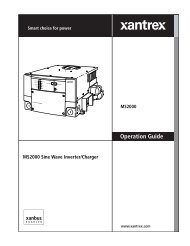
IntroductionAuto Restart AfterErrors.The <strong>PROsine</strong> protects itself against numerous conditions (e.g. AC overload orover temperature) by shutting down. You can program the <strong>PROsine</strong> to restartautomatically when the cause of the shutdown has corrected itself.Important: Auto Restart After Errors is factory-set to OFF since this feature cancause the <strong>PROsine</strong> to start unexpectedly and supply AC.Run Without PanelThe Run Without Panel configuration setting is an excellent recovery feature thatenables your <strong>PROsine</strong> to continue running if the display panel is disconnected orif its communication cable is damaged. Run Without Panel is factory-set to OFF.Materials ListYour <strong>PROsine</strong> <strong>2.0</strong> <strong>Inverter</strong>/<strong>Charger</strong> package includes the items listed below. SeeTable 1-1.• 1 <strong>PROsine</strong> <strong>2.0</strong> <strong>Inverter</strong>/<strong>Charger</strong>• 1 Display panel• 1 Communications cable (70ft; 21m)• 1 Battery temperature sensor with a 25ft (8m) cable• 2 DC terminal covers• 1 User’s Manual• 1 Quick Installation Guide (includes <strong>PROsine</strong> mounting template)• 1 Mounting template for display panel• 1 Quick Reference Guide• 1 ABYC Warning label1–6 445-0089-01-01
Materials ListImportant:p DC Wiring EnclosureFor residential installations, some installation codes may require a wiringenclosure for DC connections and cables. (Installation procedures are shippedwith the DC Wiring Enclosure.)p Crimp-On Ring Terminals (for DC Wiring Enclosure)If you are using the DC Wiring Enclosure, you should use crimp-on ringterminals on the <strong>PROsine</strong> end of your DC cables. Most box connectors (setscrew types) are too large to fit in the enclosure without the risk of theconnector shorting to the wall of the DC Wiring Enclosure. Do not use anyconnector that does not provide at least 2mm clearance to the inside wall withthe wire in place and the set screw tightened.p Series Sync CableIf you are connecting two <strong>PROsine</strong>’s in series, you will need a Series Synccable. This is a standard 4-connector telephone cable and may be purchasedfrom most electronics retailers.Contact <strong>Xantrex</strong> or your distributor about the Wiring Enclosure. Purchase thecrimp-on ring terminals from a local supplier.If any of these materials are missing or are unsatisfactory in any manner, pleasecontact Customer Service. See page WA–1.445-0089-01-01 1–7
Introduction<strong>PROsine</strong> <strong>2.0</strong> <strong>Inverter</strong>•<strong>Charger</strong>DC terminal coversBattery temperaturesensorDisplay panelUser’s ManualCommunications cableUser’s ManualQuick Installation GuideQuick Reference CardABYC Warning LabelFigure 1-1 <strong>PROsine</strong> Materials as ShippedImportant:: For Marine InstallationsFor marine installations, you must attach the ABYC Warning label in a conspicuouslocation on the AC load panel. The Warning label is supplied with your <strong>PROsine</strong> andis illustrated below.1–8 445-0089-01-01
Default Values for the <strong>PROsine</strong> SystemDefault Values for the <strong>PROsine</strong> SystemTable 1-1 lists the default settings for the <strong>PROsine</strong> system. Record your settings inthe right-hand column after you have configured the <strong>PROsine</strong>. This informationwill be valuable if you need to reconfigure your system or call <strong>Xantrex</strong> CustomerServiceTable 1-1 <strong>PROsine</strong> Default ValuesItem Default Value Your SettingsNOTEAt a minimum, configure the items marked with a ** after installation.Adjustable From the Configure <strong>PROsine</strong>—Basic MenuAC Breaker Size 15 amps **Adjustable From the Configure <strong>PROsine</strong>—Advanced MenuLoad SensingDisabledLoad Sense Power100 WattsLoad Sense Interval1 secondLow AC Transfer (V) 90VLow AC Transfer (Hz) 55HzHi AC Transfer (V)130VHi AC Transfer (Hz)65HzAC Series ModeStandalone<strong>Inverter</strong> Low V Shutdown 10V<strong>Inverter</strong> Low V Warning +0.5VIverter Low V Restart 2.5VHysteresisRun Without PanelNO<strong>Inverter</strong> Enabled on Reset DisabledWithout Panel<strong>Charger</strong> Enabled on Reset DisabledWithout PanelAuto Restart After Error NO **Adjustable From the Configure Display Panel MenuAudible AlarmOFFLCD Backlight Mode AutoLCD Backlight Brightness 50%LCD Backlight Timeout 20 secondsTemperatureFarenheit445-0089-01-01 1–9
IntroductionTable 1-1 <strong>PROsine</strong> Default ValuesItem Default Value Your SettingsAdjustable From the Configure Battery MenuNOTESettings below are for Battery Type = Generic Gel.Battery Size 200Ah **Default Battery Temperature WarmBattery Type Generic Gel **Battery Temp. Coefficient –27mV/°CBulk Mode Settings:• Max Voltage• Max Current (%C)• Threshold Voltage• Threshold TimeoutAbsorption Mode Settings:• Max Voltage• Max Current (%C)• Max Timeout• Threshold Current (%C)• Threshold TimeoutOvercharge Mode Settings:• Max Voltage• Max Current (%C)• Max TimeoutFloat Mode Settings:• Max Voltage• Max Current (%C)• Max Timeout• Threshold Voltage• Threshold TimeoutEqualize Mode Settings:• Max Voltage• Max Current (%C)• Max Timeout• Threshold Voltage• Threshold TimeoutConstant Mode Settings:• Voltage Setpoint• Current Setpoint<strong>Charger</strong> Mode<strong>Charger</strong> Type<strong>Charger</strong> High Battery VWarning Offset• 14.2V• 25%• 13.8V• 3min• 14.2V• 25%• 8hr• 1%• 3min• 14.2V• 20%• 0• 13.8V• 200%• 21days• 12.5V• 15min• 13.8V• 200%• 0• 0• 0• 13.5V• 100AStandalone3-Step1.0VNOTEThe values opposite the gray bar are set when you select a battery type. If you didnot subsequently change these settings, they do not need to be recorded.1–10 445-0089-01-01
2ProductOrientationChapter 2 will familiarize you with the following components of a<strong>PROsine</strong> system:• <strong>PROsine</strong> features. (Start on page 2–2.)• Display panel features. (Start on page 2–6.)• Battery temperature sensor. (See page 2–12.)
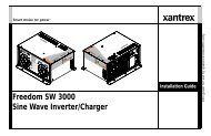
Product Orientation<strong>PROsine</strong> FeaturesAC EndDISPLAY BATTERY SYNCTEMPTemperatureFigure 2-1 AC End View (Blank Panel Option)FeatureDescription1 ON/OFF/REM Switch:ON: Normal operation according to the way the unit has been configuredvia the display panel.OFF: The inverter and charger are off; shorepower is not passed through tothe loads. The unit draws the lowest battery current possible (less than2mA).REM: With the switch in this position, the unit can be turned on and offremotely. (For details, see “ON/OFF/REMote Control of <strong>PROsine</strong>Operation” on page 5–3.)2 DISPLAY: Jack for the display panel.3 BATTERY TEMP/REMOTE: Jack for the battery temperature sensor.Also provides a connection for remote shutdown. See “Step 10: Connectingthe Remote Shutdown” on page 3–24.4 SYNC: Jack for synchronizing a second <strong>PROsine</strong> to produce 120/240Vsplit phase AC. For details, see Chapter 7, “Series Operation”.5 Removable panel. The blank panel option is shown. For details, see “ACPanel Options” on page 2–3. The AC wiring compartment is locatedbehind the panel.6 Knockouts for AC wiring7 Mounting flange2–2 445-0089-01-01
<strong>PROsine</strong> FeaturesAC Panel OptionsThe <strong>PROsine</strong> has two AC panel options, each of which includes one 30Ahardwire output circuit:• Blank access panel: one hardwire output circuit. See Figure 2-1.• Panel equipped with 15A GFCI receptacle and one hardwire output circuit.See Figure 2-2.Figure 2-2 Panel Equipped With GFCI and Circuit ProtectorFeatureDescription1 GFCI Duplex Receptacle2 15A circuit protector for GFCI445-0089-01-01 2–3
Product OrientationDC End BFigure 2-3 DC EndFeatureDescription1 Positive DC cabling terminal, 8 mm stud2 Negative DC cabling terminal, 8 mm stud3 Cooling fan. (For details, see “Fan Operation” on page 5–3.)4 Screw holes for mounting accessory modules5 Chassis ground lug. Provides a ground path for the <strong>PROsine</strong> chassis to theDC system ground.6 Screw holes for mounting the optional DC wiring enclosure. See“Materials List” on page 1–6 for information about the crimp-on ringterminals to be used with this option.2–4 445-0089-01-01
<strong>PROsine</strong> FeaturesDC Terminal CoversTwo covers—red for positive and black for negative—are supplied to preventaccidental contact with the cabling connectors after installation.Figure 2-4 DC Terminal Cover: Top View on Left; Bottom View on Right445-0089-01-01 2–5
Product OrientationDisplay Panel FeaturesThe display panel lets you monitor and control the <strong>PROsine</strong> system. Forconvenience, the liquid crystal display (LCD) is backlit and the panel can beconfigured so an audible tone alerts you to any warnings or system faults thatoccur. The panel’s features are described below.Figure 2-5 <strong>PROsine</strong> Display Panel FeatureDescription1 DISPLAY mode switch2 INVERTER switch and status LEDs3 CHARGER switch and status LEDs4 Menu navigation and data selection buttons5 LCD display6 Two input jacks (not illustrated) on the bottom of the unit behind thefaceplate. Either jack can be used for the communication cable thatconnects the panel to the <strong>PROsine</strong>. The second jack can be used to connectfuture accessories.2–6 445-0089-01-01
Display Panel FeaturesDISPLAY Mode SwitchSwitch PositionONOFFCONFIGUREDescriptionPuts the unit in Display mode. Data Display screens are shown soyou can monitor system performance.Power continues to be available to the panel so vital data likesystem errors and warning statuses can be checked.Puts the inverter in Configure mode. Configuration screens areavailable, and you can configure the system without turning on theinverter and charger functions.445-0089-01-01 2–7
Product OrientationINVERTER SwitchThis switch is active in all Display modes: ON, OFF, CONFIGURE.Switch PositionENABLEDISABLEDescriptionThe inverter is enabled and will run if there is no shorepower.(NOTE: Throughout this manual, the term “shorepower” refers toAC input power from a utility grid, generator, or other source.)When the AC power does not meet configuration parameters (i.e. is“bad”), the inverter is off and will consume minimal power.When the AC power is good, the inverter is off and will consumeminimal power. The <strong>PROsine</strong>’s transfer relay is in the “PassThrough” position. (The transfer relay allows shorepower to passthrough the <strong>PROsine</strong> to the AC output terminals whenever AC isconnected unless there is an error, or the <strong>PROsine</strong> is turned Offwith the <strong>PROsine</strong> ON/OFF/REM switch.)INVERTER LEDsThe LEDs are continuously updated whenever the Display Mode switch is set toON or CONFIGURE.LEDSTANDBYandINVERTINGAC INDescriptionSTANDBYLED StatusINVERTINGLED StatusOFF OFF <strong>Inverter</strong> is not running because it has not been enabled or asystem error has occurred.OFF ON The unit is inverting.ON OFF Invert is enabled, but the unit is not inverting because of anerror or because shorepower is “good.”INVERT FLASHING Unit is searching in Load Sense mode.OFFONFLASHING“Good” shorepower has not been detected.“Good” shorepower has been detected.Shorepower line and neutral are reversed or neutral isdisconnected. Have an electrician check the wiring.2–8 445-0089-01-01
Display Panel FeaturesCHARGER SwitchThis switch is active in all Display modes: ON, OFF, CONFIGURE.Switch PositionENABLEDISABLEDescriptionThe charger is enabled and will charge the battery according tothe way the unit is configured if shorepower is “good.”The charger is off and will consume minimal power.CHARGER LEDsThe LEDs are continuously updated whenever the Display Mode switch is set toON or CONFIGURE.LEDSTANDBYandDescriptionSTANDBYLED StatusCHARGINGLED StatusOFF OFF The charger is not running because it is not enabled, the chargecycle has been completed, or a system error has occurred.OFF ON The charger is running.CHARGING ON OFF The charger is enabled but is not running because shorepoweris not “good.”EQUALIZEREADYOFFONFLASHINGOFFONEqualize mode has not been selected.The charger is in Equalize mode and the batteries are charging.CAUTION: Battery voltage may go up to 17V.Equalize mode has been selected; the charger is presentlyexecuting the basic charge cycle in preparation forEqualization mode. (The CHARGING LED is also on in thisstage.)The charger is not running, or the Charge cycle is not finished.The Charge cycle is complete. The battery is fully charged.445-0089-01-01 2–9
Product OrientationLCD PanelThe LCD panel lets you monitor the <strong>PROsine</strong> system and change its configurationsettings. It operates in two basic modes: Data Display and Configuration.Data Display Mode• In Data Display mode the screens provide information about <strong>PROsine</strong> systemperformance.• You can cycle through them by pressing the Up s and Down t Menubuttons. (In Data Display mode, the other buttons have no function.)• Typically, the top line indicates the type of data being displayed and the actualdata appears on the bottom line. A sample screen is shown below:<strong>PROsine</strong>: Battery1<strong>2.0</strong>V +10A 22°C• Examples of all the Display screens are shown on page 5–10.Configuration Mode• In Configuration mode, the screens show data that can be changed as well asread-only data. (For details about each Configuration screen, see, Chapter 4,“Configuration”.) Using these screens, you can:• Define the operating parameters of the <strong>PROsine</strong> (including AC breakersize, battery size, battery type, types of charge, load sense capability, etc.)• Adjust the display characteristics of the panel (including an audible alert,screen contrast, and screen backlighting)• View current operational data, Warning messages, Error messages, andPanel fault messages in order to monitor and troubleshoot systemperformance• Two sample screens are shown below:Menu 1: Configure<strong>PROsine</strong>—GeneralAC Breaker Size*15A2–10 445-0089-01-01
Display Panel FeaturesMenu Navigation and Data Selection ButtonsWhen the DISPLAY switch is set to CONFIGURE, the menu navigation and dataselection buttons operate as follows:Press This ButtonToESCAPE • Cancel changes made to data• Back up one menu levelsMENU UpsMENU DownsDATA UpsDATA DownsENTERsBack up one menu itemProceed to next menu itemIncrease data value or cycle through available optionsDecrease data value or cycle through available optionsSave changes or proceed to next menu levelExamples of how to change configuration settings are given on page 4–3.Further information about viewing Display mode screens is provided on page 5–10445-0089-01-01 2–11
Product OrientationBattery Temperature SensorThe temperature sensor continuously measures the temperature of the battery andadjusts charger output for a more accurate, temperature-compensated charge.Figure 2-6 Battery Temperature SensorFeatureDescription1 Mounting plate. Connects to the negative battery terminal.2 Sensor. Reverse side has peel-off backing and self-adhesive strip so youcan attach the sensor to the side of the battery case.3 Sensor cable (25ft; 8m).4 Connector. Plugs into the Battery Temp jack on the <strong>PROsine</strong>.NOTE: The battery temperature sensor is electrically isolated from the mounting plate.2–12 445-0089-01-01
3 InstallationChapter 3 This section gives complete information for installing a<strong>PROsine</strong> system.Specifically, this section describes:• Safety instructions and installation codes that must be observedduring installation• Installation tools and materials• Appropriate locations and environments for mounting the<strong>PROsine</strong>, display panel, and battery temperature sensor• AC cabling, DC cabling, and grounding information• Detailed installation procedures on page 3–3.For information about installing two <strong>PROsine</strong>s in series, see Chapter7, “Series Operation”.
InstallationSafety InstructionsInstallation CodesWARNING: Shock hazard<strong>Xantrex</strong> Technology recommends that all wiring be done by a certified technician orelectrician to ensure adherence to approved electrical wiring regulations.• Before you begin the installation, review the “Important Safety Instructions”on “Important Safety Instructions” on page vii, and read the entire“Installation” section so you can plan your installation from beginning to end.• Disconnect all AC and DC power sources to prevent accidental shock.Disable and secure all AC and DC disconnect devices and automaticgenerator starting devices.Governing installation codes vary depending on the specific location andapplication of the installation. Some examples include the following:• The U.S. National Electrical Code (NEC)• The Canadian Electrical Code (CEC)• The American Boat and Yacht Council (ABYC) and the US Coast Guardrequirements for installations on marine vessels• The U.S. Code of Federal Regulations (CFRs)• Canadian Standards Association (CSA) and the RV Industry Association(RVIA) for installations in RVsIt is the installer’s responsibility to ensure that all applicable installationrequirements are met.3–2 445-0089-01-01
Safety InstructionsInstallation Tools and MaterialsYou will need the following to install the <strong>PROsine</strong>, display panel, and batterytemperature sensor:p Wire stripperp Mounting screws or boltsp #2 Phillips screwdriverp Wrench for DC terminals (1/2 inch or 13mm or adjustable)ppppppAC cable (i.e. 2-conductor-plus-ground cable), sized appropriately for loadand applicationWire nuts or crimp connectors for AC wire and appropriate toolsTwo 1/2 inch strain-relief clamps for AC cablesDC cable, sized appropriately for load and applicationLugs for DC cables to fit 8 mm (5/16 in.) DC stud terminals) as well asappropriate tools (e.g. crimping tool)AC and DC disconnects and over-current protective devicesImportant: For residential installations, installation codes may require a wiringenclosure for DC connections and cables. Contact <strong>Xantrex</strong> or your distributor for this part.Installation ProceduresThis section provides detailed installation information. For your convenience, theoverall procedure is divided into ten main steps:p Step 1: Designing an installation. (Start on page 3–4.)p Step 2: Choosing a location for the <strong>PROsine</strong>. (Start on page 3–9.)p Step 3: Mounting the <strong>PROsine</strong>. (Start on page 3–10.)p Step 4: Connecting the AC input wiring. (Start on page 3–11.)p Step 5: Configuring the output neutral bonding system. (Start on page 3–13.)p Step 6: Connecting the AC output wires. (Start on page 3–15.)p Step 7: Connecting the DC cables. (Start on page 3–17.)p Step 8: Mounting the display panel. (Start on page 3–20.)p Step 9: Connecting the battery temperature sensor. (Start on page 3–21.)p Step 10: Connecting the remote shutdown feature. (Start on page 3–24.)445-0089-01-01 3–3
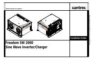
InstallationStep 1: Designing the InstallationAll types of <strong>PROsine</strong> installations share common components, and these arebriefly described below. Figure 3-1 shows these components and their relationshipto each other in a typical recreational vehicle or fleet vehicle installation. (Fordiagrams of typical residential backup and marine systems as well as seriesinstallations, see Appendix B, “System Diagrams”.)DC Fuse /Disconnect orCircuit BreakerAC Load PanelAC Source Panelto engine–+◦lAutomatic or Manual ACSource Selector SwitchVehicle StartingBatteryShorepowerFigure 3-1 Typical Recreational Vehicle and Fleet Vehicle Installation3–4 445-0089-01-01
Step 1: Designing the InstallationAC shorepowerA source of 120 volt, 60Hz alternating current is needed to provide energy forcharging batteries and to pass through to AC loads. This source could be the utilitygrid (power company) or an AC generator. An automatic or manual AC sourceselector switch can be used to connect one of the multiple sources of shorepowerto the <strong>PROsine</strong> system.Important: Throughout this manual, the term “shorepower” refers to AC input powerfrom a utility grid, generator, or other source.GeneratorAC Disconnect andOver-CurrentProtection DeviceThe <strong>PROsine</strong> is compatible with virtually all generators which produce nominally120Vac 60Hz power. The best generators produce a sinewave output, othersproduce a distorted sinewave, and the lower quality generators produce a"modified sinewave" (MSW) or squarewave output. The <strong>PROsine</strong> will operatecorrectly on sinewave or distorted-sinewave generators; it will also operatecorrectly on most MSW or squarewave generators but some models of thesegenerators may prove incompatible. See Chapter 6, “Troubleshooting” for errorsrelated to generator incompatibility.Since the charging current limit of the <strong>PROsine</strong> may be configured all the waydown to 0A it is possible to use very small generators with the <strong>PROsine</strong> to chargebatteries. <strong>Xantrex</strong> has operated the <strong>PROsine</strong> from a generator as small as 700W.To do this, configure the "AC Breaker Size" (found in Configure <strong>PROsine</strong> —Basic Menu on page 4–7) to a current rating compatible with the generator size.For example, 6A should work well with a 700W generator, 8A should work with a1000W generator - experiment to find the largest setting that the generator canaccommodate. To operate the <strong>PROsine</strong> at the full 100A charging current rating<strong>Xantrex</strong> recommends a 2kW generator or larger and a breaker size setting of 20A.To meet CSA, UL, and electrical code requirements, the <strong>PROsine</strong>’s AC and DCinputs and outputs must be provided with over-current protection (such as a circuitbreaker or fuse) and a disconnect device, as follows:AC Input: The circuit breaker or fuse used to protect the <strong>PROsine</strong> must berated no more than 30A and must be approved for use on 120Vac branchcircuits. The wire used between the breaker and the <strong>PROsine</strong> input must besized to match the circuit breaker, in accordance with the electrical codes orregulations applicable to your installation. The “AC Service Rating” setting ofthe <strong>PROsine</strong> must also be set to match the size of the breaker provided. (SeeChapter 4, “Configuration” and the following section.)AC Output: The circuit breaker or fuse must be rated at no more than 30Aand must be approved for use on 120Vac branch circuits. The wire usedbetween the <strong>PROsine</strong> and the AC output breaker must be sized to match theAC input circuit breaker’s rating. The wire from the AC output breaker toyour loads must be matched to the rating of the AC output breakers.Disconnect Devices: Each system requires a method of disconnecting theAC circuits. If the over-current protection device is a circuit breaker, it willalso serve as the disconnect. If fuses are used, separate AC disconnectswitches will be needed ahead of the fuses.445-0089-01-01 3–5
InstallationAC DistributionPanelsMost systems incorporate distribution centers both ahead of the <strong>PROsine</strong> (the ACsource panel) and between the <strong>PROsine</strong> and the loads (the AC load panel). Asource panel includes a main circuit breaker, which serves as over-currentprotection and as a disconnect for the AC shorepower supply line. Additionalcircuit breakers serve individual circuits, one of which serves the <strong>PROsine</strong>. TheAC load panel can incorporate both the main 30A AC output circuit breaker andbreakers for individual load circuits.Important: Do not connect the output of a single <strong>PROsine</strong> to what is known as a“multi-wire branch circuit”. These are 4-wire circuits consisting of a ground, neutral, andtwo lines that are 180 degrees out of phase with each other (from a standard 120/240V“split phase” circuit). These circuits are commonly used in kitchens to power “splitreceptacles” where the top and bottom halves of a duplex receptacle are connected todifferent lines. If you need to run multi-wire branch circuits from your inverter system,you will need to use two <strong>PROsine</strong> units in a series system to create 120/240Vac split-phasepower. For details, see Chapter 7, “Series Operation”. For more information about multiwirebranch circuits, refer to the US National Electrical Code (NFPA 70, 1999) para 210–4 and the Canadian Electrical Code (CSA C22.1-1998) section 26–710.AC CablingAC cabling includes all the wires and connectors between the AC source and the<strong>PROsine</strong> and all cabling between the <strong>PROsine</strong> and the AC panels, circuitbreakers, and loads. The type and size of the wiring varies with the installationand load. For marine and some RV applications, flexible multiple-strand wire isrequired. For residential installations, solid Romex cable is often used.Installation codes may specify solid or stranded, overall size of the conductors,and type and temperature rating of the insulation around the wire.AC wiring must be sized to match the current rating of the AC breakers youprovide on the input and output AC circuits in accordance with the electricalcodes or regulations applicable to your installation. Table 3-1 is based on the U.S.National Electrical Code and the Canadian Electrical Code, assuming 2-conductor-plus-ground cable. Other codes and regulations may be applicable toyour installation.Table 3-1 Required AC Wire Size vs Breaker RatingBreaker Size 10A 15A 20A 30AMinimum Wire Size 14AWG 14AWG 12AWG 10AWGAC Output NeutralBondingThe neutral conductor of the <strong>PROsine</strong>’s AC output circuit is automaticallyconnected to the safety ground during inverter operation. When AC utility poweris present and the <strong>PROsine</strong> is in <strong>Charger</strong> mode, this connection is not present, sothat the utility neutral is only connected to ground at your source panel. Thisconforms to National Electrical Code requirements that separately derived ACsources (such as inverters and generators) have their neutral conductors tied toground in the same way that the neutral conductor from the utility is tied to groundat the AC source panel.3–6 445-0089-01-01
Step 1: Designing the InstallationDC CablingThis includes all the cables and connectors between the batteries, the DCdisconnect and over-current protection device, and the <strong>PROsine</strong>. All installationsrequire multi-strand insulated cables as well as disconnect and over-currentdevices. DC cable sizes are indicated by AWG notation or MCM notation. Underthe AWG standard, a larger gauge number indicates a smaller wire diameter.Under the MCM standard, a larger number indicates a larger cable. Wire size isusually marked on the cables for sizes this large. Table 3-2 specifies the minimumDC cable size and maximum fuse size for the <strong>PROsine</strong>. The DC cables must becopper and must be rated 75°C minimum. The cables should be terminatedwith lugs that fit the DC stud terminals snugly (8 mm or 5/16 in. hole size).Table 3-2 Required DC Cable and Fuse SizeDC Cable Length Cable Size Fuse AmpsLess than 6 feet 250MCM 300A class TBetween 6 and 12 feet 350MCM 300A class TImportant: Using the correct cable size is critical to achieving the rated performance ofthe <strong>PROsine</strong> unit. When starting a heavy load the <strong>PROsine</strong> can draw current surges fromthe battery of up to 600A. If the wire is too small the voltage drop from this surge willresult in a voltage at the <strong>PROsine</strong> terminals that is too low for the <strong>PROsine</strong> to operatecorrectly. The <strong>PROsine</strong> may appear to operate correctly with smaller cables until a heavyload such as an air conditioner attempts to start - then the unit may work correctlysometimes and not work correctly other times.DC Disconnects andOver-CurrentDevicesBatteriesGround FaultCircuit Interrupters(GFCIs)The DC circuit from the battery to the <strong>PROsine</strong> must be equipped with adisconnect and over-current device. This usually consists of a circuit breaker, a“fused-disconnect,” or a separate fuse and DC disconnect. Do not confuse ACcircuit breakers with DC circuit breakers. They are not interchangeable. Therating of the fuse or breaker must be matched to the size of cables used inaccordance with the applicable installation codes. The breaker or disconnect andfuse should be located as close as possible to the battery, in the positive cable.Applicable codes may limit how far the protection can be from the battery.Every <strong>PROsine</strong> system requires a deep-cycle battery or group of batteries thatprovide the DC current that the <strong>PROsine</strong> converts to AC. Different battery typesand sizes are available; many of these are discussed in Application Note: BatteryBanks for <strong>Inverter</strong> Systems (976-0114-01-01). Automotive-type starting or“cranking” batteries are not recommended, except for temporary emergency use.The <strong>PROsine</strong> uses 12-volt battery banks.A GFCI is a device that de-energizes a circuit when a current to ground exceeds aspecified value that is less than that required to blow the circuit breaker. GFCIsare intended to protect people from electric shocks and are usually required in wetor damp locations.445-0089-01-01 3–7
InstallationInstallations in marine and recreational vehicles may require GFCI protection ofbranch circuits connected to the AC output of the <strong>PROsine</strong>. In addition, electricalcodes require GFCI protection of certain receptacles in residential installations.While the true sine wave output of the <strong>PROsine</strong> is equivalent to the waveformprovided by utilities, compliance with UL standards requires that <strong>Xantrex</strong> test andrecommend specific GFCIs. As of October 2005, <strong>Xantrex</strong> has tested the GFCIprotected15A receptacles listed in Table 3-3 and found that they functionproperly when connected to the AC output of the <strong>PROsine</strong>.Table 3-3 Tested GFCI ModelsManufacturerLevitonCooper/EaglePass & SeymoreModel Number a8598, 8599, 8898, 8899, 6598 b , 6599 bXGF15, XGF20, GF15 b , GF20 b1594, 2094, 1591 bHubbell/Bryant GF52*A c , GF53*A c , GF82*A c , GF83*A c , GFR5252*A c , GFR5352*A c , GF8200*A c ,GF8300*A c , GF52 b , GF53 b , GF82 b , GF83 b , GF5252 b , GF5352 b , GF8200 b , GF8300 ba.GFCI models may change over time. Refer to the Application Note “Using GFCI Receptacles on <strong>Xantrex</strong><strong>Inverter</strong>s and <strong>Inverter</strong> <strong>Charger</strong>s” on the <strong>Xantrex</strong> website for up-to-date test results.b.This is an old model and is generally no longer sold as it does not offer the same level of protection as thenewer models.c.The asterisk * represents one or two letters to indicate the front color of the receptacle. The A indicates thatthis is the newer model which meets the latest safety standard.3–8 445-0089-01-01
Step 2: Choosing a Location for the <strong>PROsine</strong>Step 2: Choosing a Location for the <strong>PROsine</strong>WARNING: Fire and explosion hazardThis equipment contains components that tend to produce arcs or sparks. To prevent fire orexplosion, do not install the <strong>PROsine</strong> in compartments containing batteries or flammablematerials or in locations that require ignition-protected equipment. This includes anyspace containing gasoline-powered machinery, fuel tanks, or joints, fittings, or otherconnections between components of the fuel system.WARNING: Fire hazardTo reduce the risk of fire, do not cover or obstruct the ventilation openings. Do not installthe <strong>PROsine</strong> in a zero-clearance compartment. Overheating may result.The <strong>PROsine</strong> should only be installed in locations that meet the followingrequirements:ppppppDry. Do not allow water or other fluids to drip or splash on the <strong>PROsine</strong>. Donot mount the <strong>PROsine</strong> in an area subject to splashing water or bilgewater.Cool. Normal air temperature should be between 32°F and 104°F (0°C and40°C)—the cooler the better.Ventilated. Allow at least 5 in. (13cm) of clearance at the DC end of the<strong>PROsine</strong> for air flow, 1 in. (2.5cm) on each side, and 2 in. (5cm) at the ACend. For cooling, the volume of the enclosure is not as important as the overallsupply of air. The more clearance for ventilation around the unit, the better theperformance. Do not allow the ventilation openings on the ends of the unit tobecome obstructed.Safe. Do not install the <strong>PROsine</strong> in the same compartment as batteries or inany compartment capable of storing flammable liquids like gasoline.Close to the battery compartment and the AC source and load panels.Avoid excessive cable lengths (which reduce input and output power due towire resistance). Use the recommended cable lengths and sizes.Protected from battery acid and gases. Never allow battery acid to drip onthe <strong>PROsine</strong> or its wiring when reading specific gravity or filling the battery.Also do not mount the unit where it will be exposed to gases produced by thebatteries. These gases are very corrosive, and prolonged exposure willdamage the <strong>PROsine</strong>.445-0089-01-01 3–9
InstallationStep 3: Mounting the <strong>PROsine</strong>To mount the <strong>PROsine</strong>:1. Remove the <strong>PROsine</strong> from its shipping container, verify that all componentsare present, and record relevant product information on “Information AboutYour System” on page WA–4.2. Turn off the ON/OFF/REM switch on the AC end.3. Select an appropriate mounting location and orientation. (See Figure 3-2.) Tomeet regulatory requirements, the <strong>PROsine</strong> must be mounted in one of thefollowing orientations:• In a horizontal position on a vertical surface with the AC knockouts nearthe top as shown in Figure 3-2• On a horizontal surface• Under a horizontal surfaceSide near ACknockoutsmust be up.Figure 3-2 Approved Mounting Orientations4. The <strong>PROsine</strong> Quick Installation Guide has a mounting template printed on it.Tape it to the mounting surface and pilot-drill the desired number of mountingholes. Remove the template.5. Fasten the <strong>PROsine</strong> to the mounting surface. If you are mounting the unit on awall or bulkhead, use #12 or #14 pan-head wood or sheet metal screws tosecure it to the framing behind the wall or bulkhead. Alternatively, use nutinserts and 1/4-20 machine screws.3–10 445-0089-01-01
Step 4: Connecting the AC Input WiresStep 4: Connecting the AC Input WiresWARNING: Fire, Shock and Energy hazardsMake sure wiring is disconnected from all electrical sources before handling. All wiringmust be done in accordance with local and national electrical wiring codes. Do not connectthe output terminals of the <strong>PROsine</strong> to any incoming AC source.General AC Wiring ConsiderationsAC WiringConnectorsAC and DC WiringSeparationAC WiringCompartmentConnect AC wires with twist-on wire nuts or crimp-on splice connectorsaccording to the type of installation:• On a boat, use crimp-on splice connectors to meet the American Boat andYacht Council’s Standards and Recommended Practices for Small Craft,which do not allow twist-on connectors for AC connections.• For non-marine installations subject to vibration, you should still use crimponconnectors.• For non-marine installations in locations not subject to vibration, twist-onwire nuts may be used instead of crimp-on connectors.• The amount of insulation you strip off individual wires will be specified bythe connector manufacturer and is different for different types of connectors.Do not mix AC and DC wiring in the same conduit or panel. Where DC and ACwires must cross, make sure they do so at 90° to one another. Consult code fordetails about DC and AC wiring in vicinity to each other.For your reference, the AC Wiring Compartment is shown in Figure 3-3.Figure 3-3 Interior of AC Wiring Compartment445-0089-01-01 3–11
InstallationAC Input ConnectionsFigure 3-4 is a cutaway top view of the <strong>PROsine</strong> wiring compartment. It showsone incoming AC cable and its connections to the <strong>PROsine</strong> wires.To make the AC input connections:1. Run 10AWG 2-conductor-plus-ground cable through one of the cable clampson the AC end.2. Strip about two inches of the jacket from the AC cable and separate the threewires.3. Connect the incoming black and white (line and neutral) wires to the <strong>PROsine</strong>AC input black and white wires.4. Connect the incoming ground wire to the screw on the chassis marked .Use a crimp-on ring terminal if the AC input ground wire is stranded. Solidwire can be screwed directly under the head of the screw.grounding screwCutaway view of<strong>PROsine</strong> wiringcompartment asseen from the top.AC cableclampfor AC cablewire nuts or crimpconnections (dependingon type of installation)Figure 3-4 Incoming AC Cable (Top, cutaway view of wiring compartment)3–12 445-0089-01-01
Step 5: Configuring the Output Neutral Bonding SystemStep 5: Configuring the Output Neutral Bonding SystemAC Output Neutral-to-Ground Bonding SystemThe <strong>PROsine</strong> provides an installer-defeatable system that automatically connectsthe neutral conductor of the inverter AC output circuit to safety ground(“bonding” it) during inverter operation, and disconnects it (“un-bonding” it)when the <strong>PROsine</strong> has connected to AC shorepower. This system is designed toconform to installation codes that require single-phase AC sources such asinverters and generators to have their neutral conductors tied to ground in thesame way that the neutral conductor from the utility is tied to ground.These same codes specify that the neutral can only be connected to ground in oneplace at any one time. Any AC source feeding the <strong>PROsine</strong> is required to have itsneutral already connected to ground. Therefore, to keep from connecting theneutral to ground in a second place, the <strong>PROsine</strong> transfer relay breaks its ownneutral ground connection when connected to shorepower.This automatic neutral-to-ground bonding system is suited for installations inwhich the AC shorepower source is known to have a bonded neutral. This will bethe case in most situations: in a utility feed after the AC source panel, at an RVpark hook-up, at a marina’s shorepower hook-up, or with a generator with abonded neutral.In some installations, however, the AC shorepower source will not have a bondedneutral. This is true on some generators and it is true in certain utility-feedsituations. To accommodate these situations, the <strong>PROsine</strong> automatic neutralbonding system can be defeated, so the <strong>PROsine</strong> will not bond the neutral in anymode of operation. This allows the installer to bond the neutral in the AC loadpanel to provide the required single-point bonding of the neutral.To enable and disable the automatic AC output neutral-to-ground bondingsystemWARNING: Fire and Shock hazardAC neutral bonding system settings should only be changed by a qualified installer awareof the implications of the changes. Disconnect all AC and DC sources before working inthe AC wiring compartment or before making a setting change.You enable and disable the system using a screw in the AC wiring compartment,identified as the “Invert Mode Output Neutral-to-Ground Bonding Screw”. (SeeFigure 3-3.) This screw is identified with a label that indicates two different holesthat the screw can be mounted in. One hole is identified as the one that enables theautomatic bonding system, and the other hole defeats it so that the neutral is notbonded by the <strong>PROsine</strong> in any mode.445-0089-01-01 3–13
InstallationThe <strong>PROsine</strong> is shipped with the screw in the position that enables the automaticbonding system.• To disable the system, move the screw to the other hole.• Do not remove the screw from the product: make sure it is always installed inone position or the other, as appropriate for the configuration of the rest of thesystem.Table 3-4 AC Output Neutral-to-Ground Bonding Screw SettingsBonding ScrewSettingStatus of BondingInternal to the <strong>PROsine</strong>Neutral Bonding RequiredExternal to the <strong>PROsine</strong>AC shorepower notpresent (unit Invertingor in Standby)AC shorepower present(unit Charging or inStandby)In the AC inputshorepowersourceIn the AC loadpanelAutomaticbondingOutput neutral bondedOutput neutralun-bondedYesNoUn-bonded inall modesOutput neutral unbondedOutput neutral unbondedNoYes3–14 445-0089-01-01
Step 6: Connecting the AC Output WiresConnections for Hardwire OptionTwo options are available for AC output wiring:• Hardwire output.• Single hardwire output plus GFCI receptacle.Step 6: Connecting the AC Output WiresTo make the AC output wiring connections1. Run 10AWG 2-conductor-plus-ground cable through one of the cable clampson the AC end.2. Strip about two inches of the jacket from the AC cable and separate the threewires. Strip insulation from each of the wires according to the guidelinesgiven by the connector manufacturer.3. Connect the outgoing black and white (line and neutral) AC wires to the<strong>PROsine</strong> AC output black and white wires.4. Connect the incoming ground wire to the chassis using one of the screwsmarked .5. Connect the outgoing AC wires to an AC load panel equipped with circuitbreakers.grounding screwCutaway view of<strong>PROsine</strong> wiringcompartment asseen from the top.AC cableclampfor AC cablewire nuts or crimpconnections (dependingon type of installation)Figure 3-5 Hardwire AC Output Option (Top, cutaway view of wiringcompartment)445-0089-01-01 3–15
InstallationConnections for Single Hardwire Output With GFCIFigure 3-6 is a cutaway top view of the <strong>PROsine</strong> wiring compartment showingone set of outgoing AC wires with the GFCI option.To make the AC output wiring connections1. Run 10AWG 2-conductor-plus-ground through one of the cable clamps on theAC end.2. Strip about two inches of the jacket from the AC cable and separate the wires.Strip insulation from each of the wires according to the guidelines given bythe connector manufacturer.3. Connect the outgoing black and white (line and neutral) AC wires to the<strong>PROsine</strong> black and white AC output wires.4. Connect the outgoing ground wire to the chassis using one of the screwsmarked .5. Tuck the wires into the left-hand side of the wiring compartment so they don’tinterfere with the GFCI assembly.WARNING: Shock hazardIf you are not using the hardwire output circuit, you must cap off its line and neutral wires.Use twist-on wire nuts where allowed; use crimp-on wire caps in other applications.grounding screwCutaway view of<strong>PROsine</strong> <strong>2.0</strong> wiringcompartment asseen from the top.Do notdisturbfactorywiring.outgoingAC cablewire nuts or crimp-onwire caps (dependingon type of installation)GFCIFigure 3-6 Single Hardwire Output With GFCI3–16 445-0089-01-01
Step 7: Connecting the DC CablesStep 7: Connecting the DC CablesCAUTIONBefore making the final DC connection, check cable polarity at both the battery and the<strong>PROsine</strong>. Positive must be connected to positive; negative must be connected to negative.Reversing the positive and negative battery cables will damage the <strong>PROsine</strong> and void yourwarranty. This type of damage is easily detected.WARNING: Fire hazardUse only copper wire rated 75°C minimum. Make sure all DC connections are tight to atorque of 216–240 inch-pounds (24–27Nm). Loose connections will overheat.Follow the procedure given below to connect the battery leads to the terminals onthe DC end. The cables should be as short as possible and large enough to handlethe required current, in accordance with the electrical codes or regulationsapplicable to your installation. Table 3-2 on page 7 specifies the minimumDC cable size and maximum fuse size for the <strong>PROsine</strong>.Do not route your DC cables through an electrical distribution panel, batteryisolator, or other device that will cause additional voltage drops.Figure 3-7 shows the DC end for your reference.BFigure 3-7 DC End445-0089-01-01 3–17
InstallationTo make the DC connectionsRefer to Figure 3-8.1. Cut the cables to the correct length with enough insulation stripped off so youcan properly install the type of terminals you will be using.The terminals on the DC end are designed to fit up to 500MCM crimp-on ringterminals (either AMP or ILSCO) or box connectors.2. Attach the connectors to both cables.If you are using crimp connectors, use the tool recommended by the terminalmanufacturer. Make sure no stray wire strands protrude from the terminals.Important: For residential installations, the installation code may require a DC wiringenclosure for DC connections and cables. If you are using this accessory, secure it to the<strong>PROsine</strong> before routing cables. Be sure to use crimp-on ring terminals on the <strong>PROsine</strong> endof the DC cables (as specified on “Materials List” on page 1–6), and follow the installationprocedure provided with the wiring enclosure. Contact <strong>Xantrex</strong> or your distributor for thispart.3. Route the DC supply cables from the battery bank to the <strong>PROsine</strong>.4. Install a fuse and disconnect or breaker between the <strong>PROsine</strong> and the battery.They must be installed in the positive side of the DC circuit, as close aspossible to the battery. This protects your battery and wiring in case ofaccidental shorting. (See Table 3-2 on page 3–7 for required fuse size.)5. Attach one connector on the positive cable to the positive DC terminal on theDC end, and then attach the other connector to the POSITIVE (+) terminal onthe fuse or breaker.Observe the polarities carefully while completing the installation. Use awrench to tighten to a torque of 216–240 inch-pounds (24–27Nm). Test thatthe cable is secure.6. Connect one connector on the negative cable to the negative terminal on theDC end. Before proceeding, check that cable polarity is correct, and thenconnect the other end of the cable to the NEGATIVE (–) terminal on thebattery.This is the last cable connection you make. A spark is normal when it is made.Use a wrench to tighten to a torque of 216–240 inch-pounds (24–27Nm). Testthat the cable is secure.7. Attach the DC terminal covers. (See Figure 3-8.)3–18 445-0089-01-01
Step 7: Connecting the DC CablesFigure 3-8 DC Cable ConnectionsDC GroundingTo connect the DC ground:The Chassis Ground lug on the DC end of the <strong>PROsine</strong> is used to connect thechassis of the <strong>PROsine</strong> to your system’s DC grounding point as required byregulations for some installations. Use copper wire that is either bare or providedwith green insulation. Do not use the DC Ground Lug for your AC grounding.(See the AC wiring instructions in this section.)Follow the guidelines below that correspond to your type of installation. Theseguidelines assume you are using the code-compliant DC supply cable and fusesizes indicated in this manual. If you are using different sizes, refer to theapplicable code for DC grounding details.• Recreational Vehicle Use 8AWG copper wire and connect it between theChassis Ground lug and the vehicle’s DC grounding point (usually the vehiclechassis or a dedicated DC ground bus).• Marine Use 2AWG copper wire that is bare or has insulation rated min.105°C, and connect it between the Chassis Ground lug and the boat’s DCgrounding bus or engine negative bus.• Residential Use 4AWG wire and connect it between the Chassis Ground lugand your system’s DC grounding point. This will usually be the AC serviceentrance grounding point or a separate ground rod. For a solar PV installation,this will usually be the same ground rod used to ground the PV array.445-0089-01-01 3–19
InstallationStep 8: Mounting the Display PanelThe communications cable supplied with the display panel is 70 feet long (21meters). If you want to replace the cable with one that is longer or shorter, use ahigh quality, 6-wire telephone extension cable. You can install the panel up to 100feet (30 meters) away from the <strong>PROsine</strong>.Flush mounting the panel on a wall, bulkhead, or panel requires an opening that isapproximately 4 inches x 4 inches (10cm x 10cm). About 1 1/4 inches (3cm) offree space is required within the wall to accommodate the depth of the panel. Besure there is no wiring or other obstructions within the wall before you make anopening.To mount the display panel:1. Choose a location that is dry, out of direct sunlight, free from corrosive orexplosive fumes, and otherwise appropriate for mounting an electronicdevice.2. Tape the mounting template (in the <strong>PROsine</strong> package) to the mounting surfaceand mark the locations of the mounting holes and the area to be cut away.3. Pilot-drill the mounting holes and cut out the hole in which the panel will beinserted.4. Route the communications cable(s) inside the wall and through the opening.5. Insert one of the cable’s connectors in either jack on the bottom of the panel.6. Place the panel in the opening and secure it with appropriate fasteners.7. Route the communications cable to the <strong>PROsine</strong> and insert the connector inthe jack labelled DISPLAY.3–20 445-0089-01-01
Step 9: Connecting the Battery Temperature SensorStep 9: Connecting the Battery Temperature SensorMounting OptionsYou can mount the battery temperature sensor (BTS) in one of two ways:• Mounting the sensor to the negative battery post allows the internal batterytemperature to be sensed and provides the most accurate results.• Attaching the sensor to the side of the battery using the self-adhesive backingalso provides good results in most situations.WARNING: Energy and Explosion hazardReview the “Important Safety Instructions” on page vii.Mounting to the Negative Battery TerminalTo mount the sensor on the negative battery terminal:See Figure 3-9.Figure 3-9 BTS Attached to Negative Battery Terminal445-0089-01-01 3–21
Installation1. Decide which battery is to be monitored.When all battery banks are located in the same compartment, select thebattery that requires the most frequent charging (in a boat or an RV, this isusually the “house” battery). Where a battery is located in a separatecompartment from other batteries, and where temperatures are constantly high(as in an engine room), it is a good idea to monitor this battery to keep it frombeing overcharged as a result of its constant high temperature. In thissituation, the cooler battery bank will be slightly undercharged since it will beat a lower temperature than the battery being monitored, but this procedurewill prolong the warmer battery’s life.2. Switch off all devices operating from the battery, or open the battery switch, ifpresent, to disconnect the battery.3. If the charger has been operating, wait ten minutes for any explosive batterygasses to dissipate.4. Remove the nut that secures the existing negative DC wire to the battery.5. Move or reorient the existing negative DC wire so there is a flat surface onwhich to seat the battery temperature sensor mounting plate. You may need tobend the ring terminal and/or wires downward to allow the sensor to seat onthe top surface of the upper ring terminal.6. Mount the sensor directly on top of the negative DC wire terminal, as shownin Figure 3-9, and tighten the terminal nut firmly.7. Check that the sensor and all wires are fastened securely.8. Turn the battery switch on again (if you opened it in step 2).9. Route the sensor cable to the <strong>PROsine</strong> and plug it into the BATTERY TEMPjack. Secure the cable along its length.Important: In this procedure, you must install the DC wire on the battery terminal first.Then the sensor is installed on top of the DC wire. This sequence is required to provide thebest connection to the battery and to thereby ensure correct performance of the sensor.3–22 445-0089-01-01
Step 9: Connecting the Battery Temperature SensorMounting to the Side of the Battery CaseTo mount the sensor on the battery caseSee Figure 3-10.Adhesive backing allowsfor easy mounting on sideof battery.Figure 3-10 BTS Attached to Battery Case1. Select the battery to be monitored (see step 1 in the preceding procedure).2. Select a side suitable for attaching the sensor.The surface where the sensor is to be mounted must be flat and free fromreinforcing ribs or other raised features. As well, this surface must be in directinternal contact with battery electrolyte, so do not install the sensor on a sidenear the top of the battery or on the battery’s top surface.3. Clean the selected area thoroughly to remove any oil or grease that couldprevent the sensor from adhering to the battery case, and allow the batterycase to dry thoroughly.4. Peel the protective backing from the self-adhesive strip on the rear of thesensor.5. Press the sensor firmly against the clean side of the battery to fix it in place.6. Route the sensor cable to the <strong>PROsine</strong> and plug it into the BATTERY TEMPjack. Secure the cable along its length.445-0089-01-01 3–23
InstallationStep 10: Connecting the Remote ShutdownWARNING: Shock hazardThis step should only be completed by qualified installers or technicians who have aknowledge of DC circuits.Connect only to an isolated Class 2 extra-low voltage power source as described below.Some installations may require remote shutdown capability. This feature enablesyou disable all circuitry in the <strong>PROsine</strong> and remove all power from the displaypanel using a remote shutdown switch (e.g. the ignition switch in a vehicle). Thisalso removes all power (inverter and shorepower) from the AC loads.The remote shutdown signal (RS+/RS–) requires a source of 5–18Vdc, which iscapable of supplying 5–18mA, to enable the <strong>PROsine</strong>. This power source must belimited to Class 2 levels by an approved 1A fuse. The power source will often beone of the existing system batteries: the vehicle starting battery or the <strong>PROsine</strong>battery. In this case, the 1A fuse must be located in the positive (+) side of thecircuit, as close as possible to the power source.Note that the remote shutdown feature will only function when the ON/OFF/REMswitch is set to REM.Materials RequiredYou need two high quality 26AWG, 4-conductor telephone cables with connectorsattached (one 10 feet maximum; one 100 feet maximum), one 1:2 phone linesplitter, and a 1A fuse and in-line fuseholder. In addition, you might require asingle pole, single throw switch (or alternatively, you can use a vehicle ignitionswitchedcircuit). You can obtain these from local hardware, electronics, andautomotive stores.Installation StepsSee Figure 3-11 and Figure 3-12.To connect the remote shutdown feature1. Select one of the two cables and cut it at a convenient location for connectingto your Remote Shutdown Switch.2. See Figure 3-11 to identify the RS+ and RS– wires.3. Insulate the two middle wires so they don’t short.4. Connect RS+ to the positive of a switched, fused voltage source of 5–18V.5. Connect the RS– to the return of this voltage source.6. Plug the cables into the splitter and connect to the <strong>PROsine</strong> as shown inFigure 3-11.The Remote Shutdown feature is now ready for use. For operating information,see “ON/OFF/REMote Control of <strong>PROsine</strong> Operation” on page 5–3.3–24 445-0089-01-01
Step 10: Connecting the Remote ShutdownPlug into Battery Tempjack on <strong>PROsine</strong>1:2 phoneline splitterBattery TemperatureSensor cable10 feet max.100 feet max.26AWG, 4-conductor telephone cableRS+Do notuse.RS–NOTE: The retaining clip ison the opposite side of theconnector.Top view of cable and connectorRS+Do notuse.RS–Figure 3-11 Cabling Details for Remote Shutdown Feature****Do not connect tothese wires; they areused for the BatteryTemperature Sensor.Next StepsFigure 3-12 Schematic for Remote Shutdown FeatureAt this point, you have installed the <strong>PROsine</strong> system and are now ready toconfigure it.1. Read the configuration procedures in Chapter 4, “Configuration”.2. Reconnect the AC shorepower supply.3. Use the display panel to configure the <strong>PROsine</strong>.445-0089-01-01 3–25
Installation3–26 445-0089-01-01
4 ConfigurationChapter 4 explains how to configure the <strong>PROsine</strong> to best meet yourelectrical system requirements. It is divided into three parts:• General Configuration Information on page 4–2.Tells you how to enter Configure mode and Installer mode, howto scroll through the configuration screens, and how to changeconfiguration settings.• Configuration Screens on page 4–4.Shows how the configuration menus and screens are organized.• Configuration Options on page 4–6.Lists all the configuration options as well as the availableconfiguration values or settings. Refer to Part 3 when you want toset specific configuration values.Important: he <strong>PROsine</strong> Quick Reference Guide supplied with your <strong>PROsine</strong>provides an overview of the configuration menus and options as well as a list ofselected default settings.
ConfigurationPart 1: General Configuration InformationEntering Configure ModeEntering Installer-Only ModeAll changes to the operation of the <strong>PROsine</strong> are made via the display panel. Theunit must be in Configure mode or Installer-Only mode before you can changesystem settings. It is essential that you understand the implications of changingUser and Installer settings. Be sure to study Chapter 3, “Installation” before youconfigure your system. Procedures for changing modes and values are givenbelow.To enter Configure mode:• Set the DISPLAY switch to CONFIGURE.This gives you access to all user-configurable items.WARNING: Fire hazardThe following information is for qualified installation/service personnel only. Incorrectconfiguration can lead to battery damage and risk of fire.If a parameter is “Installer-Only,” it is meant to be configured by a professional installerwho is not only familiar with the system settings on the inverter but also the ramificationsof changing those settings. Setting these parameters incorrectly could damage connectedequipment (e.g. batteries) or could severely affect the performance of your system. Youwill not be able to change parameters that are Installer-Only unless you place the displaypanel in Installer-Only mode.If you try to change settings on a screen that contains installer-only data and thepanel is not in Installer mode, this message appears for one second:To Change; Enter Installer ModeTo enter Installer-Only mode:• While the unit is in Configure mode, hold down the ESCAPE and DATA Downt buttons for 3–4 seconds.A message cautions you that the panel is now in Installer mode and explainshow to exit Installer mode.The next time you press a key, a message appears to remind you that the panelis still in Installer mode.Exit Installer-Only mode before you put the <strong>PROsine</strong> into service.4–2 445-0089-01-01
Part 1: General Configuration InformationChanging SettingsImportant: All configuration settings are stored in the <strong>PROsine</strong>’s memory andwill not be lost even if all power is disconnected.To change system settings:1. Set the DISPLAY switch to CONFIGURE.2. Press Up s MENU or Down t MENU to display the menu you want.3. Press ENTER once, and then press Up s MENU or Down t MENU until themenu item you want appears.4. Press Up s DATA or Down t DATA until the value you want appears.5. Press Up s MENU or Down t MENU until the setting you want appears.6. When the correct value is displayed, you can do one of three things:• Press ENTER to save the new setting.• Press ESCAPE to restore the old setting.• Press Up s MENU or Down t MENU to restore the old setting andmove to another item on the same menu.Important: Wherever you are in the menu structure, you can return to the highest levelby repeatedly pressing ESCAPE.Changing Settings:Example 1Changing Settings:Example 2The Audible Alarm is set to Disabled by default.To change the Audible Alarm to All Faults:1. Set the DISPLAY switch to CONFIGURE.2. Press Down t MENU until Configure Display Panel appears.3. Press ENTER once. The Audible Alarm menu item appears with an asterisk(*) beside Disabled.4. Press down t DATA until All Faults appears.5. Press ENTER to save this setting. (An * appears to the left of All Faults.)To adjust the Breaker Size setting:1. Set the DISPLAY switch to CONFIGURE.2. Press Down t MENU until Configure <strong>PROsine</strong>—Basic Menu appears.3. Press the ENTER button once. AC Breaker Size appears.4. Press Down t DATA or Up s DATA until the value you want appears.5. Press ENTER to save this setting.445-0089-01-01 4–3
ConfigurationResetting to Factory DefaultsTo reset the <strong>PROsine</strong> to the factory defaults:1. Disable Invert and Charge mode.2. Set the DISPLAY switch to CONFIGURE.3. Press Down t MENU until Configure <strong>PROsine</strong>—Advanced Menu appears.4. Press the ENTER button once.5. Press Down t MENU until Reset to Dflts appears.6. Press the ENTER button once.7. Hold down the ESCAPE and DATA Down t buttons for 3–4 seconds to enterInstaller mode.8. Press Down t DATA or Up s DATA until Load Factory appears.9. Press the ENTER button once.Part 2: Configuration Menus and ScreensTable 4-1 shows the organization of the configuration menus and screens. Thescreens are grouped into five menus:• Configure <strong>PROsine</strong>—Basic• Configure <strong>PROsine</strong>–Advanced• Configure Display Panel• Configure Battery• Diagnostics4–4 445-0089-01-01
Part 2: Configuration Menus and ScreensTable 4-1 Menu Structure—OverviewConfigure <strong>PROsine</strong>—Basic Configure <strong>PROsine</strong>—Advanced Configure Display Panel Configure Battery DiagnosticsAC Breaker SizeLoad SensingEqualizeLoad SensingLoad Sense PowerLoad Sense IntervalLow AC Transfer (V)Low AC Transfer (Hz)High AC Transfer (V)High AC Transfer (Hz)AC Series Mode<strong>Inverter</strong> Low V Shutdown<strong>Inverter</strong> Low V Warning<strong>Inverter</strong> Low V Restart HysteresisRun Without Panel<strong>Inverter</strong> After Reset Without Panel<strong>Charger</strong> After Reset Without PanelAuto Restart After ErrorReset to DefaultsAudible AlarmLCD Backlight ModeLCD Backlight BrightnessLCD Backlight TimeoutTemperature (C/F)Battery SizeDefault Battery TempBattery TypeView/Change Battery Details:• Battery Temp. Coefficient• Bulk Charge Mode Settings• Max Voltage• Max Current (%C)• Threshold Voltage• Threshold Timeout• Absorption Mode Settings:• Max Voltage• Max Current (%C)• Max Timeout• Threshold Current (%C)• Threshold Timeout• Overcharge Mode Settings:• Max Voltage• Max Current (%C)• Max Timeout• Float Mode Settings:• Max Voltage• Max Current (%C)• Max Timeout• Threshold Voltage• Threshold Timeout• Equalize Mode Settings:• Max Voltage• Max Current (%C)• Max Timeout• Threshold Change• Threshold Timeout• Constant Mode Settings:• Voltage Setpoint• Current Setpoint<strong>Charger</strong> Mode<strong>Charger</strong> Type<strong>Charger</strong> High Battery V Warning OffsetPS System ModeView Last 20 <strong>PROsine</strong> FaultsClear <strong>PROsine</strong> Fault LogView Last 10 Panel FaultsAC Bad CauseView Software Versions:• LVP Software Revision• HVP Software Revision• Display Software Revision• Display EEPROM RevisionView System Temperatures:• Temperature at Panel• <strong>PROsine</strong> Unit Temp. 1• <strong>PROsine</strong> Unit Temp. 2<strong>PROsine</strong> HVDC445-0089-01-01 4–5
ConfigurationPart 3: Configuration OptionsThis section gives you information about the options on each configuration menu.Refer to this section when you are changing system settings.The information in this section is arranged as follows:• Each configuration menu is identified by a heading (e.g. Configure<strong>PROsine</strong>—Basic Menu).• The heading is followed by a two-column table that gives you a “thumb nail”overview of the menu.• The left column lists the items on this menu.• The right column indicates whether the access mode is: User, Installer-Only, or Read-Only.• The menu items or information displayed is explained after the table.Important: If you try to change data on a screen that contains read-only data, thefollowing message appears for one second:u Read-Only DataPress any key to remove this message.Clear Errors in <strong>PROsine</strong>Menu ItemClear ErrorsNote: This configuration menu only appearswhen an error is active in the <strong>PROsine</strong>.AccessUserMenu Choices or Information Displayed When an error has occurred, youcan select:• Yes• NoThis acknowledges the error and tells the <strong>PROsine</strong> that you have attempted toclear the error condition and it should attempt a restart.Whichever action you choose, the last twenty faults are recorded, and you canview them for diagnostic or troubleshooting purposes. For information aboutWarnings, Errors, and Panel Faults, see Chapter 6, “Troubleshooting”.4–6 445-0089-01-01
Part 3: Configuration OptionsConfigure <strong>PROsine</strong>—Basic MenuMenu ItemsAC Breaker SizeLoad SensingEqualizeAccessUserUserUserMenu Choices or Information DisplayedAC Breaker SizeLoad SensingEqualizeSet the AC breaker size to match the shorepower circuit breaker size to reducecircuit breaker “nuisance” tripping. Values range from 0–30 amps.Select Enabled if you want the unit to only turn on when a load is present. InLoad Sense mode, the unit will periodically search for the presence of an AC loadwhile it is inverting. The unit will “sleep” if the load it detects is less than theLoad Sensing setting or if there is no load.Select Disabled if you want the inverter on full-time rather than only when a loadis present.For further information about load sensing, see “Load Sensing Mode” on page 5–5.Select Enabled or Disabled. You can only select Enabled when the unit ischarging and battery type is set to Flooded.An equalization charge must only be performed on flooded (non-sealed or “wet”)batteries and only as often as recommended by the battery manufacturer.WARNING: Fire hazardIf you select Enabled, you must monitor the electrolyte specific gravity and level duringthe equalization phase to prevent over-heating and battery damage.CAUTIONDuring the equalization phase, the DC system voltage may exceed 17VDC, and thereforeyou should disconnect any sensitive DC loads.445-0089-01-01 4–7
ConfigurationConfigure <strong>PROsine</strong>—Advanced MenuMenu Display(if different from Menu Item) Menu Items AccessLoad SensingUserLoad Sense PowerUserLoad Sense IntervalUserLow AC Transfer (V)UserLow AC Transfer (Hz)UserHigh AC Transfr (V) High AC Transfer (V) UserHigh AC Transfr (Hz) High AC Transfer (Hz) UserAC Series ModeInstaller<strong>Inverter</strong> Low V ShutdownUser<strong>Inverter</strong> Low V WarningUserINV Low V Restrt Hyst <strong>Inverter</strong> Low V Restart Hysteresis UserRun Without PanelUser<strong>Inverter</strong> After Reset (Without Panel) User<strong>Charger</strong> After Reset (Without Panel) UserAuto Restart After ErrorUserReset to Dflts Reset to Defaults InstallerMenu Choices or Information DisplayedLoad SensingLoad Sense PowerLoad Sense IntervalSelect Enabled if you want the unit to periodically search for the presence of anAC load while it is inverting. The unit will “sleep” if the load it detects is less thanthe Load Sensing setting.Select Disabled if you do not want the unit to search for an AC load.For further information about load sensing, see “Load Sensing Mode” on page 5–5.This setting determines what power the inverter needs to detect before it will startautomatically (if Load Sensing is Enabled). Settings range between 10 and255W.This is the amount of time between checks for the presence of an AC power load.To save power while the unit is load sensing, increase the interval. The range is0.5 to 25 seconds.4–8 445-0089-01-01
Part 3: Configuration OptionsLow AC Transfer(V)Low AC Transfer(Hz)High AC Transfer(V)High AC Transfer(Hz)AC Series Mode<strong>Inverter</strong> Low VShutdown<strong>Inverter</strong> Low VWarning<strong>Inverter</strong> Low VRestart HysteresisRun Without Panel<strong>Inverter</strong> Enabled onReset Without Panel<strong>Charger</strong> Enabled onReset Without PanelThis is the voltage below which the unit will no longer recognize AC as “good”,will open the relay, and will attempt to transfer to Invert mode if Invert isEnabled. The range of values is 85–110Vac.This the frequency at which the unit will no longer recognize AC as “good” andwill attempt to transfer to Invert mode. The range is 40–59Hz.This is the voltage above which the unit will no longer recognize AC as “good”and will attempt to transfer to Invert. The range is 120–135Vac.This the frequency at which the unit will no longer recognize AC as “good” andwill attempt to transfer to Invert. The range is 61–70Hz.Select Standalone if you are operating a single <strong>PROsine</strong> to produce 120V singlephase.If you are installing two <strong>PROsine</strong>s as a 240 split-phase system, set one <strong>PROsine</strong>as Master and the other as Slave.At or below this battery voltage, the inverter will shut down. The values rangefrom 10–16Vdc.This is an offset voltage ranging from 0 to 3.0V. When the battery voltage dropsbelow the sum of Low V Shutdown and Low V Warning, the <strong>PROsine</strong> willsound a warning.This is an offset voltage ranging from 0.5 to 2.5V. When the unit has shut downdue to low battery voltage it will not automatically restart until the battery voltagerecovers to the sum of <strong>Inverter</strong> Low V Shutdown and <strong>Inverter</strong> Low V RestartHysteresis. When the <strong>PROsine</strong> shuts down the battery voltage will rise and maycause the <strong>PROsine</strong> to restart, which drops the voltage again so the <strong>PROsine</strong> shutsdown, etc. This hysteresis setting reduces this problem. The default value is 2.5Vand should not be changed unless there is a special reason for doing so or thisproblem will return.Select Yes if you want the <strong>PROsine</strong> to continue running if the display panel isdisconnected or the communication cable is damaged.Select Yes if you want the inverter to be enabled on startup if no panel is detectedafter 10 seconds.Select Yes if you want the charger to be enabled on startup if no panel is detectedafter 10 seconds.445-0089-01-01 4–9
ConfigurationAuto Restart AfterErrorWARNING: Shock hazardIf Auto Restart is selected, AC voltage can reappear at the loads without notice after afault has occurred and cleared.If you select Yes, the <strong>PROsine</strong> will attempt to restart (five attempts) after a faulthas occurred.If you select No, the <strong>PROsine</strong> ceases operation when an error occurs. It thenrequires that you manually restart the unit by going to the Configuration menuand clearing the error.Exception: If the <strong>PROsine</strong> shuts down in Invert mode because of low battery andthe charger is enabled and AC is then supplied to the <strong>PROsine</strong>, it willautomatically charge the battery.Reset to DefaultsLoad FactorySave CustomLoad CustomYou can only apply Load Factory, Save as Custom, or Load Custom if both thecharger and the inverter are disabled. The display panel should respond with OK.If Error appears, disable invert and charge and try again.If you select Load Factory, all <strong>PROsine</strong> settings will be reset to their defaultvalues.If you want to change the settings temporarily, you may want to save your currentsystem settings. To save the current configuration of the <strong>PROsine</strong>, select SaveCustom. You can then restore this configuration to the <strong>PROsine</strong> at a later time.Select Load Custom to restore your custom settings to overwrite the current<strong>PROsine</strong> settings.4–10 445-0089-01-01
Part 3: Configuration OptionsConfigure Display Panel MenuMenu ItemsAudible AlarmLCD Backlight ModeLCD Backlight BrightnessLCD Backlight TimeoutTemperature (C/F)AccessUserUserUserUserUserMenu Choices or Information DisplayedThis menu lets you change display panel settings to suit your preferences andenvironment.Audible AlarmLCD BacklightModeLCD BacklightBrightnessLCD BacklightTimeoutTemperatureSelect All Faults if you want a beeper to alert you to each Warning and Error thatoccurs. If you prefer, choose Errors Only. Or choose Off if you don’t want tohear any alerts.The default setting is Auto, which means that the display remains off until anError or a Warning occurs or until you press any button on the display panel. Autois a power-save feature. You can also choose to have the backlight On at all timesor Off at all times.Depending on the location of the display panel, you may want to adjust thebrightness of the LCD. The default setting is 50%, and you can adjust this downto 0% or up to 100% in 10% increments.If you set the LCD Backlight Mode to Auto, you can then choose when thedisplay will turn off automatically. Time ranges are from 15 seconds to 10minutes.Choose to display temperatures in Celsius or Fahrenheit (default) according toyour preference.445-0089-01-01 4–11
ConfigurationConfigure Battery MenuMenu Display(if different from Menu Item) Menu Items AccessBattery SizeInstallerDflt Batt Temp Default Batt Temp UserBattery TypeInstallerView / Change Battery Details:Batt Temp CoeffMode Settings: Bulk Charge• Bulk - Maximum Voltage• Bulk - Maximum Current (%C) a• Bulk - Threshold Voltage• Bulk - Threshold TimeoutMode Settings: Absorption Chrge• Absorption - Max Voltage• Absorption - Max Current (%C) a• Absorption - Max Timeout• Absrptn - Threshld Current (%C) a• Absrptn - Threshld TimeoutMode Settings: Overcharge• OverChg - Maximum Voltage• OverChg - Maximum Current (%C) a• OverChg - Maximum TimeoutMode Settings: Float• Float - Maximum Voltage• Float - Maximum Current (%C a )• Float - Maximum Timeout• Float - Threshold Voltage• Float - Threshold TimeoutMode Settings: Equalize Charge• Equalize - Maximum Voltage• Equalize - Maximum Current (%C) a• Equalize - Maximum Timeout• Equalize - Threshld Change• Equalize - Threshld TimeoutMode Settings: Constant Charge• Constant Voltage Setpoint• Constant Current SetpointView / Change Battery Details:Battery Temp. CoefficientMode Settings: Bulk Charge• Max Voltage• Max Current (%C) a• Threshold Voltage• Threshold TimeoutMode Settings: Absorption• Max Voltage• Max Current (%C) a• Max Timeout• Threshold Current (%C) a• Threshold TimeoutMode Settings: Overcharge• Max Voltage• Max Current (%C) a• Max TimeoutMode Settings: Float• Max Voltage• Max Current (%C a )• Max Timeout• Threshold Voltage• Threshold TimeoutMode Settings: Equalize• Max Voltage• Max Current (%C) a• Max Timeout• Threshold Change• Threshold TimeoutMode Settings: Constant• Voltage Setpoint• Current SetpointInstallerInstallerInstallerInstallerInstallerInstallerInstallerInstallerInstallerInstallerInstallerInstallerInstallerInstallerInstallerInstallerInstallerInstallerInstallerInstallerInstallerInstallerInstallerInstallerInstaller<strong>Charger</strong> Mode <strong>Charger</strong> Mode Installer<strong>Charger</strong> Type <strong>Charger</strong> Type InstallerCHG Hi V Warning Offset <strong>Charger</strong> Hi V Warning Offset Installera.%C is used as the unit of measure for the current setpoints in the Configure Battery menu. The meaning of %C is as follows: Chargingcurrent generally varies with battery bank size. Therefore, current setpoints are generally expressed as %C where C is the capacity(Ah) of the battery bank. For example, to charge a 200Ah battery bank at 40A, a setting of 20% should be used.4–12 445-0089-01-01
Part 3: Configuration OptionsMenu Choices or Information DisplayedWARNING: Risk of Fire or ExplosionIncorrect settings can damage or destroy your batteries. When making any batteryconfiguration settings, ensure that the values are correct according to the batterymanufacturer’s specifications. Settings should be changed by qualified personnel only.The Configure Battery menu lets you read (as a user) and change (installer-only)settings associated with the battery system. The parameters that can be set includebattery size, temperature, and type.Battery SizeDefault Batt TempBattery TypeView / ChangeBattery DetailsBattery TempCoefficientThis is the capacity of the battery or battery bank in ampere-hours. The <strong>PROsine</strong>will alter the charging rate based on battery bank size. Charging at a rate that is toohigh for your batteries can damage or destroy them.Select the appropriate value between 50 and 2000 Ah.Select a battery temperature that is closest to the average ambient temperature inthe location where the battery is installed. The choices are:p Cold: 5°C (41°F)p Warm: 20°C (68°F)p Hot: 35°C (95°F)When the battery temperature sensor is installed, this setting is ignored and theactual battery temperature is used.From the list of options available, select the type of battery(s) that you haveinstalled. See Application Note: Battery Banks for <strong>Inverter</strong> Systems (976-0114-01-01).When you select a charging algorithm, the battery details listed below (see “View/ Change Battery Details” on page 4–13) are automatically given default settings.These default values are the most appropriate for the selected battery type.If you have a battery type that isn’t on the list, you can modify the chargingalgorithm settings according to the manufacturer’s guidelines. (This requiresyou to be in Installer mode.)The screens associated with these menu items display information about the waythe <strong>PROsine</strong> will charge the battery.This is the relationship between temperature and voltage levels on the battery. Thecorrect value depends on battery type. For the correct value, consult the batterymanufacturer.445-0089-01-01 4–13
ConfigurationBulk Charge ModeSettingsAbsorption ModeSettingsOvercharge ModeSettings• Max VoltageThis is the maximum available charging voltage for the Bulk charging stage.• Max Current (%C)The maximum available charging current (in A) as a percentage of batterycapacity (in Ah) for the Bulk charging stage.• Threshold Voltage and TimeoutWhen the battery voltage goes above this value for the Threshold Timeoutspecified, the unit goes into Absorption charging stage.• Max VoltageThis is the maximum charging voltage for the Absorption charging stage.Typically, the battery will be at this voltage for the duration of this stage.• Max Current (%C)The maximum available charging current (in A) as a percentage of batterycapacity (in Ah) for the Absorption charging stage.• Max TimeoutThis is the maximum amount of time that the unit will stay in the Absorptionstage.• Threshold Current (%C) and TimeoutWhen battery current goes below this value (A as % of battery capacity in Ah)for the Threshold Timeout, the unit goes into the next charging stage.• Max VoltageThis is the maximum charging voltage for the Overcharge charging stage.Typically the battery will be at this voltage for the duration of this stage.• Max Current (%C)The maximum available charging current (in A) as a percentage of batterycapacity (in Ah) for the Overcharge charging stage.• Max TimeoutThe amount of time that the Overcharge stage will run.Float Mode Settings • Max VoltageThis is the maximum available charging voltage for the Float charging stage.Typically the battery will be at this voltage for the duration of this stage.• Max Current (%C)The maximum available charging current (in A) as a percentage of batterycapacity (in Ah) for the Float charging stage.• Max TimeoutThis is the maximum amount of time that the charger will be in Float stage.• Threshold Voltage and TimeoutWhen the battery voltage goes below this value for the Threshold Timeoutspecified, the unit goes into Bulk charging mode.4–14 445-0089-01-01
Part 3: Configuration OptionsEqualize ModeSettingsConstant ModeSettings<strong>Charger</strong> Mode• Max VoltageThis is the maximum available charging voltage for the Equalize chargingstage.• Max Current (%C)This is the maximum available charging current (in A) as % of batterycapacity in (Ah) for the Equalize charging stage.• Max TimeoutThis is the maximum amount of time that the unit will stay in Equalize stage.• Threshold Change and TimeoutWhen the battery voltage changes by less than the change value over theThreshold Timeout specified, the unit goes to Float charging.Voltage and current setpoints will be set, but the unit will likely be able tosatisfy only one of these setpoints at any given time.Example: For setpoints of 13.5V and 50A, the unit will supply 13.5V up to50A and at higher loads, the current is held at 50A and the voltage will drop.• Voltage SetpointThe <strong>PROsine</strong> will attempt to charge the battery at this target voltage. Thedefault value is 13.5V.• Current SetpointThe <strong>PROsine</strong> will attempt to charge the battery at this target current. Thedefault value is 100A.• Exit CriteriaNone. Unless a fault occurs, the unit will run continuously. Care must betaken to ensure that the voltage and current setpoints are correct for yourbattery type and loads to avoid damage.Select Standalone when a single <strong>PROsine</strong> is being used to charge a battery.When multiple <strong>PROsine</strong>s are charging a single battery bank, the secondarychargers only operate during the Bulk charge phase, and the primary chargerfinishes charging the battery.In this situation, select one charger as primary and all others as secondary.p StandaloneppPrimarySecondary445-0089-01-01 4–15
Configuration<strong>Charger</strong> Type<strong>Charger</strong> Hi VWarning OffsetChoose one of the three charger types listed below. For information about multistagecharging, see Application Note: Battery Banks for <strong>Inverter</strong> Systems (976-0114-01-01).ppp3-stepThe <strong>PROsine</strong> will perform the Bulk, Absorption/Overcharge, and Float steps2-stepThe <strong>PROsine</strong> will only perform the Bulk, Absorption/Overcharge, andStandby steps. Some battery manufacturers and users believe that batteriesshould not be Float charged.CVCCConstant Voltage Constant Current mode (also called “Constant Mode”). Thismode is not intended as a standalone battery charger. It may be used as apower supply mode but still requires the presence of a battery in the system.This is an offset voltage ranging from 1.0 to 4.0V. If the battery voltage exceedsthe sum of the Maximum Voltage in the present charging stage and the Charge HiV Warning Offset the <strong>PROsine</strong> will sound a warning. If there are other sourcescharging the battery this value can be increased from the default 1.0V value toprevent nuisance warnings from the <strong>PROsine</strong>. High voltages can reduce the life ofthe batteries and pose a safety hazard; the charge high battery voltage warning isintended to warn of an unsafe condition.4–16 445-0089-01-01
Part 3: Configuration OptionsDiagnostics MenuMenu ItemsPS System ModeView Last 20 <strong>PROsine</strong> Faults• <strong>PROsine</strong> Fault #0• —• <strong>PROsine</strong> Fault #19Clear <strong>PROsine</strong> Fault LogView Last 10 Panel Faults• Panel Fault #0• —• Panel Fault #9AC Bad CauseView Software Versions:• LVP Software Revision• HVP Software Revision• Display Software Revision• Display EEPROM RevisionView System Temperatures:• Panel ambient temp• Unit Temp #1• Unit Temp #2<strong>PROsine</strong> HVDCAccessRead-OnlyRead-OnlyUserRead-OnlyRead-OnlyRead-OnlyRead-OnlyRead-OnlyMenu Choices or Information DisplayedThe screens on the Diagnostics menu are Read-Only. They let you monitor andtroubleshoot the status of your <strong>PROsine</strong> system. For example, if the unit iscontinually recording Warnings about low battery voltage, you can view themessages and take appropriate corrective action.The following items appear on this menu:PS System ModeView Last 20<strong>PROsine</strong> FaultsClear <strong>PROsine</strong>Fault LogThis screen indicates the present operating mode of the <strong>PROsine</strong>: invert, bulkcharge, absorption charge, etc.The <strong>PROsine</strong> records the last twenty <strong>PROsine</strong> Warnings and Errors. You canexamine these for diagnostic and troubleshooting purposes. See Chapter 6,“Troubleshooting”.Warnings end with these characters: -W (e.g,. Batt too hot -W). Error messageare displayed in the same way without the -W at the end.When reviewing a log containing errors it is not always clear what faults arerecent and which are old and not relevant. Select "OK" to clear all entries in the<strong>PROsine</strong> fault log - after this any errors in the log must be recent.445-0089-01-01 4–17
ConfigurationView Last 10 PanelFaultsAC Bad CauseView SoftwareVersionsView SystemTemperatures<strong>PROsine</strong> HVDCThe display panel records the last ten faults that have occurred in the displaypanel. You can view these for diagnostic and troubleshooting purposes. See“Display Panel Faults” on page 6–9.If the input AC is not acceptable according to the configuration values you set,this screen indicates why: causes included low frequency, low voltage, etc. For acomplete list of causes, see “AC Bad Causes” on page 6–3.This information can help <strong>Xantrex</strong> Customer Service Representativestroubleshoot problems you might have with the <strong>PROsine</strong>.p LVP Software Revisionp HVP Software Revisionp Display Software Revisionp Display EEPROM RevisionThese readings show temperatures in the <strong>PROsine</strong> and the display panel.This shows the voltage on the internal DC bus of the <strong>PROsine</strong>, when it’s operatingin Invert mode, Bypass, or Charge mode. This parameter will show 0V when theunit is faulty or off mode. This can be helpful when troubleshooting with <strong>Xantrex</strong>technical support.Next StepsAt this point, you have configured the <strong>PROsine</strong> and display panel, and you arenow ready test and use the unit.Go to “Part 1: System Startup Check” on page 5–2.4–18 445-0089-01-01
5 OperationChapter 5 begins with a system startup check that you carry out afterinstallation and configuration to verify that the <strong>PROsine</strong> is operatingcorrectly. The chapter also provides information that will guide youduring routine, ongoing operations.For your convenience, the information is divided into four parts:• System Startup Check on page 5–2.• Operating Considerations on page 5–3.• Operation in <strong>Inverter</strong> Mode on page 5–5.• Operation in <strong>Charger</strong> Mode on page 5–7.• Display Mode Screens on page 5–10.
OperationPart 1: System Startup CheckWARNINGReview the “Important Safety Instructions” on page vii before operating the <strong>PROsine</strong>.To test the charging and inverting functions:1. Close the battery disconnect and turn on the <strong>PROsine</strong>’s ON/OFF/REMswitch.2. To test the inverter, set the INVERTER switch to ENABLE and disconnectthe AC input source breaker.3. Place a load on the inverter (e.g. plug a light into an outlet that the inverter ispowering) and make sure it works. The INVERTING LED should come onand the inverter should run the load using battery power.4. To test the charger, connect the AC input source breaker. Set the display’sCHARGER switch to ENABLE. After a short delay, the CHARGING LEDshould come on. Any AC loads powered by the inverter will also work at thistime.5. Remove the AC shorepower. The <strong>PROsine</strong> should transfer to <strong>Inverter</strong> modeimmediately. (The transfer relay will make a clicking sound and theINVERTING LED will come on.) Loads should continue to operateuninterrupted.If any part of this procedure fails, determine the cause before using the <strong>PROsine</strong>.Consult the Chapter 6, “Troubleshooting”.5–2 445-0089-01-01
Part 2: Operating ConsiderationsPart 2: Operating ConsiderationsFan OperationThe internal cooling fan operates for a number of conditions:• One of the internal operating temperatures is greater than 55°C.Important: This temperature may be caused by heat in the <strong>PROsine</strong> or by highambient temperature.The fan will continue to run until one minute after the temperature drops to45°C.• The AC input or output current is greater than 20A (15A if the internaltemperature is greater than 40°C)—even in bypass mode, to keep the relaycool. It will shut off one minute after the current drops below 13A.ON/OFF/REMote Control of <strong>PROsine</strong> OperationThe ON/OFF/REM switch is located on the AC end of the <strong>PROsine</strong>.• ON: The <strong>PROsine</strong> operates normally according to the configuration andDisplay switch settings.• OFF: The inverter and charger are disabled regardless of configuration orDisplay switch settings. Shorepower will not be passed to the AC loads. Inthis state, the battery current is minimal (less than 2mA). This state guaranteesthat the <strong>PROsine</strong> does not discharge the battery bank.• REMote: In this position, the remote control signal that the user provides tothe BATTERY TEMP jack turns the <strong>PROsine</strong> on or off. (For details about theRemote Shutdown switch, see page 3–24.) When this signal is active, the<strong>PROsine</strong> operates normally according to the configuration and Display switchsettings.Important: The <strong>PROsine</strong> will enter Invert or Charge modes only if enabled from thedisplay panel (or if it is configured to run without panel). When the remote control signalis inactive, the <strong>PROsine</strong> is OFF, as described above.HysteresisConsider a scenario: the <strong>PROsine</strong> is operating in charge mode from shorepower.The shorepower voltage falls below the transfer point of 90V. The <strong>PROsine</strong>transfers to invert mode and the shorepower voltage rises to 95V - but the<strong>PROsine</strong> does not transfer back to shorepower even though the shorepowervoltage is now above the transfer point. In this instance the <strong>PROsine</strong> applies 10Vof "hysteresis" to the transfer voltage before accepting the shorepower again (thatis, the <strong>PROsine</strong> will require 100V on the shorepower before transferring back).445-0089-01-01 5–3
OperationWithout this hysteresis the <strong>PROsine</strong> might continually transfer between invert andcharge mode as the shorepower voltage goes up and down a small amount. Thisconcept is applied to the following:• Invert Low Voltage Shutdown Hysteresis: 2.5V, if the unit stopped invertingdue to low battery voltage, it will not restart until the battery voltage hasincreased to 2.5V above the Invert Low Voltage Shutdown level.NOTE, this hysteresis is adjustable, see Chapter 4, “Configuration”• Over/under Temperature Hysteresis: 10°C, if the unit shuts down due to overor under temperature (at the battery or internal to the unit) then it will notautomatically restart until the temperature has decreased or increased by 10°C(that is, moved 10°C into the allowable range).Note that, in general, the unit will not automatically restart unless the "RestartAfter Error" option has been configured to YES. Also, the effect of the hysteresiscan be cancelled by turning the unit off and back on, if the parameter is withinrange the unit will restart.For example if the unit transferred (opened the AC input relay) due to theshorepower voltage dropping below 90Vac and then the voltage rises to 95V theunit will not automatically transfer back to shorepower. Turn the unit off brieflyand back on and it will accept the 95V shorepower and transfer.5–4 445-0089-01-01
Part 3: Operation in <strong>Inverter</strong> ModePart 3: Operation in <strong>Inverter</strong> ModeWARNINGReview the “Important Safety Instructions” on page vii before operating the <strong>PROsine</strong>.Once the <strong>PROsine</strong> is installed, you can operate it in <strong>Inverter</strong> mode.To operate in <strong>Inverter</strong> mode:1. Place <strong>PROsine</strong>’s ON/OFF/REM switch in the ON position.2. Set the INVERTER switch to ENABLE.3. If AC is present, the STANDBY LED will come on. If AC is present, removeit and the inverter will come on.Once the INVERTING LED is on, the <strong>PROsine</strong> is ready to deliver AC powerto the loads.Important: If you are having problems with any of your loads, refer to “<strong>Inverter</strong>Applications” on page 6–11.Load Sensing ModeThe <strong>PROsine</strong>’s Load Sensing mode reduces power consumption in order toconserve battery capacity.When the inverter is ENABLED, the <strong>PROsine</strong> can be configured to search for anacceptable AC load. (It does this when you Enable Load Sensing on the“Configure <strong>PROsine</strong>—Basic Menu” on page 4–7 and set Load Sensingparameters on the “Configure <strong>PROsine</strong>—Advanced Menu” on page 4–8.) Theunit will “sleep” if it doesn’t detect a load that meets the Load Sense parameters.This “sleep” mode shuts off much of the <strong>PROsine</strong>’s power control circuitry andthereby reduces the standby current draw considerably. When an acceptable loadis detected, full output power is available.In Load Sense mode, the INVERTING LED flashes approximately once a second.Operating Limits for <strong>Inverter</strong> OperationPower OutputThe continuous output rating for the <strong>PROsine</strong> is 2000 watts or 17 amps @120Vac; surge to 4.5kW. It can deliver this power in an ambient (surrounding)temperature that is up to 40°C. Above this temperature, you must reduce thedemand or the unit may shut down. (See the chart on page A–6 for details.)The <strong>PROsine</strong> should be able to operate all AC loads rated at or below its powerrating. Some high horsepower induction motors used in pumps and other motoroperatedequipment require very high surge currents to start, and the <strong>PROsine</strong>may have difficulty starting these loads. (See page 6–11 for more information.) If445-0089-01-01 5–5
Operationyou have problems starting certain loads, ensure that the battery connections aresolid, the DC cabling is short and of sufficient size, the AC wiring is of sufficientsize, and the battery is of sufficient capacity and is fully charged.As with all inverters, the amount of continuous power that the <strong>PROsine</strong> candeliver without overheating is limited by the ambient air temperature. It willoperate and deliver its continuous power rating at higher temperatures, but theambient temperature as well as the input voltage from the battery limits the extentto which it can do this. Operating the <strong>PROsine</strong> in conditions outside the powerand temperature limits will result in thermal shutdown and/or significantlydecreased performance. In addition, operation in this range is outside the ratingscovered by the regulatory approvals of the product. (See page A–6.)Input Voltage.Table 5-1 <strong>PROsine</strong> Operating Voltage LimitsOperating ConditionThe input voltage limits are shown in Table 5-1VoltageRangeCommentNormal10V–16VPeak Performance 12V–16VHigh Voltage Alarm ≥15.5VUnit Shuts Down ≥16V Protects inverter against excessive input voltage.Low Voltage Alarm ≤10.5VUnit Shuts Down ≤10.0V Protects battery from being over-discharged.Unit Restarts ≥12.5V The <strong>PROsine</strong> will not restart unless input voltage exceeds 12.5V or theinverter is turned ON manually with the DISABLE/ENABLE switch. Ifthe inverter is already enabled (STANDBY LED is on), move the switch toDISABLE to turn the inverter OFF, and then move it to ENABLE again torestart the inverter (as long as the battery voltage is between 10–16 volts).5–6 445-0089-01-01
Part 4: Operation in <strong>Charger</strong> ModePart 4: Operation in <strong>Charger</strong> ModeWARNING: Explosion hazardReview the “Important Safety Instructions” on page vii before operating the <strong>PROsine</strong>.During charging, batteries may generate explosive gasses. Thoroughly ventilate the areaaround the batteries and ensure that there are no sources of flames or sparks in the vicinity.Study all battery manufacturer’s precautions such as removing or not removing cell capswhile charging and recommended rates of charge.To operate the <strong>PROsine</strong> in <strong>Charger</strong> mode:1. Turn on the <strong>PROsine</strong>’s ON/OFF/REM switch.2. Connect AC shorepower.• The batteries are charged according to the three-step algorithm you haveselected.• The READY LED comes on when the charge cycle is complete.• You can interrupt the charge cycle any time if you don’t have time to waitfor a full charge.• To maintain optimal performance in flooded batteries, an occasionalequalize cycle may be required.3. While the batteries are being charged, you can monitor which stage they are inby viewing <strong>PROsine</strong> System Mode on the <strong>PROsine</strong>—Diagnostics menu.See page 4–17.Important: If you are charging a non-sealed battery, add distilled water to each celluntil battery acid reaches the level specified by the manufacturer. This helps prevent overheatingand purges excessive gases from the cells. Do not overfill. For a battery withoutcell caps, follow the manufacturer’s recharging instructions carefully.Operation in Equalization ModeWARNING: Explosion hazardEqualization generates explosive gases. Ensure adequate ventilation.CAUTIONSealed lead-acid batteries and gel batteries must NEVER be equalized or prematurebattery failure will result. Equalize mode is disabled if you have selected “Gel” as theBattery Type.Only flooded lead-acid batteries should be equalized. As a general rule, do not equalize abattery unless there are provisions to add water to it and the manufacturer recommendsequalization.445-0089-01-01 5–7
OperationEqualization ProcedureImportant: If carried out too frequently or done improperly, equalization can damageyour batteries. Never equalize a battery more than necessary. Always check electrolytelevel before AND after equalization. Fill with distilled water only. Monitor electrolytespecific gravity (S.G.) throughout the equalization phase.Follow the battery manufacturer’s recommendations for equalizing your batteries.10 provides some background on different batteries. As a guide, a heavily usedflooded battery may need to be equalized once a month and a battery in lightservice every two to four months.The <strong>PROsine</strong> delivers a high quality charge so batteries do not need to beequalized as often as may be necessary when a lower quality charger is used.To equalize your batteries:1. Turn off or disconnect all loads on the battery.The voltage applied to the battery during equalization may damage someelectronic equipment. As well, equalization won’t proceed correctly if loadsare drawing current from the battery.2. Check electrolyte level.Fill with distilled water if the electrolyte level is low. Measure the specificgravity (S.G.) of each cell using a hydrometer. For fully charged lead-acidbatteries, the reading should be approximately 1.265. (Consult your batterymanufacturer.) Equalization is needed if one or more cells have a substantiallylower specific gravity than the others.3. To request the equalization charge, the charger must already be in operation.Set the CHARGER switch to ENABLE, and then select Equalize on theConfigure <strong>PROsine</strong>—Basic menu (see page 4–7).Equalization will be carried out after an absorption charge (if the batteries arenot fully charged) or right away if fully charged. When equalization has beenrequested, the CHARGING LED is on and the EQUALIZE LED is flashing.When the system is in equalization, CHARGING is on and EQUALIZE is on.4. The <strong>PROsine</strong> will apply a constant low current to the batteries to perform anequalize charge. This current and the maximum voltage values can beconfigured, see Chapter 4, “Configuration”. The voltage of the batteries willrise as the current is forced into the batteries. When the voltage is rising veryslowly (as configured in Chapter 4, “Configuration”) the <strong>PROsine</strong> willdeclare an end to the equalize phase. A maximum time in the equalize phasemay also be configured. Some users may have trouble with the <strong>PROsine</strong> notcompletely equalizing the batteries before exiting this stage. In this case the"Threshold Change" can be configured to 0.0V and the "Threshold Timeout"can be set to a long time (even several hours).5–8 445-0089-01-01
Part 4: Operation in <strong>Charger</strong> Mode5. During equalization, measure the S.G.When all cells have an S.G. of approximately 1.265, terminate the charge bysetting the CHARGER switch to DISABLE. As a safety feature, the <strong>PROsine</strong>will exit Equalize mode after a specified period (depending on battery type).If the S.G. is still rising just before the charger exits equalization, restart theprocess by requesting an equalization charge.6. When equalization is finished, check the battery electrolyte level. Top up asnecessary with distilled water only.Operating Limits for <strong>Charger</strong> OperationPower ShareWARNING: Fire hazardIn this situation it is very important to check the electrolyte level and S.G. in each cell atleast once per hour. The charger should be turned off and the batteries allowed to rest a fewminutes to do this check as the electrolyte will be bubbling if the charger is active. Iffurther equalization is needed the equalize cycle may be restarted.Output Current: The maximum output current for the <strong>PROsine</strong> is 100 amps.You can reduce the total output if you change the Battery Size setting on theConfigure Battery menu (see page 4–12) or the maximum AC Breaker Sizesetting on the Configure <strong>PROsine</strong>— Basic menu (see page 4–7).Input Voltage: The charger can operate over the range of 90–135Vac. This widerange allows the <strong>PROsine</strong> to deliver a maximum current to your batteries evenwhen incoming AC voltage is less than ideal. A built-in surge protector protectsthe <strong>PROsine</strong> from surges and spikes on the AC power line.The <strong>PROsine</strong> shares power with AC loads. It senses pass-through current going toAC loads and subtracts this current from 80% of the breaker setting. The currentthat is left over is available for charging the batteries.In Charge mode, the <strong>PROsine</strong> operates from a breaker-protected 120Vac circuit.Therefore the total power for AC loads and charger operation is limited to 80% ofthe breaker rating (80% is the regulatory maximum permitted for continuousloads). In this limited power environment, the <strong>PROsine</strong> gives priority to userconnectedAC loads (pass-through current).Example A 30 amp circuit breaker is allowed to have a 24 amp continuous load.If you have AC loads of 15 amps, the <strong>PROsine</strong> will give priority to your loads andallow the charger to draw up to 9 amps AC.445-0089-01-01 5–9
OperationPart 5: Display Mode ScreensScreen 1When the DISPLAY switch is ON, you can view the screens shown below. (Thevalues shown here are examples only.) Display Mode screens are updatedcontinuously to show current <strong>PROsine</strong> operating data. You can scroll throughthem by pressing the Up s and Down t MENU buttons.Important: In the screens below current polarity is indicated as follows:+ indicates current going into the battery (i.e. + indicates charging).– indicates current coming out of the battery (i.e. – indicates that the battery is supplyingloads or the <strong>PROsine</strong> is inverting).<strong>PROsine</strong>: Battery1<strong>2.0</strong>V +10A 22°COR<strong>PROsine</strong>: Battery1<strong>2.0</strong>V +10AShows the <strong>PROsine</strong>’s voltage and current readings from the battery as well as thebattery temperature. If the battery temperature sensor is not installed, the screen on theright is displayed.Screen 2<strong>PROsine</strong>: AC In118.0V 5A 58HzShows the voltage, current, and frequency of the shorepower (i.e. input AC).Screen 3<strong>PROsine</strong>: AC Out120.0V 10A 60HzShows the voltage, current, and frequency of the output AC.Screen 41<strong>2.0</strong>V –120A 22°C 1<strong>2.0</strong>V –120A120V 10A 60Hz OR 120V 10A 60HzCombines the battery display (Screen 1) with the AC output display (Screen 3).The left-hand screen appears if the battery temperature sensor is installed. Output AC isshown on the bottom. The <strong>PROsine</strong>’s voltage and current readings from the battery aswell as the battery temperature appear on top.The bottom of the right-hand screen shows the output AC. The top shows batteryvoltage and current as read by the <strong>PROsine</strong>. (This is the screen that appears if the batterytemperature sensor is not installed.)5–10 445-0089-01-01
6 TroubleshootingChapter 6 describes how to troubleshoot the <strong>PROsine</strong>This section is divided the following parts:• General Troubleshooting Guidelines on page 6–2.• Shutdown / Restart Without Error Message on page 6–3.• AC Bad Causes on page 6–3.• Warning Messages on page 6–4.• Error Messages on page 6–6.• Display Panel Faults on page 6–9.• <strong>Inverter</strong> Applications (Loads) on page 6–11.
TroubleshootingGeneral Troubleshooting GuidelinesWARNING: Shock and Energy hazardDo not disassemble the <strong>PROsine</strong>. It does not contain any user-serviceable parts.Attempting to service the unit yourself could result in an electrical shock or burn.Important: If you need to obtain service, see page WA–1.Before you call <strong>Xantrex</strong> Customer Service, record the information that is asked for in“Information About Your System” on page WA–4.This section will help you narrow down the source of any problem you encounter.Before contracting <strong>Xantrex</strong>, please work through the steps listed below:1. Check for a Warning, Error, or Panel Fault message. (See Table 6-2, Table 6-3,and Table 6-4 for descriptions of these messages and specific actions to take.)If a message is displayed, record it before doing anything further.2. As soon as possible, record (on page WA–4) the conditions at the time theproblem occurred so you can provide details if you need to contact <strong>Xantrex</strong>.These details should include the following as well as anything else asked for onpage WA–4:• What loads the <strong>PROsine</strong> was running or attempting to run• What the battery condition was at the time (voltage, state of charge, etc.) ifknown• Recent sequence of events• Any known unusual AC shorepower factors such as low voltage, unstablegenerator output, etc.• Whether any extreme ambient conditions existed at the time (temperature,vibrations, moisture, etc.)3. Attempt the solution indicated in Table 6-2, Table 6-3, or Table 6-4.4. If your <strong>PROsine</strong> is not displaying a Warning, Error, or Panel Fault message,check the following to make sure the present state of the installation allowsproper operation:• Is the inverter located in a clean, dry, adequately ventilated place?• Are the battery cables adequately sized and short enough and is the batteryin good condition, and are all DC connections tight?• Are the AC input and output connections and wiring in good condition?• Are the configuration settings correct for your particular installation?• Are the display panel and the communications cable properly connectedand undamaged?• Are the battery temperature sensor and its cable properly connected andundamaged?5. Contact <strong>Xantrex</strong> for further assistance. Please be prepared to describe details oryour system installation and to provide the model and serial number of the unit.6–2 445-0089-01-01
General Troubleshooting GuidelinesShutdown / Restart Without Error MessageResetting <strong>PROsine</strong> OperationAC Bad CausesWhile inverting, the <strong>PROsine</strong> could shut down for a few seconds and then restartinverting without reporting an error.This has likely been caused by a reset of the internal microprocessor, which wasprobably caused by a discharged and/or weak battery. In particular, this may occurwhen the battery is weak and the unit is starting loads which demand a high surge(e.g. air compressor, air conditioner, fridge).You can try recharging the battery bank. If the problem persists, an equalize cycle(only on batteries which permit equalization) may help. If this does not correct thesituation, the battery bank may require upgrading or replacement.If the <strong>PROsine</strong> does not appear to be operating correctly it may require a systemreset to properly restart, this will clear any hysteresis (Chapter 5, “Operation”),most errors and warnings (but these may recur if the condition that caused thempersists). Note that this will not change any configuration settings within the unit.Locate the ON/OFF/REM switch on the <strong>PROsine</strong>, just below the connector for thedisplay panel. Set the switch to OFF for 5 seconds and then back to ON (or REMif you are using a remote switch with the <strong>PROsine</strong>).If the input AC is not acceptable according to the configuration values you haveset, the AC Bad Cause screen in the Diagnostics menu indicates why. Specificcauses are listed in Table 6-1. You have the option of leaving the values orchanging them depending on your circumstances. If you want to changeconfiguration settings, see Configure <strong>PROsine</strong>—Advanced Menu on page 4–8.Table 6-1 AC Bad CausesAC Bad CauseNoneLow Cycle V InHigh Cycle V InLow Average V InHi Average V InLow FrequencyHigh FrequencyDetailsThere is no problem with the AC input.The rms voltage as calculated over one cycle (0.016s) was lessthan the user-set minimum acceptable operating voltage.The rms voltage as calculated over one cycle (0.016s) wasgreater than the user-set maximum acceptable operatingvoltage.The rms voltage as calculated over 16 cycles (0.25s) was lessthan the user-set minimum acceptable operating voltage.The rms voltage as calculated over 16 cycles (0.25s) was greaterthan the user-set maximum acceptable operating voltage.The frequency was less than the user-set minimum acceptableoperating frequency.The frequency was greater than the user-set maximumacceptable operating frequency.445-0089-01-01 6–3
TroubleshootingWarning MessagesTable 6-2 Warning MessagesWarning messages appear on the display panel LCD to alert you to an impendingsystem change. Warnings do not affect operation.• You can retrieve the previous twenty Warning and/or Error messages byplacing the unit in Configure mode and then selecting View Last 20 <strong>PROsine</strong>Faults from the Diagnostics menu. Warnings end with the characters -W (e.g.Batt too hot -W).• To clear a Warning message, press the ESCAPE key.• If the audible alarm is enabled, press ESCAPE twice. The first key pressdeactivates the alarm and the second removes the message from the screen.(The warning is not cleared from the system, however.)Warnings are listed in Table 6-2. The text in the Warning Message columnappears as the second line on the LCD; the first line displays the text: <strong>PROsine</strong>Warning.Warning Message Details ActionBatt Too Hot -W <strong>PROsine</strong> battery temperature too high. Check the tightness of all connections.Check electrolyte level.Check charger and battery settings.Batt Too Cold -W <strong>PROsine</strong> battery temperature too low. Extreme cold may require a battery heater. If thebattery is frozen, thaw it gradually to avoiddamage.Temp1 Too Hot -WTemp2 Too Hot -WTemp1 Too Cold -WTemp2 Too Cold -W<strong>PROsine</strong> internal temperature 1 toohigh.<strong>PROsine</strong> internal temperature 2 toohigh.<strong>PROsine</strong> internal temperature 1 toolow.<strong>PROsine</strong> internal temperature 2 too low.Reduce loads on the system.Ensure that the <strong>PROsine</strong> is being adequatelyventilated.Raise the ambient temperature.Temp1 Short -WTemp1 Open-WTemp2 Short -WTemp2 Open -WThese warnings indicate a problem withan internal temperature sensor but mayalso be caused by excessive cold or heatSee if the warning persists when the <strong>PROsine</strong> isin a normal temperature environment of 32°F to104°F (0°C to 40°C). The internal temperaturescan also be checked on the display panel (inConfiguration Mode) in the Diagnostic Menu(see page 4–17). If the problem persists contact<strong>Xantrex</strong>.Inv Lo Bat V - W Low battery voltage, invert mode. Check battery state of charge and re-charge ifnecessary.Check for proper DC cable size.Check all connections for tightness.6–4 445-0089-01-01
Warning MessagesTable 6-2 Warning MessagesWarning Message Details ActionInv Hi Bat V -WChg Hi Bat V -WAC In Rev Pol -WHigh battery voltage, invert mode.Battery voltage exceeds 15.5V incharge mode.Input AC line and neutral wiringpolarity is reserved. Check to see thatthe Line side of the AC source(shorepower) has a voltage to groundand the neutral side does not. May alsooccur if the shorepower neutral isfloating (not connected to earth)Check for external charging sources and disableif necessary.The unit will continue to operate. For safestoperation, however, you should correct the ACinput wiringAC Out Ovrload -W AC output overload. Reduce the AC load so that even for short times,AC output current does not exceed 26A.Low AC In V -W AC input voltage too low. Check for bad cabling.There may be too many loads on the AC supplyline.Reduce the AC dropout level.High AC In V -W AC input voltage too high. Check the AC input (shorepower) source voltageand correct if necessary or raise the AC inputhigh voltage limit.Bat Temp Short -W Battery temperature sensor shortdetected.Install a new sensor.Memory Warning EEPROM memory CRC is incorrect Call <strong>Xantrex</strong>.Equalizing! The unit is equalizing. Refer to page 5–8: disconnect any sensitiveloads and monitor battery electrolyte level andS.G. throughout.Unit attempting torestart.Auto Restart After Error has beenenabled, the error has cleared, and theunit is restarting.The unit will re-start and provide 120VACoutput without warning.Disconnect any AC loads that could behazardous if they were to become re-energizedwithout warning.445-0089-01-01 6–5
TroubleshootingError MessagesTable 6-3 Error MessagesError messages indicate that there has been a change in system operation due to adetected condition.• You can retrieve the previous twenty Error messages by placing the unit inConfigure mode and then selecting View Last 20 <strong>PROsine</strong> Faults from theDiagnostics menu.• To clear an Error message, press the ESCAPE key.• If the audible alarm is enabled, press ESCAPE twice. The first key pressdeactivates the alarm and the second removes the message from the screen.(The error is not cleared from the system, however.)Some Error messages appear asInternal nnnnwhere nnnn is the number of the error.If one of these errors causes the <strong>PROsine</strong> to shut down, attempt to restart the unit.If the error occurs again, call <strong>Xantrex</strong>.Other errors are listed in Table 6-3. The text in the Error Message columnappears as the second line on the LCD; the first line displays <strong>PROsine</strong> Error.Error Message Details ActionLow Bus VoltageInvert Lo Bus VBypass Lo Bus VLow bus voltage detectedClear the error in the Configure menu and thenrecharge the batteries.If the batteries are fully charged then verify thatthe DC cables are the correct size and that allconnections are tight.Battery Too Hot <strong>PROsine</strong> battery temperature too high. Check the tightness of all connections.Check electrolyte level.Check charger and battery settings.Battery TooCold <strong>PROsine</strong> battery temperature too low. Extreme cold may require a battery heater. If thebattery is frozen, thaw it gradually to avoiddamage.Temp1 Too HotTemp2 Too HotTemp1 Too ColdTemp2 Too ColdInvert Lo Bat VInv Low Bat V FS<strong>PROsine</strong> internal temperature 1 toohigh.<strong>PROsine</strong> internal temperature 2 toohigh.<strong>PROsine</strong> internal temperature 1 too low.<strong>PROsine</strong> internal temperature 2 too low.<strong>Inverter</strong> battery voltage low (belowconfigured shutdown level or below 8Vfor Fault Shutdown).Reduce the loads on the system.Ensure that the <strong>PROsine</strong> is being adequatelyventilated.Raise the ambient temperature.Check battery state of charge and re-charge ifnecessary.Check for proper DC cable size.Check all connections for tightness.6–6 445-0089-01-01
Error MessagesTable 6-3 Error MessagesError Message Details ActionInvert Hi Bat V<strong>Inverter</strong> battery voltage greater than16V.Check for external charging sources and disableif necessary.AC Out Overload AC output overload. Reduce the AC load so that even for short times,the AC output current does not exceed 26A.Ext Comm TimeoutCharge Lo Bat V<strong>PROsine</strong> external communicationstimeoutBattery voltage did not rise above 10Vwithin 30 seconds of the chargerstarting. This may indicate a problemwith the battery (e.g. a damagedbattery), but will also occur if thebattery was very dead at the start of thecharge cycle.Check that the connections on thecommunications cable between the <strong>PROsine</strong> andthe display panel are secure.Check whether the communications cable hasbeen damaged.Check the proximity of the communicationscable to DC and AC cables. If the cable crossesDC or AC cables, ensure that it does so at rightangles.Clear the error and restart the charging process.If battery V does not come to 10V after a few ofcharging cycles, have your battery tested.SeriesComTimeout Series communication timeout Ensure that both <strong>PROsine</strong>s have power.Ensure that the ON/OFF/REM switch for bothunits is ON (or REM if Remote Shutdown isbeing used).Ensure that both <strong>PROsine</strong>s are configuredcorrectly and are enabled.RelayWeldDetect0 The internal transfer relay is unable toRelayWeldDetect1switch between shorepower andinverter output. Charge/passthrough or Call <strong>Xantrex</strong>.RelayWeldDetect2 Invert modes may be unavailable.AC BackfeedYou have applied an AC source(shorepower) to the inverter output.This has been caused by improperwiring. This error can also be caused bya short circuit on the AC output wiring.Check AC input and output wiring. The ACoutput wiring should not be connected to an ACsource at any time.445-0089-01-01 6–7
TroubleshootingTable 6-3 Error MessagesError Message Details ActionChg Bad AC QltyByp Bad AC QltyIn <strong>Charger</strong> or Bypass mode the<strong>PROsine</strong> is being powered from anincompatible AC source, probably avery low quality generator. The<strong>PROsine</strong> is compatible with virtually allnominal 120V 60Hz AC sources(including Modified Sine Wave) but itis possible that a very low qualitysource may cause a problem in someoperating conditions. If these errorsoccur the <strong>PROsine</strong> will disconnect fromthe AC source because it is unsafe tocontinue to operate the <strong>PROsine</strong> fromthat source - and it may cause problemsfor some AC loads as well.Test the <strong>PROsine</strong> with a good quality generatoror the AC utility to verify whether the normalgenerator is the problem. If so, enabling chargemode and turning on a DC load (e.g. a light)should allow the <strong>PROsine</strong> to operate correctlyfrom any generator which is not defective. If it isa small generator and is unable to supply all thecurrent the <strong>PROsine</strong> might demand, the ACBreaker Size rating in the Configure <strong>PROsine</strong>— Basic Menu can be lowered so as not tooverload the generator.6–8 445-0089-01-01
Display Panel FaultsDisplay Panel FaultsTable 6-4 Panel FaultsA message is displayed for any fault that is detected in the display panel. If aPanel Fault message appears, you can clear it from the screen by pressing anybutton on the panel. Since this type of fault does not trigger a shutdown, operationof the system after the error occurs depends on the type of fault and the setup ofthe system.You can view the last ten Panel Fault messages by placing the unit in Configuremode and then selecting View Last 10 Panel Faults from the Diagnostics menu.The most recent fault is displayed first.The majority of Panel Fault messages appear asInternal Error nnnnwhere nnnn is the number of the error.If one of these errors causes the <strong>PROsine</strong> to shut down, attempt to restart the unit.If the error occurs again, call <strong>Xantrex</strong>.Other faults are listed in Table 6-4.Panel Faults Error DetailsPanel Fault:COMM1 TimeoutPanel Fault:COMM2 TimeoutPanel Fault:Data Not SentPanel Fault:Panel UnusableExternal communicationstimeout Comm. Port 1External communicationstimeout Comm. Port 2Menu data failed to be sent.The panel’s internal memory hasbeen corrupted.No transmission has been received for 2 seconds.Check the communications cable between the displaypanel and the <strong>PROsine</strong> as well as the connectors.No transmission has been received for 2 seconds.Check the communications cable between the displaypanel and the <strong>PROsine</strong> as well as the connectors.After 5 retries, the data being altered on a menu couldnot be updated to the destination device.The panel will not work.The <strong>PROsine</strong> itself is not affected and will continue tooperate if you have selected Run Without Panel.445-0089-01-01 6–9
TroubleshootingUnexplained FaultsTable 6-5 Unexplained FaultsSometimes the <strong>PROsine</strong> may not show a fault at the panel, but may be acting in anunexplained way.ErrorShorepower is present but the <strong>PROsine</strong>will not transferShorepower quality is within thetransfer settings but the <strong>PROsine</strong> is stillnot transferring.The <strong>PROsine</strong> stopped inverting due tolow battery voltage and will not restarteven though battery voltage is abovethe shotdown level and the "AutoRestart After Error" has been setThe <strong>PROsine</strong> sometimes will not startinverting, or may stop inverting andreport no error or unusual errors<strong>PROsine</strong> not providing rated chargecurrentDetailsThe voltage or frequency of the shorepower is not within the transferlimits configure in the <strong>PROsine</strong> under the Configure <strong>PROsine</strong> —Advanced menu. To view the shorepower quality set the DISPLAYswitch to ON and select the AC In screen. If desired, you can switch toConfigure mode and alter the transfer limits to accept the shorepower butsome loads may be damaged if the shorepower deviates too far from thestandard values. The factory settings are safe. Otherwise, the shorepoweris not acceptable and you may need to consult an electrician or check withthe manager of the facility providing the shorepower.This may be due to hysteresis. See “Hysteresis” on page 5–3, for details.See “Hysteresis” on page 5–3. If the <strong>PROsine</strong> shuts down due to lowbattery voltage then it will not restart until the battery voltage exceeds12.5Vdc.Check battery condition and wiring. It is important to have battery wiringthat is of the correct size as the unit may require up to 600A to start heavyloads. See Chapter 3, “Installation”, for details.The battery charging current can be limited for a number of reasons:Small battery bank size. To avoid damaging the batteries the <strong>PROsine</strong>will generally charge in the FLOAT or ABSORPTION stages at only 25-30% (in Amps) of the configured battery bank capacity (in A-hr) - thisvaries with the battery type configured in the <strong>PROsine</strong>.Battery does not accept full current due to being partially charged ordamaged.Other AC loads are present on the <strong>PROsine</strong> output and the unit is reducingthe charging current so that the total AC input is kept below 80% of theAC Breaker Size setting (per UL and CSA requirements). Or the ACBreaker Size has been configured to a low value to limit the chargingcurrent so the <strong>PROsine</strong> can charge batteries from a weak AC source. Withno additional AC output loads this breaker setting must be 19A or greaterso that the <strong>PROsine</strong> can draw 15Aac to provide 100A of battery current.The <strong>PROsine</strong> internal temperature is high. To avoid overheating the<strong>PROsine</strong> will reduce the allowable charging current if one of the internaltemperatures exceeds 75°C.6–10 445-0089-01-01
<strong>Inverter</strong> ApplicationsTable 6-5 Unexplained FaultsErrorUnexpected behavioursDetailsIt is possible to cause the <strong>PROsine</strong> to behave in an unexpected fashion byconfiguring it incorrectly. If the unit appears to be working, but notcorrectly, and the reason is not clear, try resetting the configuration to thefactory defaults (see page 4–4) and test the unit further:<strong>Xantrex</strong> may request that this procedure be performed before doingfurther troubleshooting or authorizing the return of the unit for warrantyservice.<strong>Inverter</strong> ApplicationsResistive LoadsMotor LoadsLong Transfer TimesThe <strong>PROsine</strong> performs differently depending on the AC loads connected to it. Ifyou are having problems with any of your loads, read this section.These are the loads that the inverter finds the simplest and most efficient to drive.Voltage and current are in phase (i.e. in step with one another). Resistive loadsusually generate heat in order to accomplish their tasks. Toasters, coffee pots, andincandescent lights are typical resistive loads. It is usually impractical to runlarger resistive loads—such as electric stoves and water heaters—from an inverterdue to their high current requirements. Even though the inverter can most likelyaccommodate the load, the size of battery bank required would be impractical ifthe load is to be run for long periods.Induction motors (motors without brushes) require two to six times their runningcurrent on start up. The most demanding are those that start under load (e.g.compressors and pumps). Of the capacitor start motors (typical in drill presses,band saws, etc.), the largest you can expect to run is 1/2 to 1 hp (the transfer relayis rated at 1 1/2 hp.) Universal motors are generally easier to start. Since motorcharacteristics vary, only testing will determine whether a specific load can bestarted and how long it can be run.If a motor fails to start within a few seconds or loses power after running for atime, it should be turned off. When the inverter attempts to start a load that isgreater than it can handle, it will turn itself off after a few seconds.<strong>Xantrex</strong> has observed a specific situation where the <strong>PROsine</strong> may take a long timeto transfer to invert mode when shorepower fails - maybe 0.1-0.2 seconds. Thiscan occur when the <strong>PROsine</strong> is power motor loads where the motor is able to445-0089-01-01 6–11
Troubleshootingfreewheel when power is removed (e.g. a grinder). This long transfer may causecomputers or other sensitive equipment to operate incorrectly. If power glitchesmust be minimized then <strong>Xantrex</strong> recommends that motor loads not be operatedwhen the sensitive equipment is being used.Problem LoadsVery Small LoadsFluorescent Lights& Power SuppliesClocksSearchingElectronicsComputersIf the power consumed by a device is less than the threshold of the Load Sensemode circuitry, the device will not run. See the Configure <strong>PROsine</strong>—BasicMenu on page 4–7 and the Configure <strong>PROsine</strong>—Advanced Menu on page 4–8for ways to solve this problem. Most likely the solution will be to defeat the LoadSense mode feature.Some devices cannot be detected when scanned by Load Sense circuitry. Smallfluorescent lights are the most common example. Some computers andsophisticated electronics have power supplies that do not present a load until linevoltage is available. When this occurs, each unit waits for the other to begin. Todrive these loads, either a small companion load must be used to bring the inverterout of its search mode, or the inverter may be programmed to remain on bydefeating the search mode feature. See the Configure <strong>PROsine</strong>—Basic Menu onpage 4–7 and the Configure <strong>PROsine</strong>—Advanced Menu on page 4–8 for waysto solve this problem.The inverter’s crystal-controlled oscillator keeps the frequency accurate to withina few seconds a day. Most clocks do not draw enough power to trigger the loadsensing circuit. In order to operate without other loads present, the load sensingwill have to be defeated. See Configure <strong>PROsine</strong>—Basic Menu on page 4–7 andthe Configure <strong>PROsine</strong>—Advanced Menu on page 4–8 for ways to do this. Thebest solution is to buy a battery-operated clock or a clock that is not dependent online frequency or voltage. Any clock with a crystal-controlled oscillator willprobably work fine.If the amount of power a load draws decreases after it turns on, and if this “on”load is less than the load sensing threshold, it will be turned alternately on and offby the inverter. Incandescent light bulbs may present this problem when thesearch threshold is set near the wattage rating of the bulb. The solution is toreduce the load sense power threshold.AM radios will pick up noise, especially on the lower portion of their band.Inexpensive tape recorders are likely to pick up a buzz.When the inverter is called on to start a large load—particularly a motor load—theoutput voltage may dip briefly. This dip may cause computers powered by theinverter to crash.6–12 445-0089-01-01
7SeriesOperationChapter 7 provides information about installing and operating two<strong>PROsine</strong>s in series:• Designing a series system on page 7–2.• Installing a series system on page 7–5.• Configuring a series system on page 7–9.• Series system startup test on page 7–10.• Series system operation on page 7–11.
Series OperationDesigning a Series SystemSystem OverviewSeries operation refers to a specific wiring configuration that allows you toconnect two <strong>PROsine</strong>s in a way that produces two 120V phases which aresynchronized to produce 240V. This is commonly referred to as a “120/240Vacsplit-phase” supply or “240V single-phase with a center-tap neutral” and is thesame as the utility connection to most houses. This series system can power both120Vac and 240Vac single-phase loads. Two <strong>PROsine</strong>s connected in series canprovide up to 4kW continuous power to almost any combination of 120V and240V loads.Important: Each <strong>PROsine</strong> is still limited to 17A continuous. For example, you cannotput 9A of load on one phase and 25A of load on the other.System ComponentsA two-unit series operation system requires the same components that a single<strong>PROsine</strong> system requires. In many cases, however, two components are required,some are applied differently, and a 10 foot series sync cable is required. SeeFigure 7-1.7–2 445-0089-01-01
Designing a Series System*GroundDC Fuse /disconnect orcircuit breakerBattery 1*GroundDC Fuse /disconnect orcircuit breakerBattery 2Solid lines: 2 bank systemDashed lines: add crosstiejumpers to create asingle bank system.*GroundConnect these points to thesystem ground electrode.Figure 7-1 Two <strong>PROsine</strong> Series Operation System445-0089-01-01 7–3
Series OperationAC InputThe AC input (shorepower) supply to the system must be a 120/240Vac splitphasesystem that provides two line conductors (referred to as L1 and L2), aneutral, and ground. Each <strong>PROsine</strong> requires a line, neutral, and ground run to it,so 2-conductor-plus-ground cable is needed with a 30A max circuit breakerinstalled in the line conductor. Typically these AC input cables originate in adistribution panel, providing a main disconnect and the separate 30A circuitbreaker required for the AC input of each <strong>PROsine</strong>. That distribution panel,referred to as the “source panel,” also provides neutral and ground busses,allowing for easy connection of the neutral and ground conductors in the cables.AC OutputThe AC output of each <strong>PROsine</strong> requires a separate 2-conductor-plus-groundcable (line, neutral, and ground) run from the <strong>PROsine</strong> to a 120/240Vac splitphasesub-panel for the loads. The sub-panel, referred to as the “load panel,” mustbe equipped with a double-pole circuit breaker rated 30A max, 240Vac for the twoline conductors (L1 and L2), and neutral and ground busses for the neutral andground conductors from each unit. The load panel then provides circuit breakersfor the 120Vac and 240Vac branch circuits powering the loads. Since the neutralto-groundbonding is provided upstream (by one of the <strong>PROsine</strong>s in Invert mode,and by the utility otherwise) this load panel must not bond the neutral to ground.Most panels have a removable screw that allows the neutral to be unbonded.Battery Disconnect and Over-Current Protection RequirementsSeries Sync ConnectionAs with a single <strong>PROsine</strong> system, batteries must have a fuse and disconnect or aDC-rated circuit breaker in the positive side, matched to the cable size. Therecommendations about wire sizes, over-current protection, disconnection means,and other important details discussed in Chapter 3, “Installation” apply here.Refer to “Step 1: Designing the Installation” on page 3–4 for details. Each<strong>PROsine</strong> must be wired to the battery separately (whether a single bank or twobanks are used).The SYNC connectors on the <strong>PROsine</strong>s are connected by a series sync cable. Thiscable is a standard 4-conductor telephone cable of ten feet or less and may bepurchased from most electronic retailers.Important: The series sync cable is an option and is not supplied with the <strong>PROsine</strong><strong>PROsine</strong>. Contact <strong>Xantrex</strong> or your distributor for this part.7–4 445-0089-01-01
Installing a Series SystemInstalling a Series SystemConnecting AC Input WiringWARNING<strong>Xantrex</strong> Technology recommends that all wiring be completed by a certified technician orelectrician to ensure adherence to approved electrical wiring regulations.WARNING: Fire, Shock, and Energy hazardMake sure wiring is disconnected from all electrical sources before you handle. All wiringmust be done in accordance with local and national electrical wiring codes. Do not connectthe output terminals of the <strong>PROsine</strong>s to any incoming AC sources.• <strong>Xantrex</strong> recommends that you have an electrician set up the two <strong>PROsine</strong>sbecause knowledge of the electrical code, split-phase systems, and loadbalancing is required.• See page 3–3 for a list of tools and materials required for installation.• See “Step 1: Designing the Installation” on page 3–4 for information aboutwire sizes, over-current protection, and disconnection means.• Connect the system as shown in Figure 7-1 on page 7–3.Detailed procedures for setting up an AC series system are given below.To connect each <strong>PROsine</strong> to the utility 120/240Vac split-phase supply:1. Assign one <strong>PROsine</strong> to Line 1 and one to Line 2 and maintain the sameassignment throughout the AC input and AC output wiring steps.2. Connect 2-conductor-plus-ground cable to a 30A breaker on Line 1 in thesource panel, and to the panel’s neutral bus and ground bus.3. Run the 2-conductor-plus-ground cable to the Line 1 <strong>PROsine</strong> and connect:• The Line 1 conductor to its AC Input Line conductor (black)• The neutral to its AC Input neutral conductor• The ground to its AC Input ground terminal4. Repeat steps 2 and 3, connecting the 30A breaker on Line 2, neutral, andground from the source panel to the input wires and ground of the L2<strong>PROsine</strong>.445-0089-01-01 7–5
Series OperationConnecting AC Output WiringTo connect each <strong>PROsine</strong> to the load panel:1. Connect 2-conductor-plus-ground cable to the Line 1 <strong>PROsine</strong>’s AC Outputline and neutral conductors, and connect the cable’s ground wire to one of theoutput ground screws on the <strong>PROsine</strong>.2. Run the 2-conductor-plus-ground cable to the load panel and connect:• The Line 1 conductor to the panel’s Line 1 input breaker• The neutral to the panel’s neutral bus• The ground to the panel’s ground bus3. Repeat steps 2 and 3, connecting the Line 2, neutral, and ground from the Line2 <strong>PROsine</strong> to the load panel’s Line 2 input breaker, neutral bus, and groundbus.Configuring the <strong>Inverter</strong> Output Neutral BondingConnecting the DC CablesElectrical codes require that you unbond the neutral-ground connection of one ofthe <strong>PROsine</strong>s. Otherwise when the units are inverting, they will both connect theneutral to safety ground through a relay. Installation codes stipulate that theneutral be connected to safety ground in one—and only one—location.To unbond the neutral in one of the <strong>PROsine</strong>s:1. Select one <strong>PROsine</strong> in which to unbond the neutral.Generally, it does not matter which <strong>PROsine</strong> you select, but your system maydictate that one unit in particular be unbonded.2. Locate and remove the neutral-ground bonding screw at the back of the ACwiring compartment.3. Install the screw in the extra hole (identified as the position in which theneutral is NOT automatically bonded) so it is available for future use if youchange your system.4. Tighten the screw so it will not back out over time.5. Leave the other <strong>PROsine</strong>’s neutral-ground bonding screw in the automaticbonding position.WARNING: Fire hazardMake sure all DC connections are tight to a torque of 216–240 inch-pounds (24–27Nm).Loose connections will overheat.7–6 445-0089-01-01
Installing a Series SystemCAUTIONBefore making the final DC connection, check cable polarity at both the battery and the<strong>PROsine</strong>. Positive must be connected to positive; negative must be connected to negative.Reversing the positive and negative battery cables will damage the <strong>PROsine</strong> and void yourwarranty. This type of damage is easily detected.Connecting the DC GroundInstalling the Display PanelsThe system can be run from a single battery bank or from two separate banks. Alarge single bank provides better surge capability for 120V loads and ensures thatunbalanced 120V loads don’t run down the battery on one inverter before theother. The two <strong>PROsine</strong>s charge the single battery bank cooperatively. If youprefer to run separate battery banks, the units can be configured to charge thebatteries separately. In either case, <strong>Xantrex</strong> recommends that you use batteries ofthe same type, size, and condition.• Connect each <strong>PROsine</strong> to the battery, making sure the polarity is correct. ForDC wiring steps, refer to “Step 7: Connecting the DC Cables” on page 3–17.• Do not attempt to run the DC cabling from the battery to one <strong>PROsine</strong> andthen from that <strong>PROsine</strong> to the next. The cable and fuse sizes required wouldbe much larger than are practical, and performance would suffer.Your system may include some kind of battery monitor (e.g. a current sensingshunt) where all battery current must pass through one terminal for the sake ofaccurate data. If this is the case, the wires between the battery and the shunt mustbe very short and heavy because they carry the current of two <strong>PROsine</strong>s: up to500A continuous, which will require extremely large wire. The wires from theshunt to each <strong>PROsine</strong> must be 250MCM with a 300A fuse in each of thepositives to protect the wiring.Ground both <strong>PROsine</strong>s according to the procedures given on page 3–19.Mount and connect the display panel for each <strong>PROsine</strong>. (For details, see “Step 8:Mounting the Display Panel” on page 3–20.)Important: Each <strong>PROsine</strong> must have its own panel so you can properly monitor andcontrol the system.Installing the Battery Temperature SensorsFor optimal charging, each <strong>PROsine</strong> must have its own battery temperaturesensor.445-0089-01-01 7–7
Series OperationInstalling the Series Sync CableWARNING: Explosion hazardIf the charger has been operating, wait ten minutes for any explosive battery gasesto dissipate.• Single Bank: If your system has a single bank, install both sensors on thebattery (or batteries) which will be the hottest.• Two Separate Banks: If your system has two separate battery banks, connectone sensor to either <strong>PROsine</strong> and then to the battery it is charging; connect thesecond sensor to the second <strong>PROsine</strong> and then to the battery it is charging.• For additional installation details, see page 3–21.To install the series sync cable1. Connect the series sync cable from the SYNC jack on one <strong>PROsine</strong> to theSYNC jack on the other unit.2. Secure the cable to prevent strain on the connections.7–8 445-0089-01-01
Configuring a Series SystemConfiguring a Series SystemConfigure each <strong>PROsine</strong> through its display panel. Refer to “Part 2: ConfigurationMenus and Screens” on page 4–4 for an overview of configuration options. Referto “Part 3: Configuration Options” on page 4–6 for specific configuration items.To configure the series system1. Set up the usual parameters (battery size and type, AC transfer conditions,etc.) and make sure both <strong>PROsine</strong>s are configured the same.2. Select one unit to be the “master” and the other to be the “slave”. ConfigureAC Series Mode (on the <strong>PROsine</strong> Advanced menu) as master SP and slaveSP respectively. (SP refers to “Split Phase.”)Any 120Vac loads that require the fastest possible transfer should be poweredby the “master” unit.3. If the two <strong>PROsine</strong>s are connected to the same battery bank, configure<strong>Charger</strong> Mode (on the Battery menu) to be Primary for the master andSecondary for the slave. If the two <strong>PROsine</strong>s are connected to separatebattery banks, set <strong>Charger</strong> Mode to Standalone for both <strong>PROsine</strong>s.Your system is now ready for operation.445-0089-01-01 7–9
Series OperationSeries System Startup TestTo test the system’s inverting and charging functions1. Apply DC to both <strong>PROsine</strong>s by closing the battery disconnect(s). Remove ACby opening the AC input source breaker. On both <strong>PROsine</strong>s, set the ON/OFF/REM switch to On.2. Set the INVERTER switch on one display to ENABLE.The INVERTER STANDBY LED on that display should light.3. Enable the inverter on the second display.The INVERTING LED on both displays should light.4. Place a 120V load on the master inverter (e.g. plug a light into an outlet that itis powering) and make sure it works. Place a second 120V load on the outputof the slave inverter and verify that both loads work. Place a 240V load on the240V circuit formed by the two series inverters and verify that it workscorrectly.5. To test Charge mode, apply AC to both <strong>PROsine</strong>s by closing the AC inputsource breaker.After a few seconds both units should transfer: the INVERTING LEDs willgo dark and the AC IN LEDs will light. Enable the charger on both displays:the CHARGING LED on both displays should light and battery currentshould be registered. Any AC loads powered by the inverter will also workfrom shorepower at this time.6. Check a transfer by opening the AC source breaker. The <strong>PROsine</strong>s shouldtransfer to Invert mode immediately: the transfer relays will make a clickingsound and the INVERTING LED on both displays will come on. Loads willcontinue to operate uninterrupted.If any part of this procedure fails, determine the cause before using the <strong>PROsine</strong>s.Consult Chapter 6, “Troubleshooting” as necessary.7–10 445-0089-01-01
Series System OperationSeries System OperationInvert ModeCharge ModeThe two <strong>PROsine</strong>s will operate strictly as a pair in Invert mode. Before each cycleof AC output, the two units confer over the sync cable to verify that the other unithas no errors and is ready to put out the next cycle. A number of conditions mustbe met for the pair of <strong>PROsine</strong>s to invert:• Invert mode must be enabled on both displays.• No errors can be present in either unit.• The sync cable must be good.• One (or both) sides of the AC input (shorepower) must be outside the transferlimits you have configured (e.g., low voltage).If shorepower becomes valid on both phases when the <strong>PROsine</strong> is inverting, bothunits will synchronize to it and, as a pair, transfer to shorepower. Any transfers orshutdowns, etc. will occur on both phases within one cycle of each other.Both phases of the shorepower must be “good” before either unit will transfer toshorepower and be able to charge. Therefore neither unit will charge unless bothphases of shorepower are good. However it is not necessary that both units haveCharge mode enabled for one to operate.Important: If both <strong>PROsine</strong>s are connected to one battery bank and are configured asprimary/secondary, the charge operation is somewhat different than normal:• The primary charger performs the entire charge cycle.• The secondary charger completes the Bulk stage only, allowing the primary charger toaccurately finish the charging cycle.445-0089-01-01 7–11
Series Operation7–12 445-0089-01-01
A SpecificationsAppendix A contains specifications and performance graphs for the<strong>PROsine</strong> and the display panel.Specifications subject to change without notice.
SpecificationsElectrical Specifications: Invert ModeDC InputOperating voltage rangeSafe non-operating voltage rangeNominal current at full loadAC Output10.0V–16.0V0–18Vdc200AOutput voltage117VacContinuous power<strong>2.0</strong>kW, <strong>2.0</strong>kVA to 40°C max. ambientSurge power4.5kW for 5sMax short-circuit current55Arms, 55ApkFrequency 60.0Hz ±0.05%Wave shapeSineTHD (over load range of 0–<strong>2.0</strong>kW ≤2%resistive)Power derating above 40°C ambient temp See “Invert Power Derating vs. AmbientTemperature” on page A–6.Peak efficiency ≥87%Full load efficiency ≥83%OtherLoad power factor rangeNo load input power (producing outputvoltage)Load sense powerStandby mode power draw(no output, display off)Off mode current draw0–1, inductive, capacitive, or nonlinear, to2kVA≤25W≤4W (1s interval) ≤2W (3s interval)≤0.5W≤2mAA–2 445-0089-01-01
Electrical Specifications: Charge ModeElectrical Specifications: Charge ModeAC InputOperating voltage rangeNominal currentPower factor (100A charge, 120Vac in)Nominal frequencyDC Output90–135Vac15Aac at 100A charge, 120Vac in≥0.98 on sine input60HzNominal voltage1<strong>2.0</strong>VdcMin battery voltage for charging 0.0VdcMax output voltage17.5VdcNominal output current100A @ ≤15.0VdcEqualize mode max current≥10A @ ≤17.5Vdc<strong>Charger</strong> current deratingAutomatically reduce charger current as internaltemperature exceeds 80°C, input Vacapproaches low transfer, and ac input currentapproaches 80% of breaker setting.Efficiency at nominal output ≥84%OtherBattery type settingsGel, Flooded, AGM, Pb-CaBattery size settings50–2000 AhrCharge algorithmsCustom 3-stage with factory default set points.Custom 2-stage as above.Manually engaged, equalize, with factorydefaults.CV/CC. User programmable setpoints.Independent battery banks 1445-0089-01-01 A–3
SpecificationsEnvironmental SpecificationsAmbient Temperature:Operating Temperature RangeStorage Temperature RangeHumidity: Operation/Storage–20–60ºC, with output derated above 40°C–40–70ºC5–95% RH, non-condensingSystemTransfer relay ratingTransfer timeTransfer on bad voltageTransfer on bad frequency<strong>Inverter</strong> synchronized to line beforetransfer30A, 1.5hp16ms85–110V for low AC and 120–135 for high AC,user-adjustable.40–70Hz user-adjustable for high and lowfrequency limits.YesRemote ON/OFF An isolated input to the unit where, with 5–18Vapplied the unit operates normally, with
<strong>Inverter</strong> Overload Operation<strong>Inverter</strong> Overload OperationThis graph shows how long the <strong>PROsine</strong> will operate for given output current.Time to Shutdown vs. CurrentTime (s)10000.001000.00100.0010.001.000.10Unit shuts dow n sooner forhigher internal heatsinktemperature.T
SpecificationsInvert Power Derating vs. Ambient TemperatureIf the unit is in elevated ambient temperature above 40°C, you are required toreduce power draw according to the following chart to maintain regulatorycompliance and to avoid over-temperature shutdown.<strong>Inverter</strong> Output Power vs. AmbientTemperatureRated Continuous OutputPower (W)2500Unit may shutdown in this area20001500Unit will runUnit1000in thiswillarearun inthis area5000-40 -20 0 20 40 60 80Ambient Temperature (°C)<strong>PROsine</strong> <strong>Charger</strong> Output Current vs. AC Input VoltageWhen the <strong>PROsine</strong> is charging batteries from a weak shorepower source the ACvoltage may fall as the <strong>PROsine</strong> draws current. To reduce the chance of theshorepower voltage collapsing below the configured transfer level the <strong>PROsine</strong>will reduce the charging current at low shorepower voltage according to thefollowing graph:Max Charge Current vs. Input AC Voltage120Max Output Idc (A)100806040200Low VacShutdow nLevelLow VacShutdow n + 2VLow VacShutdow n + 6VInput Vac (V rms)135VacA–6 445-0089-01-01
<strong>PROsine</strong> Dimensions<strong>PROsine</strong> Dimensions11 1/16” (281mm)10 1/16” (256mm)7 3/16” (183mm)4 3/8” (111mm)1 1/2” (38mm)10 1/2” (267mm)5 3/4” (146mm) 17 (450mm 3/4” (450mm) (17.7”)11 3/8” (289mm)Figure A-1 <strong>PROsine</strong> Dimensions445-0089-01-01 A–7
A–8
BSystemDiagramsAppendix B illustrates typical designs for <strong>PROsine</strong> custom-designedsystems.• Residential backup. (See page B–2.)• Marine installations. (See page B–3.)For a typical RV or Fleet Vehicle installation, see Figure 3-1 on page3–4.
System DiagramsResidential Backup SystemFigure B-1 illustrates a typical residential backup system with the followingfeatures:1. AC power supplied by a utility system2. DC power supplied by a battery bank and protected by a DC fuse in thepositive cable3. An AC source panel that includes a Max 30A circuit breaker that supplies the<strong>PROsine</strong>4. An AC load panel with branch circuit breakers that supply only loads that runoff the <strong>PROsine</strong>5. An earth groundDC fuse /disconnect orcircuit breakerƒ¡ÐAC Load Panel¿¬AC Source PanelFigure B-1 Residential Backup SystemB–2 445-0089-01-01
Marine SystemMarine SystemFigure B-2 illustrates a typical marine system with the following components:1. AC power supplied from a shorepower connector2. An AC source panel that includes a Max 30A circuit breaker that supplies the<strong>PROsine</strong>3. An AC load panel with branch circuit breakers that supply only loads that runoff the <strong>PROsine</strong>4. Engine negative bus or DC ground bus5. DC power supplied by a battery bank and protected by a DC fuse in thepositive cable6. Battery isolator7. DC alternator8. Starting batterySee the Note on page 1–8 for information about the ABYC Warning label thatmust be used in marine installations.¬AC Load PanelÐDC Fuse /disconnect orcircuit breaker݃AC Source Panel¡«ýShorepower¿ÐFigure B-2 Typical Marine System445-0089-01-01 B–3
B–4
CChargingAlgorithmsAppendix C provides information about the charging algorithms for<strong>PROsine</strong> <strong>2.0</strong>.• Charge Algorithms. (See page C–2.)• Battery Type—Charge Algorithm Guide. (See page C–3.)
Charging AlgorithmsCharge AlgorithmsTable C-1 summarizes the voltage and current setpoints for the chargingalgorithms. These voltage setpoints are applied for a battery temperature of 20°C.To determine the voltage setpoints at other temperatures, apply the temperaturecoefficient as follows:TC × ( T X– 20° )V TX= V 20°+ -----------------------------------------1000For example, generic gel float voltage at 50° will be– 27-------- mV × ( 50° – 20° )°CV 50°= 13.8V + ----------------------------------------------------- = 13.0V1000Table C-1 Charge AlgorithmsChargeAlgorithm Comment Temp Coeff. Bulk / Absorption Float* EqualizeMax V Max I Max V Max V(MV/°C) (V) (%C)** (V) (V)1 Generic Flooded –27 14.4 30 13.5 17.52 Generic Gel –27 14.2 25 13.8 ***3 Generic AGM –21 14.3 30 13.45 ***4 Generic PB–Ca –27 15.5 30 13.5 17.55 –27 14.1 25 13 17.56 –27 14.2 25 13.5 ***7 –30 14.5 25 13.5 17.58 –30 15.3 25 14.3 17.59 –30 14.4 30 13.5 17.510 –30 14.15 30 13.5 14.211 –27 14.4 30 13.8 ***12 –21 15.5 25 13.75 1613 –21 14.8 25 13.6 15.514 –27 15 200 13.7 ***15 –21.66 14.2 12.5 13.7 16.516 –21.66 14 10 13.5 16.517 –27 16 20 13.5 17.518 –16 14.2 20 13.2 15.519 –15 14.7 200 13.5 17.520 –15 13.5 200 13.5 17.521 –27 14.6 20 13.5 17.5* The charger delivers maximum available current to power the DC loads: it is not limited by battery size.** See “Max Current (%C)” in your manual.*** The algorithms marked *** do not permit Equalize.C–2 445-0089-01-01
Battery Type—Charge Algorithm GuideBattery Type—Charge Algorithm GuideUse the information in Table C-2 to match your battery type with the appropriateCharge Algorithm and <strong>Charger</strong> Type.Different battery manufacturers suggest different battery charging algorithms. Thefollowing information has been provided to <strong>Xantrex</strong> by the associated batterymanufacturer. This list is provided as a reference only. It is highly recommendedthat you confirm the actual charging algorithm with your battery manufacturer. Ifyour battery is not listed, please choose one of the preprogrammed algorithmslisted in Table C-1, or customize the settings to match your battery manufacturer'ssuggestion (see your <strong>PROsine</strong> <strong>2.0</strong> User Guide).Table C-2 Battery Type – Charge Algorithm GuideIf you have this kind of batterySelect ChargeAlgorithmSet <strong>Charger</strong>Type toCanadian Tire Nautilus by Exide 5 3 StepCanadian Tire, Gel by Exide 6 3 StepConcorde AGM Valve Regulated 3 3 StepDelco 1150 by Delphi 17 3 StepDelco 1200 by Delphi 17 3 StepDelco 2000 by Delphi 17 3 StepDelco Voyager by Delphi 17 3 StepDouglas Marine/Deep Cycle 21 3 StepDulalast Deep Cycle Flooded, Deep Cycle/Starting (by Johnson Controls) 13 3 StepDulalast Deep Cycle Flooded, Starting/Deep Cycle (by Johnson Controls) 12 3 StepEnergizer Deep Cycle Flooded, Deep Cycle/Starting (by Johnson Controls) 13 3 StepEnergizer Deep Cycle Flooded, Starting/Deep Cycle (by Johnson Controls) 12 3 StepEveready Deep Cycle Flooded, Deep Cycle/Starting (by Johnson Controls) 13 3 StepEveready Deep Cycle Flooded, Starting/Deep Cycle (by Johnson Controls) 12 3 StepExide Flooded 5 3 StepExide Gel Master 6 3 StepGNB Action Pac 7 3 StepGNB Evolyte 9 3 StepGNB Stowaway 8 3 StepGNB Sunlyte 10 3 StepHawker Energy, Genesis 14 3 StepInterstate Deep Cycle Flooded, Deep Cycle/Starting (by Johnson Controls) 13 3 StepInterstate Deep Cycle Flooded, Starting/Deep Cycle (by Johnson Controls) 12 3 StepInterstate Optima, Normal 19 3 StepJohnson Controls Flooded - Deep Cycle/Starting 13 3 Step445-0089-01-01 C–3
Charging AlgorithmsTable C-2 Battery Type – Charge Algorithm GuideJohnson Controls Flooded - Starting/Deep Cycle 12 3 StepKeystone Solid Energy (Flooded) 16 3 StepKeystone Solid Energy (Gel) 15 3 StepMetra Electronic - Tsunami, Normal 19 3 StepOptima Blue Top 19 3 StepOptima Red Top 19 3 StepOptima Yellow Top 19 3 StepRolls Deep Cycle by Surrette 18 3 StepSears Canada, Marine by Delco 17 3 StepSears Canada, Marine Flooded by Exide 5 3 StepSears USA, by Johnson Controls, Flooded Deep Cycle/Starting 13 3 StepSears USA, by Johnson Controls, Flooded Starting/Deep Cycle 12 3 StepSears USA, Gel by Johnson Ctls 11 3 StepSonnenshein P300/500, SP300 Powerfit AGM 2 3 StepSonnenshein A400 Dryfit Gel 2 3 StepSonnenshein A500 Dryfit Cyclic Gel 2 3 StepSonnenshein A600 Dryfit OpzV Gel 2 3 StepSonnenshein A700 Dryfit Gel 2 3 StepSonnenshein Gel A200/300 Dryfit 2 3 StepSonnenshein L400 Powerfit, Long Life AGM 2 3 StepSonnenshein S300/500 Powerfit AGM 2 3 StepSurrette Deep Cycle 18 3 StepTrojan Gel Safe 1 3 StepTrojan Golf 1 3 StepTrojan Mileage Master 1 3 StepTrojan Mustang 1 3 StepTrojan Pacer 1 3 StepTrojan Rider 1 3 StepTrojan Sea Stallion 1 3 StepWestmarine Sea Gel by Sonnenshien 2 3 StepWestmarine Sea Volt by Trojan 1 3 StepC–4 445-0089-01-01
Warranty and Return InformationWarrantyWhat does this warranty cover? This Limited Warranty is provided by <strong>Xantrex</strong> Technology Inc. ("<strong>Xantrex</strong>")and covers defects in workmanship and materials in your <strong>PROsine</strong> <strong>2.0</strong> <strong>Inverter</strong>/<strong>Charger</strong>. This warranty period lastsfor 2 years (24 months) from the date of purchase at the point of sale to you, the original end user customer. Yourequire proof of purchase to make warranty claims.This Limited Warranty is transferable to subsequent owners but only for the unexpired portion of the WarrantyPeriod. Subsequent owners also require proof of purchase.What will <strong>Xantrex</strong> do? <strong>Xantrex</strong> will, at its option, repair or replace the defective product free of charge,provided that you notify <strong>Xantrex</strong> of the product defect within the Warranty Period, and provided that <strong>Xantrex</strong> throughinspection establishes the existence of such a defect and that it is covered by this Limited Warranty.<strong>Xantrex</strong> will, at its option, use new and/or reconditioned parts in performing warranty repair and buildingreplacement products. <strong>Xantrex</strong> reserves the right to use parts or products of original or improved design in the repairor replacement. If <strong>Xantrex</strong> repairs or replaces a product, its warranty continues for the remaining portion of theoriginal Warranty Period or 90 days from the date of the return shipment to the customer, whichever is greater. Allreplaced products and all parts removed from repaired products become the property of <strong>Xantrex</strong>.<strong>Xantrex</strong> covers both parts and labor necessary to repair the product, and return shipment to the customer via a<strong>Xantrex</strong>-selected non-expedited surface freight within the contiguous United States and Canada. Alaska and Hawaiiare excluded. Contact <strong>Xantrex</strong> Customer Service for details on freight policy for return shipments outside of thecontiguous United States and Canada.How do you get service? If your product requires troubleshooting or warranty service, contact your merchant. Ifyou are unable to contact your merchant, or the merchant is unable to provide service, contact <strong>Xantrex</strong> directly at:Telephone: 1 800 670 0707 (toll free North America)1 360 925 5097 (direct)Fax: 1 800 994 7828 (toll free North America)1 360 925 5143 (direct)Email: customerservice@xantrex.comDirect returns may be performed according to the <strong>Xantrex</strong> Return Material Authorization Policy described in yourproduct manual. For some products, <strong>Xantrex</strong> maintains a network of regional Authorized Service Centers. Call<strong>Xantrex</strong> or check our website to see if your product can be repaired at one of these facilities.What proof of purchase is required? In any warranty claim, dated proof of purchase must accompany theproduct and the product must not have been disassembled or modified without prior written authorization by <strong>Xantrex</strong>.Proof of purchase may be in any one of the following forms:• The dated purchase receipt from the original purchase of the product at point of sale to the end user, or• The dated dealer invoice or purchase receipt showing original equipment manufacturer (OEM) status, or• The dated invoice or purchase receipt showing the product exchanged under warranty445-0089-01-01 WA–1
Warranty and ReturnWhat does this warranty not cover? This Limited Warranty does not cover normal wear and tear of theproduct or costs related to the removal, installation, or troubleshooting of the customer's electrical systems. Thiswarranty does not apply to and <strong>Xantrex</strong> will not be responsible for any defect in or damage to:a) the product if it has been misused, neglected, improperly installed, physically damaged or altered, either internallyor externally, or damaged from improper use or use in an unsuitable environment;b) the product if it has been subjected to fire, water, generalized corrosion, biological infestations, or input voltagethat creates operating conditions beyond the maximum or minimum limits listed in the <strong>Xantrex</strong> product specificationsincluding high input voltage from generators and lightning strikes;c) the product if repairs have been done to it other than by <strong>Xantrex</strong> or its authorized service centers (hereafter"ASCs");d) the product if it is used as a component part of a product expressly warranted by another manufacturer;e) the product if its original identification (trade-mark, serial number) markings have been defaced, altered, orremoved.DisclaimerProductTHIS LIMITED WARRANTY IS THE SOLE AND EXCLUSIVE WARRANTY PROVIDED BY XANTREX IN CONNECTION WITH YOURXANTREX PRODUCT AND IS, WHERE PERMITTED BY LAW, IN LIEU OF ALL OTHER WARRANTIES, CONDITIONS,GUARANTEES, REPRESENTATIONS, OBLIGATIONS AND LIABILITIES, EXPRESS OR IMPLIED, STATUTORY OR OTHERWISE INCONNECTION WITH THE PRODUCT, HOWEVER ARISING (WHETHER BY CONTRACT, TORT, NEGLIGENCE, PRINCIPLES OFMANUFACTURER'S LIABILITY, OPERATION OF LAW, CONDUCT, STATEMENT OR OTHERWISE), INCLUDING WITHOUTRESTRICTION ANY IMPLIED WARRANTY OR CONDITION OF QUALITY, MERCHANTABILITY OR FITNESS FOR A PARTICULARPURPOSE. ANY IMPLIED WARRANTY OF MERCHANTABILITY OR FITNESS FOR A PARTICULAR PURPOSE TO THE EXTENTREQUIRED UNDER APPLICABLE LAW TO APPLY TO THE PRODUCT SHALL BE LIMITED IN DURATION TO THE PERIODSTIPULATED UNDER THIS LIMITED WARRANTY.IN NO EVENT WILL XANTREX BE LIABLE FOR ANY SPECIAL, INDIRECT, INCIDENTAL OR CONSEQUENTIAL DAMAGES,LOSSES, COSTS OR EXPENSES HOWEVER ARISING WHETHER IN CONTRACT OR TORT INCLUDING WITHOUT RESTRICTIONANY ECONOMIC LOSSES OF ANY KIND, ANY LOSS OR DAMAGE TO PROPERTY, ANY PERSONAL INJURY, ANY DAMAGE ORINJURY ARISING FROM OR AS A RESULT OF MISUSE OR ABUSE, OR THE INCORRECT INSTALLATION, INTEGRATION OROPERATION OF THE PRODUCT.ExclusionsIf this product is a consumer product, federal law does not allow an exclusion of implied warranties. To the extent youare entitled to implied warranties under federal law, to the extent permitted by applicable law they are limited to theduration of this Limited Warranty. Some states and provinces do not allow limitations or exclusions on impliedwarranties or on the duration of an implied warranty or on the limitation or exclusion of incidental or consequentialdamages, so the above limitation(s) or exclusion(s) may not apply to you. This Limited Warranty gives you specificlegal rights. You may have other rights which may vary from state to state or province to province.WA–2 445-0089-01-01
Warranty and ReturnReturn Material Authorization PolicyBefore returning a product directly to <strong>Xantrex</strong> you must obtain a Return Material Authorization (RMA) number andthe correct factory "Ship To" address. Products must also be shipped prepaid. Product shipments will be refused andreturned at your expense if they are unauthorized, returned without an RMA number clearly marked on the outside ofthe shipping box, if they are shipped collect, or if they are shipped to the wrong location.When you contact <strong>Xantrex</strong> to obtain service, please have your instruction manual ready for reference and be preparedto supply:• The serial number of your product• Information about the installation and use of the unit• Information about the failure and/or reason for the return• A copy of your dated proof of purchaseRecord these details on page WA–4.Return Procedure1. Package the unit safely, preferably using the original box and packing materials. Please ensure that your productis shipped fully insured in the original packaging or equivalent. This warranty will not apply where the product isdamaged due to improper packaging.2. Include the following:• The RMA number supplied by <strong>Xantrex</strong> Technology Inc. clearly marked on the outside of the box.• A return address where the unit can be shipped. Post office boxes are not acceptable.• A contact telephone number where you can be reached during work hours.• A brief description of the problem.3. Ship the unit prepaid to the address provided by your <strong>Xantrex</strong> customer service representative.If you are returning a product from outside of the USA or Canada In addition to the above, you MUSTinclude return freight funds and are fully responsible for all documents, duties, tariffs, and deposits.If you are returning a product to a <strong>Xantrex</strong> Authorized Service Center (ASC) A <strong>Xantrex</strong> returnmaterial authorization (RMA) number is not required. However, you must contact the ASC prior to returning theproduct or presenting the unit to verify any return procedures that may apply to that particular facility.Out of Warranty ServiceIf the warranty period for your <strong>PROsine</strong> <strong>2.0</strong> <strong>Inverter</strong>/<strong>Charger</strong> has expired, if the unit was damaged by misuse orincorrect installation, if other conditions of the warranty have not been met, or if no dated proof of purchase isavailable, your unit may be serviced or replaced for a flat fee.To return your <strong>PROsine</strong> <strong>2.0</strong> <strong>Inverter</strong>/<strong>Charger</strong> for out of warranty service, contact <strong>Xantrex</strong> Customer Service for aReturn Material Authorization (RMA) number and follow the other steps outlined in “Return Procedure” onpage WA–3.Payment options such as credit card or money order will be explained by the Customer Service Representative. Incases where the minimum flat fee does not apply, as with incomplete units or units with excessive damage, anadditional fee will be charged. If applicable, you will be contacted by Customer Service once your unit has beenreceived.445-0089-01-01 WA–3
Warranty and ReturnInformation About Your SystemAs soon as you open your <strong>PROsine</strong> <strong>2.0</strong> <strong>Inverter</strong>/<strong>Charger</strong> package, record the following information and be sure tokeep your proof of purchase.p FGA 805-2000, 805-2020p Model Number (on DC end) _________________________________p Serial Number (on DC end) _________________________________p Purchased From _________________________________p Purchase Date _________________________________If you need to contact Customer Service, please record the following details before calling. This information will helpour representatives give you better service.p Type of installation (e.g. RV, boat, home) __________________________________p Length of time <strong>PROsine</strong> has been installed __________________________________p Battery/battery bank size __________________________________p Battery type (e.g. flooded, sealed gel cell, AGM) __________________________________p AC service setting __________________________________p AC wiring size and length __________________________________p DC wiring size and length __________________________________p Options installed with <strong>PROsine</strong> __________________________________p Charge or invert mode when problem occurred __________________________________p Warning, Error or Panel Fault message if any __________________________________p Appliances operating when problem occurred __________________________________p Description of problem ______________________________________________________________________________________________________________________________________________________________________________________________________________WA–4 445-0089-01-01
IndexAAbbreviations and Acronyms vABYC compliance A–4ABYC Warning label 1–8, B–3AC Bad Cause 4–18, 6–3AC Breaker Size 3–6, 4–5, 4–7AC cabling 3–6AC circuit breaker 3–5AC disconnect devices 3–5AC distribution center. See AC source panel and AC loadpanel.AC fuses 3–5AC input wiring connections 3–12AC load paneldefined 3–6illustrated 3–4AC output neutral bonding 3–6AC panel options15A GFCI receptacle and one hardwire output circuit2–3one hardwire output circuit 2–3AC source paneldefined 3–6illustrated 3–4AC wire sizes 3–6AC wiring compartment 2–2, 3–11air conditioners 1–3algorithms, battery charge C–2audible alarm 4–11auto restart 1–6, 4–5, 4–8, 4–10Bbatteriesdead batteries, charging 1–4deep-cycle 3–7first aid when working with viiifrozen 6–4precautions when working with viiibattery monitor 7–7Battery Temp jack 2–12, 3–22, 3–23battery temperature sensor 3–21attaching to battery terminal 3–21attaching to side of battery 3–23cable 3–22function of 1–2, 1–4illustrated 2–12in series installations 7–7bondingneutral to ground described 3–13neutral to ground, series system 7–6bonding screwin load panel (series installation) 7–4location of 3–13series installations 7–6settings 3–14breaker rating, AC 3–6BTS. See battery temperature sensor.Ccable connections, DC 3–19cable lengths, DC 3–7, 3–17cable lengths, excessive 3–9cable sizes, DC 3–7cable, battery temperature sensor 2–12, 3–22cable, display panel 2–6, 3–20cable, series sync 7–4charge algorithms 1–4, C–2, C–3charge formulas. See charge algorithms.<strong>Charger</strong> LEDs 2–9Charging 2–6, 2–9Equalize 2–6, 2–9Ready 2–6, 2–9Standby 2–6, 2–9charger output current vs AC input voltage A–6<strong>Charger</strong> switch 2–6, 2–9chassis ground lug 2–4, 3–19circuit breakers, AC 3–5Clear Errors in <strong>PROsine</strong> 4–6clocks 6–12accuracy of 6–12battery operated 6–12coffee pots 6–11compressors 6–11computers 6–12configurationConfigure Battery menu 4–12Configure Display Panel menu 4–11Diagnostics menu 4–17entering Configuration mode 4–2entering Installer-Only mode 4–2445-0089-01-01 IX-1
Indexgeneral configuration information 4–2how to change settings 4–3minimum settings after installation 1–9, 4–5overview of menu structure 4–5series systems 7–9Configuration mode 2–10Configure Battery menu 4–12Configure Display Panel menu 4–11Configure mode, entering 4–2Configure <strong>PROsine</strong>—Advanced menu 4–8Configure <strong>PROsine</strong>—Basic menu 4–7continuous power 1–3crimp-on splices, in marine installations 3–11CSA/NRTL A–4current sensing shunt 7–7Customer Servicecontacting WA–1preparing to call WA–4DData Display mode 2–10Data Down button 2–11Data Up button 2–11DC cable connections 3–19DC cable lengths 3–7DC cable sizes 3–7DC cables 3–17DC connections 3–18DC disconnect device 3–7DC fuse sizes 3–7DC groundingmarine 3–19recreational vehicle 3–19residential 3–19DC over-current device 3–7DC terminal covers 2–5, 3–18DC wiring enclosuremounting location 2–4requirement for 3–3, 3–18to order 1–7, 3–3dead batteries, charging 1–4deep-cycle battery 3–7default values<strong>PROsine</strong> System 1–9recording your settings 1–9Diagnostics menu 4–17diagramsfleet vehicle system 3–4marine system B–3residential backup systems B–2RV system 3–4dimensionsdisplay panel 3–20<strong>PROsine</strong> A–7dimmer switch 1–2Display jack 2–2, 3–20Display mode screensdescribed 5–10example 2–10reading 5–10Display mode switchConfigure 2–7illustrated 2–6Off 2–7On 2–7display panelcommunications cable 3–20dimensions 3–20illustrated 2–6in series installations 7–7mounting procedure 3–20template 3–20distilled water 5–7, 5–9distribution panel. See AC source panel.documentsshipped with <strong>PROsine</strong> <strong>2.0</strong> v, 1–6Eelectrolyte level, checking 5–8, 5–9, 6–4, 6–5electronics 6–12Enter button 2–11equalizationprocedure 5–8recommended frequency 5–8equalization charge, purpose of 1–4equalization procedure 5–8equalize, enabling / disabling 4–7Error messages 6–6Escape button 2–11FFactory defaults, resetting 4–4fanillustration 2–4operation 5–3first aid ixfleet vehicle system, illustrated 3–4fluorescent lights 6–12fridges 1–3IX–2 445-0089-01-01
Indexfrozen batteries 6–4fuse sizesAC 3–5DC 3–7Ggases, batteryprecautions 5–7, 7–8venting 3–22generators 3–5GFCI 2–3, 3–7, 3–16GFCI models, tested 3–8Iincandescent lights 6–12induction motors 6–11Information about Your System form WA–4input voltage range 5–6installationbattery temperature sensor 3–21choosing a location 3–9codes 3–2connecting AC input wires 3–11connecting AC output wires 3–15connecting DC cables 3–17connecting remote shutdown 3–24designing an installation 3–4materials 3–3mounting the display panel 3–20mounting the <strong>PROsine</strong> 3–10output neutral bonding system 3–13procedures, overview 3–3tools 3–3Installer-Only mode, entering 4–2Internal Error 6–6, 6–9invert power derating A–6inverterpurchase date WA–4serial number WA–4inverter efficiency A–5<strong>Inverter</strong> LEDs 2–8AC In 2–6, 2–8Inverting 2–6, 2–8Standby 2–6, 2–8inverter operation, operating limits 5–5inverter overload operation A–5<strong>Inverter</strong> switchDisable 2–8Enable 2–8illustrated 2–6JjacksBattery Temp/Remote 2–2, 3–22, 3–23Display 2–2on display panel 2–6, 3–20Sync, illustrated 2–2Kkill switch. See remote shutdown.KKK compliance A–4knockouts 2–2LLCD panelbacklight 4–11backlight brightness 4–11backlight timeout 4–11described 2–10illustrated 2–6temperature display 4–11LEDs, <strong>Charger</strong>Charging 2–6, 2–9Equalize 2–6, 2–9Ready 2–9Standby 2–6, 2–9LEDs, <strong>Inverter</strong>AC In 2–6, 2–8Inverting 2–6, 2–8Standby 2–6, 2–8lightsfluorescent 6–12incandescent 6–12load management 1–5Load Sensing mode 1–3, 5–5Load Sensing, enabling / disabling 4–7, 4–8low battery cutout 1–2low standby battery demand 1–3Mmarine installationsABYC Warning label 1–8, B–3DC grounding 3–19using crimp-on splice connectors 3–11marine system, illustrated B–3materials list 3–3Menu Down button 2–11445-0089-01-01 IX–3
IndexMenu Up button 2–11menusConfigure Battery 4–12Configure Display Panel 4–11Configure <strong>PROsine</strong>—Advanced 4–8Configure <strong>PROsine</strong>—Basic 4–7Diagnostics 4–17navigating 2–11selecting data 2–11microwave 1–2motor loads 6–11motorscapacitor start 6–11induction 6–11universal 6–11mounting environment 3–9mounting flanges 2–2multi-stage charging 1–2multi-wire branch circuit 3–6Nneutral to ground bondingin series installations 7–6procedure 3–13OOn/Off/Rem switch 2–2, 3–10, 3–24, 5–2, 5–3, 5–7,7–10operating limitsfor <strong>Charger</strong> operation 5–9in <strong>Inverter</strong> mode 5–5operation in <strong>Charger</strong> mode 5–7operation in <strong>Inverter</strong> mode 5–5PPanel Fault messages 6–9pass-through current 5–9polarity 3–17, 7–7power share 1–5, 5–9power supplies 6–12problem loadsclocks 6–12computers 6–12electronics 6–12fluorescent lights 6–12power supplies 6–12radios 6–12very small loads 6–12proof of purchase WA–4<strong>PROsine</strong>AC input wiring connections 3–12automatic restart 1–6DC connections 3–18DC terminal covers 2–5DC terminals 2–4dimensions A–7installation locations 3–9mounting orientations 3–10mounting template 3–10operation in <strong>Charger</strong> mode 5–7operation in <strong>Inverter</strong> mode 5–5run without panel 1–6series operation 1–5, 2–2, 7–11<strong>PROsine</strong> Display Panel faults 6–9<strong>PROsine</strong> Errors 6–6<strong>PROsine</strong> unexplained faults 6–10<strong>PROsine</strong> Warnings 6–4pumps 1–3, 6–11purchase date WA–4QQuick Installation Guide vQuick Reference Guide vRradios (AM) 6–12recreational vehicles, DC grounding 3–19regulatory approvals A–4regulatory compliance A–4remote shutdowncabling illustrated 3–25connecting 3–24connection to BATTERY TEMP jack 2–2feature described 1–4installation steps 3–24materials required 3–24schematic 3–25switch 3–24Reset factory defaults 4–4residential backup system, illustrated B–2residential installations, DC grounding 3–19resistive loadscoffee pots 6–11electric stoves 6–11incandescent lights 6–11toasters 6–11water heaters 6–11Restore factory defaults 4–4run without panel 1–6, 5–3IX–4 445-0089-01-01
Indexrunning current 6–11RV system, illustrated 3–4Ssafety instructions viiisearch mode. See Load Sensing mode.serial number WA–4series operationCharge mode 7–11Invert mode 7–11series sync cableinstalling 7–8to order 1–7series sync connection 7–4series systembattery bank(s) 7–7battery temperature sensors 7–7components 7–2configuring 7–9designing 7–2display panels 7–7illustrated 7–3installing 7–5neutral-to-ground bonding 7–4, 7–6operation 7–11series sync cable 7–8startup test 7–10shorepower, defined 3–5specific gravitychecking 5–8, 6–5correct reading for charged battery 5–8measuring 5–8, 5–9specificationsCharge mode A–3environmental A–4Invert mode A–2inverter overload operation A–5regulatory A–4system A–4stacked operation. See <strong>PROsine</strong>, series operation.standby battery demand 1–3sub-panel. See AC load panel.surge capability 7–7surge power 1–3surge protector 5–9switches<strong>Charger</strong> 2–6, 2–9dimmer 1–2Display mode 2–6, 2–7<strong>Inverter</strong> 2–6, 2–8On/Off/Rem 1–4, 2–2, 7–10remote shutdown 3–24Sync jack, illustrated 2–2system check2 <strong>PROsine</strong>s in series 7–10single <strong>PROsine</strong> 5–2system diagramsfleet vehicle 3–4marine B–3residential backup B–2RV 3–4series operation 7–3system startup checkseries operation 7–10single <strong>PROsine</strong> 5–2Ttemperature compensation 1–4temperature sensor 3–21templatedisplay panel 1–v, 3–20<strong>PROsine</strong> 3–10terminal covers, DC 2–5, 3–18testing charger, single <strong>PROsine</strong> 5–2testing inverter, single <strong>PROsine</strong> 5–2tools, installation 3–3transfer relay 1–5, 2–8, 3–13, 5–2, 6–11troubleshootingAC Bad causes 6–3applications (loads) 6–11Error messages 6–6general guidelines 6–2Load Sense mode 6–12motor loads 6–11Panel fault messages 6–9resistive loads 6–11unexplained faults 6–10Warning messages 6–4Uuniversal motors 6–11Vventilation 3–9vibration 3–11WWarning messages 6–4445-0089-01-01 IX–5
Indexwarrantyout of warranty service WA–3terms and conditions WA–1wire sizes, AC 3–6wiring enclosure, DC 3–3, 3–18wiring, separation of AC and DC 3–11X<strong>Xantrex</strong>web site vIX–6 445-0089-01-01
<strong>Xantrex</strong> Technology Inc.1 800 670 0707 Tel toll free NA1 360 925 5097 Tel direct1 800 994 7828 Fax toll free NA1 360 925 5143 Fax directcustomerservice@xantrex.comwww.xantrex.com445-0089-01-01 Printed in China