View Actual EPA Method 2E (PDF File)
View Actual EPA Method 2E (PDF File)
View Actual EPA Method 2E (PDF File)
- No tags were found...

Create successful ePaper yourself
Turn your PDF publications into a flip-book with our unique Google optimized e-Paper software.
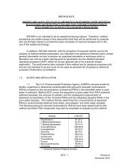
287METHOD <strong>2E</strong> - DETERMINATION OF LANDFILL GASPRODUCTION FLOW RATENOTE: This method does not include all of thespecifications (e.g., equipment and supplies) and procedures(e.g., sampling and analytical) essential to itsperformance. Some material is incorporated by referencefrom other methods in this part. Therefore, to obtainreliable results, persons using this method should also havea thorough knowledge of at least the following additionaltest methods: <strong>Method</strong>s 2 and 3C.1.0 Scope and Application.1.1 Applicability. This method applies to themeasurement of landfill gas (LFG) production flow rate frommunicipal solid waste landfills and is used to calculate theflow rate of nonmethane organic compounds (NMOC) fromlandfills.1.2 Data Quality Objectives. Adherence to therequirements of this method will enhance the quality of thedata obtained from air pollutant sampling methods.2.0 Summary of <strong>Method</strong>.2.1 Extraction wells are installed either in acluster of three or at five dispersed locations in thelandfill. A blower is used to extract LFG from thelandfill. LFG composition, landfill pressures, and orifice
288pressure differentials from the wells are measured and thelandfill gas production flow rate is calculated.3.0 Definitions. [Reserved]4.0 Interferences. [Reserved]5.0 Safety.5.1 Since this method is complex, only experiencedpersonnel should perform the test. Landfill gas containsmethane, therefore explosive mixtures may exist at or nearthe landfill. It is advisable to take appropriate safetyprecautions when testing landfills, such as refraining fromsmoking and installing explosion-proof equipment.6.0 Equipment and Supplies.6.1 Well Drilling Rig. Capable of boring a 0.61 m(24 in.) diameter hole into the landfill to a minimum of 75percent of the landfill depth. The depth of the well shallnot extend to the bottom of the landfill or the liquidlevel.6.2 Gravel. No fines. Gravel diameter should beappreciably larger than perforations stated in Sections 6.10and 8.2.6.3 Bentonite.6.4 Backfill Material. Clay, soil, and sandy loamhave been found to be acceptable.
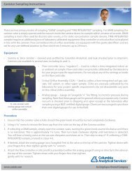
2896.5 Extraction Well Pipe. Minimum diameter of 3 in.,constructed of polyvinyl chloride (PVC), high densitypolyethylene (HDPE), fiberglass, stainless steel, or othersuitable nonporous material capable of transporting landfillgas.6.6 Above Ground Well Assembly. Valve capable ofadjusting gas flow, such as a gate, ball, or butterflyvalve; sampling ports at the well head and outlet; and aflow measuring device, such as an in-line orifice meter orpitot tube. A schematic of the aboveground well headassembly is shown in Figure <strong>2E</strong>-1.6.7 Cap. Constructed of PVC or HDPE.6.8 Header Piping. Constructed of PVC or HDPE.6.9 Auger. Capable of boring a 0.15- to 0.23-m (6-to 9-in.) diameter hole to a depth equal to the top of theperforated section of the extraction well, for pressureprobe installation.6.10 Pressure Probe. Constructed of PVC or stainlesssteel (316), 0.025-m (1-in.). Schedule 40 pipe. Perforatethe bottom two-thirds. A minimum requirement forperforations is slots or holes with an open area equivalentto four 0.006-m (1/4-in.) diameter holes spaced 90E apartevery 0.15 m (6 in.).6.11 Blower and Flare Assembly. Explosion-proofblower, capable of extracting LFG at a flow rate of
2908.5 m 3 /min (300 ft 3 /min), a water knockout, and flare orincinerator.6.12 Standard Pitot Tube and Differential PressureGauge for Flow Rate Calibration with Standard Pitot. Sameas <strong>Method</strong> 2, Sections 6.7 and 6.8.6.13 Orifice Meter. Orifice plate, pressure tabs,and pressure measuring device to measure the LFG flow rate.6.14 Barometer. Same as <strong>Method</strong> 4, Section 6.1.5.6.15 Differential Pressure Gauge. Water-filled U-tube manometer or equivalent, capable of measuring within0.02 mm Hg (0.01 in. H 2 O), for measuring the pressure of thepressure probes.7.0 Reagents and Standards. Not Applicable.8.0 Sample Collection, Preservation, Storage, andTransport.8.1 Placement of Extraction Wells. The landfillowner or operator may install a single cluster of threeextraction wells in a test area or space five equal-volumewells over the landfill. The cluster wells are recommendedbut may be used only if the composition, age of the refuse,and the landfill depth of the test area can be determined.8.1.1 Cluster Wells. Consult landfill site recordsfor the age of the refuse, depth, and composition of varioussections of the landfill. Select an area near the perimeter
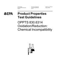
291of the landfill with a depth equal to or greater than theaverage depth of the landfill and with the average age ofthe refuse between 2 and 10 years old. Avoid areas known tocontain nondecomposable materials, such as concrete andasbestos. Locate the cluster wells as shown in Figure <strong>2E</strong>-2.8.1.1.1 The age of the refuse in a test area will notbe uniform, so calculate a weighted average age of therefuse as shown in Section 12.2.8.1.2 Equal Volume Wells. Divide the sections of thelandfill that are at least 2 years old into five areasrepresenting equal volumes. Locate an extraction well nearthe center of each area.8.2 Installation of Extraction Wells. Use a welldrilling rig to dig a 0.6 m (24 in.) diameter hole in thelandfill to a minimum of 75 percent of the landfill depth,not to extend to the bottom of the landfill or the liquidlevel. Perforate the bottom two thirds of the extractionwell pipe. A minimum requirement for perforations is holesor slots with an open area equivalent to 0.01-m (0.5-in.)diameter holes spaced 90E apart every 0.1 to 0.2 m (4 to8 in.). Place the extraction well in the center of the holeand backfill with gravel to a level 0.30 m (1 ft) above theperforated section. Add a layer of backfill material 1.2 m(4 ft) thick. Add a layer of bentonite 0.9 m (3 ft) thick,and backfill the remainder of the hole with cover material
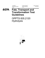
292or material equal in permeability to the existing covermaterial. The specifications for extraction wellinstallation are shown in Figure <strong>2E</strong>-3.8.3 Pressure Probes. Shallow pressure probes areused in the check for infiltration of air into the landfill,and deep pressure probes are use to determine the radius ofinfluence. Locate pressure probes along three radial armsapproximately 120E apart at distances of 3, 15, 30, and 45 m(10, 50, 100, and 150 ft) from the extraction well. Thetester has the option of locating additional pressure probesat distances every 15 m (50 feet) beyond 45 m (150 ft).Example placements of probes are shown in Figure <strong>2E</strong>-4. The15-, 30-, and 45-m, (50-, 100-, and 150-ft) probes from eachwell, and any additional probes located along the threeradial arms (deep probes), shall extend to a depth equal tothe top of the perforated section of the extraction wells.All other probes (shallow probes) shall extend to a depthequal to half the depth of the deep probes.8.3.1 Use an auger to dig a hole, 0.15- to 0.23-m (6-to 9-in.) in diameter, for each pressure probe. Perforatethe bottom two thirds of the pressure probe. A minimumrequirement for perforations is holes or slots with an openarea equivalent to four 0.006-m (0.25-in.) diameter holesspaced 90E apart every 0.15 m (6 in.). Place the pressureprobe in the center of the hole and backfill with gravel to
293a level 0.30 m (1 ft) above the perforated section. Add alayer of backfill material at least 1.2 m (4 ft) thick. Adda layer of bentonite at least 0.3 m (1 ft) thick, andbackfill the remainder of the hole with cover material ormaterial equal in permeability to the existing covermaterial. The specifications for pressure probeinstallation are shown in Figure <strong>2E</strong>-5.8.4 LFG Flow Rate Measurement. Place the flowmeasurement device, such as an orifice meter, as shown inFigure <strong>2E</strong>-1. Attach the wells to the blower and flareassembly. The individual wells may be ducted to a commonheader so that a single blower, flare assembly, and flowmeter may be used. Use the procedures in Section 10.1 tocalibrate the flow meter.8.5 Leak-Check. A leak-check of the above groundsystem is required for accurate flow rate measurements andfor safety. Sample LFG at the well head sample port and atthe outlet sample port. Use <strong>Method</strong> 3C to determine nitrogen(N 2 ) concentrations. Determine the difference between thewell head and outlet N 2 concentrations using the formula inSection 12.3. The system passes the leak-check if thedifference is less than 10,000 ppmv.8.6 Static Testing. Close the control valves on thewell heads during static testing. Measure the gaugepressure (P g ) at each deep pressure probe and the barometric
294pressure (P bar ) every 8 hours (hr) for 3 days. Convert thegauge pressure of each deep pressure probe to absolutepressure using the equation in Section 12.4. Record as P i(initial absolute pressure).8.6.1 For each probe, average all of the 8-hr deeppressure probe readings (P i ) and record as P ia (averageabsolute pressure). P ia is used in Section 8.7.5 todetermine the maximum radius of influence.8.6.2 Measure the static flow rate of each well onceduring static testing.8.7 Short-Term Testing. The purpose of short-termtesting is to determine the maximum vacuum that can beapplied to the wells without infiltration of ambient airinto the landfill. The short-term testing is performed onone well at a time. Burn all LFG with a flare orincinerator.8.7.1 Use the blower to extract LFG from a singlewell at a rate at least twice the static flow rate of therespective well measured in Section 8.6.2. If using asingle blower and flare assembly and a common header system,close the control valve on the wells not being measured.Allow 24 hr for the system to stabilize at this flow rate.8.7.2 Test for infiltration of air into the landfillby measuring the gauge pressures of the shallow pressureprobes and using <strong>Method</strong> 3C to determine the LFG N 2
295concentration. If the LFG N 2 concentration is less than5 percent and all of the shallow probes have a positivegauge pressure, increase the blower vacuum by 3.7 mm Hg(2 in. H 2 O), wait 24 hr, and repeat the tests forinfiltration. Continue the above steps of increasing blowervacuum by 3.7 mm Hg (2 in. H 2 O), waiting 24 hr, and testingfor infiltration until the concentration of N 2 exceeds5 percent or any of the shallow probes have a negative gaugepressure. When this occurs,reduce the blower vacuum to themaximum setting at which the N 2 concentration was less than5 percent and the gauge pressures of the shallow probes arepositive.8.7.3 At this blower vacuum, measure atmosphericpressure (P bar ) every 8 hr for 24 hr, and record the LFG flowrate (Q s ) and the probe gauge pressures (P f ) for all of theprobes. Convert the gauge pressures of the deep probes toabsolute pressures for each 8-hr reading at Q s as shown inSection 12.4.8.7.4 For each probe, average the 8-hr deep pressureprobe absolute pressure readings and record as P fa (thefinal average absolute pressure).8.7.5 For each probe, compare the initial averagepressure (P ia ) from Section 8.6.1 to the final averagepressure (P fa ). Determine the furthermost point from thewell head along each radial arm where P fa < P ia . This
296distance is the maximum radius of influence (R m ), which isthe distance from the well affected by the vacuum. Averagethese values to determine the average maximum radius ofinfluence (R ma ).8.7.6 Calculate the depth (D st ) affected by theextraction well during the short term test as shown inSection 12.6. If the computed value of D st exceeds thedepth of the landfill, set D st equal to the landfill depth.8.7.7 Calculate the void volume (V) for theextraction well as shown in Section 12.7.8.7.8 Repeat the procedures in Section 8.7 for eachwell.8.8 Calculate the total void volume of the test wells(V v ) by summing the void volumes (V) of each well.8.9 Long-Term Testing. The purpose of long-termtesting is to extract two void volumes of LFG from theextraction wells. Use the blower to extract LFG from thewells. If a single blower and flare assembly and commonheader system are used, open all control valves and set theblower vacuum equal to the highest stabilized blower vacuumdemonstrated by any individual well in Section 8.7. Every8 hr, sample the LFG from the well head sample port, measurethe gauge pressures of the shallow pressure probes, theblower vacuum, the LFG flow rate, and use the criteria forinfiltration in Section 8.7.2 and <strong>Method</strong> 3C to test for
297infiltration. If infiltration is detected, do not reducethe blower vacuum, instead reduce the LFG flow rate fromthe well by adjusting the control valve on the well head.Adjust each affected well individually. Continue until theequivalent of two total void volumes (V v ) have beenextracted, or until V t = 2 V v .8.9.1 Calculate V t , the total volume of LFG extractedfrom the wells, as shown in Section 12.8.8.9.2 Record the final stabilized flow rate as Q f andthe gauge pressure for each deep probe. If, during the longterm testing, the flow rate does not stabilize, calculate Q fby averaging the last 10 recorded flow rates.8.9.3 For each deep probe, convert each gaugepressure to absolute pressure as in Section 12.4. Averagethese values and record as P sa . For each probe, compare P iato P sa . Determine the furthermost point from the well headalong each radial arm where P sa < P ia . This distance is thestabilized radius of influence. Average these values todetermine the average stabilized radius of influence (R sa ).8.10 Determine the NMOC mass emission rate using theprocedures in Section 12.9 through 12.15.9.0 Quality Control.9.1 Miscellaneous Quality Control Measures.
298Section Quality Control Measure Effect10.1 LFG flow rate meterEnsures accuratecalibrationmeasurement of LFG flowrate and sample volume
29910.0 Calibration and Standardization.10.1 LFG Flow Rate Meter (Orifice) CalibrationProcedure. Locate a standard pitot tube in line with anorifice meter. Use the procedures in Section 8, 12.5, 12.6,and 12.7 of <strong>Method</strong> 2 to determine the average dry gasvolumetric flow rate for at least five flow rates thatbracket the expected LFG flow rates, except in Section 8.1,use a standard pitot tube rather than a Type S pitot tube.<strong>Method</strong> 3C may be used to determine the dry molecular weight.It may be necessary to calibrate more than one orifice meterin order to bracket the LFG flow rates. Construct acalibration curve by plotting the pressure drops across theorifice meter for each flow rate versus the average dry gasvolumetric flow rate in m 3 /min of the gas.11.0 Procedures. [Reserved]12.0 Data Analysis and Calculations.12.1 Nomenclature.AA avgA iA rC NMOC= Age of landfill, yr.= Average age of the refuse tested, yr.= Age of refuse in the ith fraction, yr.= Acceptance rate, Mg/yr.= NMOC concentration, ppmv as hexane(C NMOC = C t /6).C o= Concentration of N 2 at the outlet, ppmv.
300C t= NMOC concentration, ppmv (carbon equivalent)from <strong>Method</strong> 25C.C w= Concentration of N 2 at the wellhead, ppmv.D = Depth affected by the test wells, m.D st= Depth affected by the test wells in the shorttermtest, m.e = Base number for natural logarithms (2.718).f= Fraction of decomposable refuse in thelandfill.f i= Fraction of the refuse in the i th section.k = Landfill gas generation constant, yr -1 .L oL o '= Methane generation potential, m 3 /Mg.= Revised methane generation potential toaccount for the amount of nondecomposablematerial in the landfill, m 3 /Mg.M iM r= Mass of refuse in the ith section, Mg.= Mass of decomposable refuse affected by thetest well, Mg.P barP f= Atmospheric pressure, mm Hg.= Final absolute pressure of the deep pressureprobes during short-term testing, mm Hg.P fa= Average final absolute pressure of the deeppressure probes during short-term testing,mm Hg.P gf= final gauge pressure of the deep pressure
301probes, mm Hg.P gi= Initial gauge pressure of the deep pressureprobes, mm Hg.P i= Initial absolute pressure of the deep pressureprobes during static testing, mm Hg.P ia= Average initial absolute pressure of the deeppressure probes during static testing, mm Hg.P s= Final absolute pressure of the deep pressureprobes during long-term testing, mm Hg.P sa= Average final absolute pressure of the deeppressure probes during long-term testing,mm Hg.Q fQ i= Final stabilized flow rate, m 3 /min.= LFG flow rate measured at orifice meter duringthe i th interval, m 3 /min.Q s= Maximum LFG flow rate at each well determinedby short-term test, m 3 /min.Q t= NMOC mass emission rate, m 3 /min.R m = Maximum radius of influence, m.R ma = Average maximum radius of influence, m.R s= Stabilized radius of influence for anindividual well, m.R sa = Average stabilized radius of influence, m.t it t= Age of section i, yr.= Total time of long-term testing, yr.
302t vi= Time of the ith interval (usually 8), hr.V = Void volume of test well, m 3 .V r= Volume of refuse affected by the test well,m 3 .V t= Total volume of refuse affected by the longtermtesting, m 3 .V v = Total void volume affected by test wells, m 3 .WD = Well depth, m.D= Refuse density, Mg/m 3 (Assume 0.64 Mg/m 3 ifdata are unavailable).12.2 Use the following equation to calculate aweighted average age of landfill refuse.A avg' jNi'1 f iA iEq. <strong>2E</strong>-112.3 Use the following equation to determine thedifference in N 2 concentrations (ppmv) at the well head andoutlet location.Difference = C o - C w Eq. <strong>2E</strong>-212.4 Use the following equation to convert the gaugepressure (P g ) of each initial deep pressure probe toabsolute pressure (P i ).P i = P bar + P gi Eq. <strong>2E</strong>-3
30312.5 Use the following equation to convert the gaugepressures of the deep probes to absolute pressures for each8-hr reading at Q s .P f = P bar + P gf Eq. <strong>2E</strong>-412.6 Use the following equation to calculate thedepth (D st ) affected by the extraction well during theshort-term test.D st = WD + R ma Eq. <strong>2E</strong>-512.7 Use the following equation to calculate the voidvolume for the extraction well (V).2V = 0.40 B R ma D st Eq. <strong>2E</strong>-612.8 Use the following equation to calculate V t , thetotal volume of LFG extracted from the wells.V t' jNi'1 60 Q it viEq. <strong>2E</strong>-712.9 Use the following equation to calculate thedepth affected by the test well. If using cluster wells,use the average depth of the wells for WD. If the value ofD is greater than the depth of the landfill, set D equal tothe landfill depth.D = WD + R sa Eq. <strong>2E</strong>-812.10 Use the following equation to calculate thevolume of refuse affected by the test well.2V r = R sa B D Eq. <strong>2E</strong>-9
30412.11 Use the following equation to calculate themass affected by the test well.M r = V r D Eq. <strong>2E</strong>-1012.12 Modify Lo to account for the nondecomposablerefuse in the landfill.L o ' = f L o Eq. <strong>2E</strong>-1112.13 In the following equation, solve for k(landfill gas generation constant) by iteration. Asuggested procedure is to select a value for k, calculatethe left side of the equation, and if not equal to zero,select another value for k. Continue this process until theleft hand side of the equation equals zero, +0.001.k &keA avg&Q f2 L ) o M r' 0 Eq. <strong>2E</strong>-1212.14 Use the following equation to determinelandfill NMOC mass emission rate if the yearly acceptancerate of refuse has been consistent (+_10 percent) over thelife of the landfill.Q t' 2 L ) o A r (1 & e &kA ) C NMOC(3.595 x 10 &9 ) Eq. <strong>2E</strong>-13
30512.15 Use the following equation to determinelandfill NMOC mass emission rate if the acceptance rate hasnot been consistent over the life of the landfill.Q t' 2 k L ) o C NMOC (3.595 x 10&9 ) ' ni'1M ie &kt iEq. <strong>2E</strong>-1413.0 <strong>Method</strong> Performance. [Reserved]14.0 Pollution Prevention. [Reserved]15.0 Waste Management. [Reserved]16.0 References.1. Same as <strong>Method</strong> 2, Appendix A, 40 CFR Part 60.2. Emcon Associates, Methane Generation and Recoveryfrom Landfills. Ann Arbor Science, 1982.3. The Johns Hopkins University, Brown Station RoadLandfill Gas Resource Assessment, Volume 1: Field Testingand Gas Recovery Projections. Laurel, Maryland:October 1982.4. Mandeville and Associates, Procedure Manual forLandfill Gases Emission Testing.5. Letter and attachments from Briggum, S., WasteManagement of North America, to Thorneloe, S., <strong>EPA</strong>.Response to July 28, 1988 request for additionalinformation. August 18, 1988.6. Letter and attachments from Briggum, S., WasteManagement of North America, to Wyatt, S., <strong>EPA</strong>. Response to
306December 7, 1988 request for additional information.January 16, 1989.17.0 Tables, Diagrams, Flowcharts, and Validation Data.
307Figure <strong>2E</strong>-1. Schematic of Aboveground Well Head Assembly.
308PVC or HDPE Cap 4" (min) dia.2'PVC or HDPE Pipe 4" (min) dia.Ground Surface2'Existing Cover Material3'Bentonite SealCohesionless Backfill Material4'75% of theLandfill Depthand AboveLiquid LevelGravel No Fines 1 to 3" dia.Perforate 2/3 ofPipe LengthPVC or HDPE PipePVC or HDPE Cap 4" (min) dia.24" dia.WellboreFigure <strong>2E</strong>-3.Gas Extraction Well.
309Figure <strong>2E</strong>-2. Cluster Well Placement.
310X 150'X100'X 50'600'X 150'X100'X 50'600'XXXXXXXX 150'XXXXXX100'X 50'XXXXXX= Well= Shallow ProbeX = Deep ProbeFigure <strong>2E</strong>-4.Cluster Well Configuration.
311Quick Connect1" Cap1" PipeCover Material or EquivalentBentonite Seal1' - 6'4' (min)Sandy Loam orAppropriate Cover1'Gravel2/3 of ProbeLength6" to 9" Bore HoleFigure <strong>2E</strong>-5. Pressure Probe.
312