Composition of BÃHLER metal powders - Tenica
Composition of BÃHLER metal powders - Tenica
Composition of BÃHLER metal powders - Tenica

You also want an ePaper? Increase the reach of your titles
YUMPU automatically turns print PDFs into web optimized ePapers that Google loves.
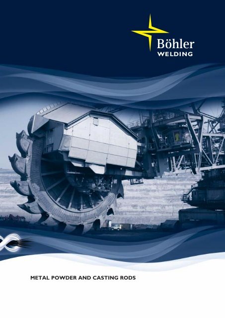
METAL POWDER AND CASTING RODS
ContentEverything under control: The know-how <strong>of</strong> <strong>metal</strong>lurgy, production technology and welding technology 4Hardfacing and thermal spraying 8Metal powder coating process 8■ Plasma transferred arc welding (PTA) 8■ Flame spray welding 10■ Flame spraying 12■ Plasma and high-velocity flame spraying (HVOF) 14Hardfacing process with casting rods 16■ Gas welding (O/A) 16■ TIG welding 17Typical properties <strong>of</strong> <strong>metal</strong> powder coatings and hardfacing 18<strong>Composition</strong> <strong>of</strong> BÖHLER <strong>metal</strong> <strong>powders</strong> 19Use <strong>of</strong> BÖHLER <strong>metal</strong> <strong>powders</strong> 20Deliverable grain sizes <strong>of</strong> BÖHLER <strong>metal</strong> <strong>powders</strong> 21<strong>Composition</strong> <strong>of</strong> BÖHLER casting rods 22Use <strong>of</strong> BÖHLER casting rods 23Deliverable dimensions <strong>of</strong> BÖHLER casting rods 24Reference values for weld <strong>metal</strong> hardness at room temperatureand for elevated temperature hardness <strong>of</strong> the pure weld <strong>metal</strong> 25Physical properties 26■ Thermal expansion 26■ Specific gravity, melting range and heat conductivity 26Properties <strong>of</strong> coatings with BÖHLER <strong>metal</strong> <strong>powders</strong> and casting rods 27Corrosion behaviour <strong>of</strong> BÖHLER <strong>metal</strong> <strong>powders</strong> and casting rods 28Application <strong>of</strong> BÖHLER <strong>metal</strong> <strong>powders</strong> and casting rods 29Practical tips regarding hardfacing 303
Everything under control:The know-how <strong>of</strong> <strong>metal</strong>lurgy,production technology and welding technologyFor more than 75 years the BÖHLER THYSSENSCHWEISSTECHNIK Deutschland GmbH has dealt withthe development and production <strong>of</strong> welding materials.An important application area <strong>of</strong> welding engineering isoverlay welding, e.g. to give a work piece surface a specialwear and/or corrosion resistance.BÖHLER <strong>of</strong>fers a wide range <strong>of</strong> gas atomized <strong>metal</strong> <strong>powders</strong>and casting rods on Co, Ni and Fe basis, which are suitablefor hardfacing and thermal spraying. These products aremanufactured to the highest standards.The starting point is the production <strong>of</strong> alloyed ingots manufacturedin our steel foundry. This enables us to use ourconsiderable experience gained over many years at an earlystage <strong>of</strong> production.Filling the liquid <strong>metal</strong> into the atomizing funnel.Temperature measurement during continuous casting.4
For the powder production the ingots are liquefied in aninduction furnace and brought to the gas atomization plant.The atomizing process is carried out in a closed containerwhere a stream <strong>of</strong> molten <strong>metal</strong> is atomized under highpressure with the aid <strong>of</strong> an inert gas, usually nitrogen. Withthis so-called gas atomization the speed <strong>of</strong> solidification is soslow that, during the time <strong>of</strong> the fall in the container, thedrops formed during atomization are transformed into balls.The globular form <strong>of</strong> the grains guarantees excellentflow behavior and thus, good controllability <strong>of</strong> the <strong>powders</strong>upply.Wind screening for the powder grain size.Continuous casting <strong>of</strong> the hardfacing rods.5
The powder is also precipitated under inert gas. This guaranteesthat the powder cools down without harmful surfaceoxidation. Low oxygen contents <strong>of</strong> the <strong>metal</strong> <strong>powders</strong> arethe result. It is necessary to screen the powder to the requiredgrain size before using the powder for spraying, plasmatransferred arc welding or sintering. This is done in modernscreening units or air separators.BÖHLER has a modern five-strand, horizontal continuouscasting machine for the production <strong>of</strong> hardfacing rods. Forthis production, the ingots have to be liquefied in an inductionfurnace the molten <strong>metal</strong> is then decanted into a“Tundish”. To reach the optimal weld ability <strong>of</strong> the qualities,the melt is washed during the process with shielding gas. Therods are straightened and then separated to the lengthrequested by the customer. On request the surface <strong>of</strong> therod can be ground.The <strong>metal</strong> <strong>powders</strong> and casting rods are subjected to extensivequality controls. For determination <strong>of</strong> the chemicalcomposition a laboratory with modern analytical equipmentis used. Equipment for carrying out screen analyses as wellas measurements <strong>of</strong> the flow rate, bulk density, hardness andmechanical technological properties is part <strong>of</strong> the standardequipment <strong>of</strong> the laboratory.Straightening the casting rods.6
Screen analyses instrument to determine the powder grain size.Optical emission spectrometer (OES) for thedetermination <strong>of</strong> the chemical analysis.View through a scanning electronmicroscope <strong>of</strong> gas atomizedspherical <strong>metal</strong> powder grains.7
Hardfacing and thermal sprayingMetal powder hardfacing processPlasma transferred arc welding (PTA)This method is a plasma welding process with a continuouspowder feeding. The powder feeding may be added separatelyas well as directly via the torch.carrier gas for the powder. The powder grains can pass intothe molten pool either in solid or molten form. This dependsupon the size, the shape and the quantity <strong>of</strong> the grains, thethermo-physical properties <strong>of</strong> the powder and the plasma,as well as upon the transfer time <strong>of</strong> the powder grains in theplasma.The arc is initiated between the tungsten electrode and theworkpiece. It is ignited and stabilized simultaneously with theaid <strong>of</strong> a pilot arc between the tungsten electrode and thecopper nozzle (anode). Main arc and pilot arc are suppliedindependently from their own power source. The tungstenelectrode is enveloped in argon as a centre gas. Within thearc, the argon is ionized forms a plasma with high beamenergy. Argon shielding gas is supplied via the outer nozzle.This shielding gas protects the molten pool against theingress <strong>of</strong> oxygen. The powder supply to the arc is carriedout via a mechanical metering device. Argon is used as aPlasma transferred arc welding has gained increasing significancein recent years. This process facilitates a build-up <strong>of</strong>powder alloys, which in the form <strong>of</strong> rods or wire, are difficultto produce or <strong>of</strong>ten cannot be produced. The advantages<strong>of</strong> plasma powder transferred arc welding is the preciseadjustment <strong>of</strong> the penetration depth and the build-up thickness(dilution) as well as the high energy density <strong>of</strong> the plasmaarc. Because <strong>of</strong> the continuous addition <strong>of</strong> powder, buildupwelds <strong>of</strong> uniformity and low porosity are produced sothat, in respect <strong>of</strong> mass production, a high degree <strong>of</strong> automationis possible.Tungsten electrodePlasma gas: Ar/Ar+H 2Copper anodeHFPowersourcepilot arcPilot arcMain arcBase materialArArPowder + Powder gasWaterPowersourceWatermain arcShielding gasWelding seamSchematic diagram<strong>of</strong> a torch for plasmatransferred arc welding.8
BÖHLER <strong>metal</strong> <strong>powders</strong> are used for hardfacing <strong>of</strong> bearingand sealing surfaces <strong>of</strong> gas, water, steam and acid fittings, alsovalve production for vehicle and shipping engines as well asfor highly stressed and wear resistant hardfacing onhotwork, crushing, stirring, extracting and drilling tools.The preheat and intermediate layer temperatures during theplasma transferred arc welding are dependant on the basematerial, the size <strong>of</strong> the workpiece and the number <strong>of</strong> layers.Plasma transferred arc welding <strong>of</strong> a continuous casting roll forsteel production.Plasma transferred arc welding(hardfacing <strong>of</strong> a sealing surface).9
Flame spray weldingFlame spray welding is a surface coating process. From ashort distance, via a torch the <strong>metal</strong> powder is sprayed ontothe base material and simultaneously fused. This producesfusion between the sprayed layer and the base materialcomparable to welding.With flame spray welding, the surface <strong>of</strong> the workpiece hasto be cleaned thoroughly <strong>of</strong> rust, grease and oil. The roughening<strong>of</strong> the <strong>metal</strong>lically clean surface should be effected byblasting or rough grinding in order to facilitate a good bond<strong>of</strong> the sprayed layer. Spraying should immediately be carriedout after surface preparation.This method is suitable for applying thin layers to smallareas, edges and repair work. Low and high alloy steels,stainless steels, cast steels, malleable cast iron, flake andspheroidal graphite cast iron can be sprayed. Powder basedon with additions <strong>of</strong> Cr-Si-B and powder-mix qualities areavailable.Flame spray welding with BÖHLER <strong>metal</strong> powder Niborit 4-P.Schematic representation <strong>of</strong> the flame spray welding.Acetylene oxygen mixturePowder containerSpraying powderLever forpowder supplyNozzleFlameOxygenAcetyleneCoatingBase materialAdjust oxygen supplyAdjust acetylene supply10
Flame spray welding with BÖHLER Niborit 5-P.11
Flame sprayingPowder flame spraying is a coating process, during which thespraying powder is melted by means <strong>of</strong> an oxy-fuel gas flameand sprayed onto the surface <strong>of</strong> the workpiece. This processis based upon a flame temperature <strong>of</strong> about 3,100 °C. Thepowder particles reach a speed up to 250 m/s, depending onparticle size, spraying distance and operational data <strong>of</strong> thespray gun. Whilst passing through the flame, the powderparticles should be in a melted and/or plastic condition.Powder flame spraying can be divided into two processes:■ Powder flame spraying without secondary thermaltreatment (cold spraying process)■ Powder flame spraying with subsequent fusing-in(melt fusion)With flame spraying the surface <strong>of</strong> the workpiece has to becleaned thoroughly <strong>of</strong> rust, grease and oil before the realbase preparation. The roughening <strong>of</strong> the <strong>metal</strong>lically cleanFlame spraying with theBÖHLER <strong>metal</strong> powder Niborit 6-P.12
surface should be made by blasting or rough grinding to facilitatea good bond with the sprayed layer. Spraying shouldimmediately be carried out after the surface preparation.With powder flame spraying without secondary thermaltreatment (called cold spraying process) a workpiece temperature<strong>of</strong> up to 300 °C is not exceeded, so that no changesin the structure <strong>of</strong> the component occur. With cold sprayingprocess, the problem <strong>of</strong> distortion is eliminated allconventional powder alloys used in industry can be sprayed.With the powder flame spraying process with subsequentfusing-in (called melt fusion), the applied <strong>metal</strong>lic sprayinglayers are subsequently sintered at temperatures <strong>of</strong> 1,000 to1,200 °C. The subsequent treatment can either be carriedout with the aid <strong>of</strong> torches, with furnaces or by induction.For these process variations only the so-called self-flowingalloys with a nickel base and cobalt base are used. Theirportions <strong>of</strong> boron and silicon aid the fusing process. Throughthis fusing process dense sprayed layers are produced andhave considerably improved properties in respect <strong>of</strong> homo-Flame spraying with BÖHLER <strong>metal</strong> powder Niborit 6-P.geneity, adhesion and surface roughness. Fields <strong>of</strong> applicationfor these powder flame spraying processes are to befound, in the chemical, glass, plastic and electrical industryas well as in machine, pump and compressor constructions.Powder flame spraying without secondary thermal treatment(cold spraying process)spraying powder onlySchematic representation<strong>of</strong> flame sprayingPowder flame spraying process with subsequent fusing-in(melt fusion)spraying powder afterwards fuse-in sprayed layer (sintering)13
Plasma and high-velocity flame spraying (HVOF)Plasma spraying belongs to the so-called arc sprayingprocesses. In a plasma torch, an electrical arc is ignited byhigh frequency between a water-cooled tungsten cathodelocated centrically and a water-cooled jet shaped copperanode. Gasses such as argon, helium, nitrogen or hydrogenor mixtures there<strong>of</strong> are forced under high pressure into thearc. The supplied gasses are ionized in the arc to plasma andreach temperatures up to 30,000 °C.This hot plasma flow leaves the torch nozzle with high speed(approx. 1,000 m/s) as a brightly glowing plasma beam.Powder + carrier gasCathodeAnodePowder injectorSprayed layerCooling waterPlasma gasPowderSpraying rayPlasma gas <strong>of</strong>Ar + H 2Ar + HePlasma gasPlasma flameCooling waterCurrent sourceBase materialSchematic representation<strong>of</strong> the plasma spraying.Entrance <strong>of</strong> powder+ propellantExpansion nozzleSprayed layerSpraying raySchematic representation<strong>of</strong> high-velocity flamespraying (HVOF).Mixing chamberCooling waterBase materialOxygenBurning gas (supporting flame)Burning gas(main flame)14
The spraying powder is added, by means <strong>of</strong> a conveying gas,in controlled doses to the plasma gas stream inside or outsidethe torch. In the plasma beam the spraying powder isaccelerated to very high speed (approximately 400 m/s),melted and shot onto the surface <strong>of</strong> the workpiece. Uponstriking the pretreated surface, the powder particles, whichhave become liquefied or plastic, form flat lamellas and solidifyat once. The plasma stream, rich in energy, and the highimpact speed <strong>of</strong> the powder particles upon the surface <strong>of</strong> theworkpiece, result in a dense, firmly adhesive spraying layers<strong>of</strong> high quality which has a lamellar structure.The outstanding difference between the conventional flamespraying and the high-velocity flame spraying (HVOF) is thehigh flow speed <strong>of</strong> the flame, which is above the speed <strong>of</strong>sound. A HVOF system consists <strong>of</strong> a spray gun, control unit,gas supply and a powder supply. The spray gun is the mainpart <strong>of</strong> the system. It consists <strong>of</strong> a gas mixing chamber,combustion chamber and an expansion nozzle. The sprayingpowder is supplied by the feeding system and is transportedcentrically by the conveying gas through the combustionchamber to the HVOF flame. The flame is formed using acombustible gas and oxygen mixture in a water-cooledpistol. Inside the expansion nozzle the powder particles areheated up and the powder particles are accelerated to veryhigh speeds. As in the case <strong>of</strong> plasma spraying, high-qualitysprayed layers are achieved, due to the high impact speed <strong>of</strong>the powder particles and the high-energy flame.When plasma and HVOF spraying, the surface <strong>of</strong> the workpiecehas to be cleaned carefully <strong>of</strong> rust, grease and oil, beforethe base preparation. The roughening <strong>of</strong> the <strong>metal</strong>licallyclean surface should be effected by blasting in order to facilitatea good bonding <strong>of</strong> the sprayed layer. The sprayingprocess should immediately be carried out after the surfacepreparation.The main areas <strong>of</strong> application <strong>of</strong> the plasma and HVOFspraying are protective layers against wear, corrosion, erosion,heat and abrasion and heat insulation, in the chemicalindustry, textile, paper and automobile industry, as well asin the construction <strong>of</strong> gas turbines, aircraft engines, ovens,pumps and reactors.Plasma spraying.15
Hardfacing process with casting rodsGas welding (Oxy-acethylene method)The gas welding process is carried out with the acetyleneoxygen flame. The chemical composition <strong>of</strong> the weld <strong>metal</strong>and the properties <strong>of</strong> the deposit are dependant on thecomposition <strong>of</strong> the welding rod and the dilution with thebase material.When gas welding, the base material is not melted butheated up to surface-fuse due to the low melting point <strong>of</strong> thehard alloys. Therefore the dilution with the base material isnegligibly small. It is usual to weld hard alloys with a reducingflame, which means with acetylene gas surplus, with aneutral flame, a thick oxide film would build up makingwelding difficult. A reducing flame adjustment, the flameconsists <strong>of</strong> three zones, the flame core, flame feather and theouter sheath <strong>of</strong> the flame. With an increasing acetylene gassurplus carbon is induced into the liquid weld pool. Thiscarbon can lead to strong carburizing and pore formation inthe weld <strong>metal</strong>. The carburizing <strong>of</strong> the weld <strong>metal</strong> also canincrease hardness <strong>of</strong> the overlay. To reduce or to avoidcarburizing and pore formation the hard alloys are weldedGas welding with the casting rod BÖHLER Celsit V.with the following flame adjustment: hard alloys on Co baseproportionally 3/1 (flame feather to flame core) and hardalloys on Ni base (Ni-Cr Si-B alloys) proportionally 2/1.Celsite (Co-Cr-W-C alloys)31Niborite (Ni-Cr-Si-B alloys)12Gas welding flameadjustment.16
TIG weldingIn the TIG welding process, a burnout <strong>of</strong> carbon or otheralloying elements doesn't occur because <strong>of</strong> the argon shieldinggas. The weld <strong>metal</strong> composition depends on thecomposition <strong>of</strong> the alloy used and the dilution with the basematerial. To keep the dilution with the base material as lowas possible it is recommended, to sharpen the tip <strong>of</strong> thetungsten electrode frustum shaped and not pointed as usual.This procedure avoids a strongly concentrated arc, whichwould cause much more melting <strong>of</strong> the base material andlead to a higher dilution with the welding material. Duringthe overlay process the arc has to be turned towards theliquid weld pool and not to the base material so that a lowerdilution can be achieved.The investigations on the mechanism <strong>of</strong> pore formationshowed, that during TIG welding the main cause lies in theoxygen content. The shielding gas (argon) prevents oxygenreaching the weld pool during welding. If pore formationtakes place, so this must be seen in connection with an oxidefilm (scale) <strong>of</strong> the base material and/or with an oxidation <strong>of</strong>the welding rod. Therefore it is important the base materialis cleaned sufficiently and the welding rod does not leavethe shielding gas too early.If necessary, the base material can get buffer layer beforehardfacing.TIG welding with the casting rodBÖHLER Celsit SN.17
Typical properties <strong>of</strong> <strong>metal</strong> powder coatingsand overlay weldingCoating and overlaywelding processLayer Thickness <strong>of</strong>coating (mm)Dilution(%)WorkpieceWarming upduring coatingDistortionafter coatingPlasma-transferred-arcwelding (PTA)2.0 - 6.0 per layer 5 - 20 high but locally highFlame spray welding up to 2.0 < 5 medium mediumFlame spraying (melt fusion) 0.5 - 2.0 0 high lowFlame spraying (cold spraying) 0.5 - 2.0 0 very low no distortionPlasma and HVOF-spraying up to 0.8 0 very low no distortionGas welding 1.5 - 5.0 per layer < 5 very high highTIG welding 1.5 - 5.0 per layer 10 - 30 high but locally high18
<strong>Composition</strong> <strong>of</strong> BÖHLER <strong>metal</strong> <strong>powders</strong>Grade Alloy type Typical analysis <strong>of</strong> the powder % by weightCobalt based C Si Cr Mo Ni W Fe B OthersCelsit V-P Alloy 6 1.1 28.0 4.5Celsit SN-P Alloy 12 1.4 30.0 8.5Celsit N-P Alloy 1 2.4 31.0 13.0Celsit 21-P Alloy 21 0.25 28.0 5.0 2.8Celsit FN-P Alloy F-mod. 1.6 1.0 28.0 22.0 13.0 1.0Celsit F-P Alloy F 1.8 26.0 23.0 12.5 1.0CN 20 Co 50-P Alloy 25 < 0.1 20.0 10.0 15.0Coborit 45-P Alloy SF 6 0.8 2.3 19.0 13.0 8.0 3.0 1.7 Cu 0.6Coborit 50-P 0.2 3.5 18.0 6.0 27.0 3.0Coborit 60-P Alloy SF 1 1.3 2.8 19.0 13.0 15.0 3.0Nickel based C Si Cr Mo Co W Fe B OthersNiborit 20-P 0.05 3.0 2.5 2.0Niborit 4-P Alloy 40 0.3 3.5 8.0 3.0 1.6Niborit 45-P Alloy 45 0.4 3.5 9.0 3.0 2.0Niborit 5-P Alloy 50 0.6 3.8 11.0 4.0 2.5SZW 5029 Alloy 56 0.6 4.0 12.5 4.0 2.8Niborit 6-P Alloy 60 0.8 4.3 16.0 4.5 3.5Niborit 7-P Alloy M 16C 0.50 3.7 17.0 4.5 2.0 3.75 Cu 2Nibasit Al 5-P NiAl 955
Use <strong>of</strong> BÖHLER <strong>metal</strong> <strong>powders</strong>Grade Alloy type Coating processCobalt based PTA FSS FSW FSK PS/HVOFCelsit V-P Alloy 6 ● ●Celsit SN-P Alloy 12 ● ●Celsit N-P Alloy 1 ● ●Celsit 21-P Alloy 21 ● ●Celsit FN-P Alloy F-mod. ● ●Celsit F-P Alloy F ● ●CN 20 Co 50-P Alloy 25 ● ●Coborit 45-P Alloy SF 6 ● ● ●Coborit 50-P ● ● ●Coborit 60-P Alloy SF 1 ● ● ●Nickel based PTA FSS FSW FSK PS/HVOFNiborit 20-P ● ● ● ●Niborit 4-P Alloy 40 ● ● ● ●Niborit 45-P Alloy 45 ● ● ● ●Niborit 5-P Alloy 50 ● ● ● ●SZW 5029 Alloy 56 ● ● ● ●Niborit 6-P Alloy 60 ● ● ● ●Niborit 7-P Alloy M 16C ● ● ● ●Nibasit Al 5-P NiAl 955 ●Nibasit Cr 20-P NiCr 8020 ●NiCr70Nb-P Nicro 82 ● ●Nibasit P 60-P Alloy Ni 60 ●Iron based PTA FSS FSW FSK PS/HVOFKW 10-P 1.4009 ● ● ●KW 40-P ● ● ●KWA-P 1.4015 ● ● ●SKWAM-P 1.4115 ● ● ●AS 4-P Alloy 316 ● ●AS 4-P/LC Alloy 316 L ● ●A7CN-P 1.4370 ● ●Antinit DUR 300-P●Ledurit 40-P ● ●Celsit SEO-P ● ●SZW 5033 Alloy E 6 ●Mixed <strong>powders</strong> PTA FSS FSW FSK PS/HVOFSuper DUR WC-P WSC-Ni/60-40 ●Super DUR W 6 Ni-P WSC-Ni/40-60 ● ●Coating processPTA: Plasma transferred arc weldingFSS: Flame spray weldingFSW: Flame spraying (melt fusion)FSK: Flame spraying (cold spraying)PS/HVOF: Plasma spraying /High-velocity flame spraying20
Deliverable grain sizes <strong>of</strong>BÖHLER <strong>metal</strong> <strong>powders</strong>Powder grain sizesfrom … up to (µm)Coating processesPTA FSS FSW FSK PS/HVOF20 – 45 ●20 – 106 ● ● ●32 – 106 ● ● ●45 – 90 ●45 – 125 ● ● ● ●50 – 150 ●50 – 160 ●50 – 180 ●63 – 150 ●63 – 160 ●63 – 180 ●63 – 200 ●Other grain sizes are available upon request.Packing is in plastic bottles in units <strong>of</strong> 5 or 9 kgor in tin buckets in units <strong>of</strong> 25 kg.Coating processPTA: Plasma transferred arc weldingFSS: Flame spray weldingFSW: Flame spraying (melt fusion)FSK: Flame spraying (cold spraying)PS/HVOF: Plasma spraying / High-velocity flame spraying21
<strong>Composition</strong> <strong>of</strong> BÖHLER casting rodsGrade Alloy type Typical analysis <strong>of</strong> the rod % by weightCobalt based C Si Cr Mo Ni W Fe B OthersCelsit V Alloy 6 1.1 1.3 27.0 1.0 4.5 1.0Celsit SN Alloy 12 1.8 1.3 29.0 1.0 8.5 1.0Celsit N Alloy 1 2.4 1.1 32.0 1.0 13.0 1.0Celsit 20 Alloy 20 2.2 32.0 1.0 16.5 1.0Celsit 21 Alloy 21 0.25 0.5 28.0 5.0 2.8 1.0Celsit F Alloy F 1.6 1.2 26.5 23.0 12.5 1.0CN 20 Co 50 Alloy 25 0.04 0.7 20.0 10.5 15.0 1.5 Mn 1.0SZW 6002 Alloy 4H 1.7 0.8 32.0 0.5 11.0 1.0SZW 6014 Alloy 12 AWS 1.45 1.2 29.0 0.5 8.5 1.0SZW 6043 Alloy T-400 0.08 2.4 8.5 27.5 1.5 1.5Nickel based C Si Cr Mo Co W Fe B OthersCelsit T-7 Alloy T-700 0.04 2.9 15.0 32.0 0.5 0.5SZW 36 Ni 60 0.8 3.6 16.0 17.0 Ni 61.0SZW 6026 Alloy 60-S<strong>of</strong>t 0.7 2.0 14.5 4.5 3.2SZW 6024 Alloy 60-Hard 0.75 2.0 14.5 4.0 3.8SZW 6037 Alloy 50 0.6 3.5 11.5 3.7 1.9Iron based C Si Cr Mo Ni W Co B OthersAntinit DUR 300 0.08 5.5 21.5 7.8
Use <strong>of</strong> BÖHLER casting rodsGrade Alloy type HardfacingOther applicationCobalt based Gas TIG Core wires DentalCelsit V Alloy 6 ● ● ●Celsit SN Alloy 12 ● ● ●Celsit N Alloy 1 ● ● ●Celsit 20 Alloy 20 ● ● ●Celsit 21 Alloy 21 ● ●Celsit F Alloy F ● ●CN 20 Co 50 Alloy 25 ● ● ●SZW 6002 Alloy 4H ● ●SZW 6014 Alloy 12 AWS ● ● ●SZW 6043 Alloy T-400 ●Nickel based Gas TIG Core wires DentalCelsit T-7 Alloy T-700 ●SZW 36 Ni 60 ●SZW 6026 Alloy 60-S<strong>of</strong>t ● ●SZW 6024 Alloy 60-Hard ● ●SZW 6037 Alloy 50 ● ●Iron based Gas TIG Core wires DentalAntinit DUR 300●Celsit SEO ● ●SZW 6046 Alloy E-6 ●Special alloys /dental alloysin Co and Ni base Gas TIG Core wires DentalSZW 6048 Spring-hard ●SZW 6049 Hard ●SZW 6050 Ceramic alloy ●SZW 6051 Ceramic alloy ●SZW 6052 Ceramic alloy ●SZW 6058 Hard ●RemarkHardfacing:Gas: Gas welding (oxyacetylene welding) / OTIG: Tungsten inert gas welding / WCore wires:Used with coated electrodesDental:Dental alloys for the production<strong>of</strong> dental casting23
Deliverable dimensions <strong>of</strong> BÖHLER casting rodsGraderod diameter in mmCobalt based 3.0 / 3.2 4.0 5.0 6.0 / 6.4 8.0Celsit V ● ● ● ● ●Celsit SN ● ● ● ● ●Celsit N ● ● ● ● ●Celsit 20 ● ● ● ●Celsit 21 ● ● ● ● ●Celsit F ● ● ● ● ●CN 20 Co 50 ● ● ● ●SZW 6002 ● ●SZW 6014 ● ● ● ● ●SZW 6043●Nickel based 3.0 / 3.2 4.0 5.0 6.0 / 6.4 8.0Celsit T-7●SZW 36●SZW 6026 ● ● ●SZW 6024 ● ● ●SZW 6037 ● ● ●Iron based 3.0 / 3.2 4.0 5.0 6.0 / 6.4 8.0Antinit DUR 300 ● ● ●Celsit SEO ● ● ● ●SZW 6046 ● ● ●Special alloys /dental alloysin Co and Ni base 3.0 / 3.2 4.0 5.0 6.0 / 6.4 8.0SZW 6048SZW 6049SZW 6050SZW 6051SZW 6052SZW 6058●●●●●●Rod lengths• Rods in standard manufacture are straightened and available in length <strong>of</strong> 300, 350, 400, 450, 500, 1,000 and 2,000 mm.• Dental alloys are available in length up to 2,000 mm.• Further lengths are available upon request.Rod surface• Rods in standard manufacture have a cast finish.• Ground rods are available upon request.24
Reference values for weld <strong>metal</strong> hardnessat room temperature and for elevatedtemperature hardness <strong>of</strong> the pure weld <strong>metal</strong>GradeHRCat RTelevated temperature hardness in HV 10 at …20 °C 100 °C 200 °C 300 °C 400 °C 500 °C 600 °C 700 °C 800 °C 900 °CCelsit V, ...V-P 41 410 394 344 330 322 311 272 197 180 152Celsit SN, ... SN-P 48 485 447 412 401 388 368 357 333 285 230Celsit N, ... N-P 53 626 605 571 523 487 451 445 386 304 263Celsit 20 56Celsit 21, ... 21-P 32 325 291 271 254 239 222 201 186 166 150Celsit FN-P 43Celsit F, ... F-P 45 446 442 400 355 333 315 304 295 271 228CN 20 Co 50, ... -P 230 HBCoborit 45-P 45 447 447 428 409 390 361 295 238 271Coborit 50-P 50Coborit 60-P 60 760 740 700 650 580 500 420 225SZW 6002 53SZW 6014 46SZW 6043 54Celsit T-7 47Niborit 20-P 42Niborit 4-P 40 400 388 377 366 344 285 222 120Niborit 45-P 45Niborit 5-P 50 540 515 471 447 420 380 280 138SZW 5029 55Niborit 6-P 60 740 674 657 626 580 502 368 170Niborit 7-P 62Nibasit Al 5-PBond layerNibasit Cr 20-P170 HBNiCr70Nb-P170 HBNibasit P 60-P240 HVSZW 36250 HVSZW 6026 54SZW 6024 58SZW 6037 50KW 40-P 44-55KWA-P 20-40SKWAM-P 30-55AS 4-P170 HBAS 4-P/LC170 HBA7CN-P170 HBAntinit DUR 300, ...-P 30 420 381 351 326 278Ledurit 40-P 43Celsit SEO, ... -P 57 650 650 650 526 428 435 335 238 222 141Super DUR WC-P > 60DUR W 6 Ni-P > 60RemarkThe hardness values given are valid for the alloy type independently <strong>of</strong> the product form or the coating processes.25
Physical propertiesThermal expansionGradeThermal expansion in 10 -6 m/m °Cat temperatures (°C)20-100 20-200 20-300 20-400 20-500 20-600 20-700 20-800 20-900Celsit V, ...V-P 11.9 13.5 14.0 14.4 14.7 15.3 15.8 16.0 16.1Celsit SN, ... SN-P 11.3 12.5 12.9 13.3 13.7 14.2 15.0 15.1 15.3Celsit N, ... N-P 11.1 11.6 12.3 12.8 13.0 13.3 14.0 14.4 14.6Celsit 21, ... 21-P 11.3 12.3 13.0 13.6 14.0 14.3 14.9 15.2 15.5Celsit F, ... F-P 11.5 12.6 13.0 13.2 13.5 13.9 14.5 14.9 15.4Coborit 45-P 9.7 10.8 11.9 12.3 12.8 13.4 13.8 14.1Coborit 60-P 11.5 13.6 14.2 14.9 15.2 15.5 15.9 16.7Niborit 4-P 11.4 12.7 12.9 13.3 13.5 13.9 14.5 14.9 15.4Niborit 5-P 11.4 12.1 12.2 12.5 12.7 12.9 13.4 13.8 14.2Niborit 6-P 11.0 11.6 12.0 12.3 12.5 12.8 13.1 13.5 14.0KW 40-P 10.5 11.0 11.0 11.5 12.0KWA-P 10.0 10.0 10.5 10.5 11.0SKWAM-P 10.5 11.0 11.0 12.0AS 4-P 16.5 17.5 17.5 18.5 18.5A7CN-P 18.0Antinit DUR 300, ...-P 15.7Celsit SEO, ... -P 11.3 12.5 13.1 13.3 13.5 13.6 14.4 14.5 14.5Specific gravity, melting range and heat conductivityGradeSpecific gravity Melting range Heat conductivityg/cm 3 °C °F W/mKCelsit V, ...V-P 8.30 1240 - 1340 2264 - 2444 15.0Celsit SN, ... SN-P 8.40 1220 - 1310 2228 - 2390 15.0Celsit N, ... N-P 8.70 1230 - 1290 2246 - 2354 15.0Celsit 21, ... 21-P 8.35 1360 - 1405 2480 - 2561Celsit F, ... F-P 8.40 1230 - 1290 2246 - 2354CN 20 Co 50, ... -P 9.15 1345 - 1395 2453 - 2543 10.5Coborit 45-P 8.30 1080 - 1150 1976 - 2102Coborit 50-P 8.30 1040 - 1120 1904 - 2048Coborit 60-P 8.40 1005 - 1210 1841 - 2210Niborit 4-P 8.20 1000 - 1150 1832 - 2102Niborit 45-P 8.20 990 - 1130 1814 - 2065Niborit 5-P 8.10 980 - 1070 1796 - 1958Niborit 6-P 7.90 960 - 1030 1760 - 1886KW 40-P 7.70 30.0KWA-P 7.70 1476 - 1501 2689 - 2734 25.0SKWAM-P 7.70 1435 - 1470 2615 - 2678 25.0AS 4-P 7.80 1412 - 1441 2574 - 2626 15.0A7CN-P 7.90 15.0Antinit DUR 300, ...-P 7.80 1360 - 1390 2480 - 2534Celsit SEO, ... -P 7.50 1230 - 1325 2246 - 241726
Properties <strong>of</strong> hardfacing and coatings withBÖHLER <strong>metal</strong> <strong>powders</strong> and casting rodsGradeAdhesivewearAbrasivewearImpactIntercrystallinestress Corrosion * corrosionHeatresistantHightemperatureresistantResistanceto thermalshocksMagneticCelsit V, ...V-P ● ● ● ● ● ● ●Celsit SN, ... SN-P ● ● ● ● ● ●Celsit N, ... N-P ● ● ● ●Celsit 20 ● ● ● ●Celsit 21, ... 21-P ● ● ● ● ● ● ●Celsit FN-P ● ● ● ● ● ●Celsit F, ... F-P ● ● ● ● ● ●CN 20 Co 50, ... -P ● ● ● ● ● ● ●Coborit 45-P ● ● ● ●Coborit 50-P ● ● ● ●Coborit 60-P ● ● ● ●SZW 6002 ● ● ● ● ● ●SZW 6014 ● ● ● ● ● ●SZW 6043 ● ● ● ● ● ● ● ●Niborit 20-P ● ● ● ● ●Niborit 4-P ● ● ● ● ●Niborit 45-P ● ● ● ●Niborit 5-P ● ● ● ● ●SZW 5029 ● ● ● ●Niborit 6-P ● ● ● ●Niborit 7-P ● ● ●Nibasit Al 5-P ● ●Nibasit Cr 20-P ● ● ●NiCr70Nb-P ● ● ● ● ● ●Nibasit P 60-P ● ● ● ● ●Celsit T-7 ● ● ● ● ● ● ● ●SZW 36 ● ● ● ● ●SZW 6026 ● ● ● ●SZW 6024 ● ● ● ●SZW 6037 ● ● ● ● ●KW 40-P ● ● ● ● ●KWA-P ● ● ● ● ● ●SKWAM-P ● ● ● ● ●AS 4-P ● ●AS 4-P/LC ● ● ●A7CN-P ● ● ●Antinit DUR 300, ...-P ● ● ● ● ● ● ●Ledurit 40-P ● ● ● ● ● ● ●Celsit SEO, ... -P ● ● ● ●SZW 5033 ● ● ● ● ● ●SZW 6046 ● ● ● ● ● ●Super DUR WC-P ● ●Super DUR W 6 Ni-P ● ●● = stable / yes*The corrosion resistance depends essentially on medium and temperature (see table on the next page).27
Corrosion behaviour <strong>of</strong> BÖHLER <strong>metal</strong> <strong>powders</strong>and casting rodsCorrosionmediumConcentration% by weightTemperature°CCelsit 21 Celsit V Celsit SN Celsit N Niborit 4 Niborit 6Phosphoric acid 10 RT 1 1 2H 3 PO 4 85 RT 1 1 210 65 1 1 4Nitric acid 10 RT 1 1 1 4 4HNO 3 70 RT 1 1 1 4 410 65 1 2 1 1 4 4Sulphuric acid 10 RT 1 1 1 1 3 2H 2 SO 4 90 RT 1 2 1 1 4 410 65 1 4 4 1 4 4Hydrochloric acid 5 RT 1 3 3 1 2HCL 37 RT 2 4 4 3-410 ST 4 4 4Acetic acid 20 RT 1 1 1CH 3 COOH 90 RT 1 1 130 ST 1 1 1 1 4 4Hydr<strong>of</strong>luoric acid 6 RT 4 4 2HF 40 ST 4Chromic acid 10 RT 1 1 110 ST 4 4 4Caustic soda lye 10 RT 1 1 1NaOH 40 RT 1 15 ST 1 1Copper chloride 2 RT 1 1CuCl 2 10 RT 1 1Ferric chloride 2 RT 1 1 1FeCl 3Ammonium nitrate 10 1 1NH 4 NO 3Strauss test 1 1 3 1 2RemarkRT: Room temperatureST: Boiling pointErosion rates1 = < 1 g/m 2 Day2 = 1-10 g/m 2 Day3 = 11-25 g/m 2 Day4 = > 25 g/m 2 Day28
Application <strong>of</strong> BÖHLER <strong>metal</strong> <strong>powders</strong>and casting rodsIndustryParts for hardfacing or coatingMetal powder or casting rodsAutomotive/VehicleengineeringEngine valves, seatsCelsit FN-P, Celsit F-P, Celsit V-P, Celsit SN-P,SZW 5033, Celsit FShipbuildingEngine valves, seats Celsit V-P, Celsit SN-P, Nibasit P 60-P, Celsit V,Celsit SN, Celsit T-7, SZW 36, SZW 6002,SZW 6024, SZW 6026, SZW 6043Glass industryPress-press/blow-press dies, die plates,press mouldsNiborit 4-P, Niborit 20-P, Niborit 45-PPower plantsValves, spindles, bushes, cones,other wear partsCelsit V-P, Celsit SN-P, Celsit 21-P, Celsit V,Celsit SN, Celsit 21,Antinit DUR 300-P, KWA-P,SKWAM-PPlastic industryBarrel extruders, bushesCelsit V-P, Celsit SN-P, Celsit N-P, Niborit 5-P,Celsit V, Celsit SN, Celsit NPumps/FittingengineeringSeat and guiding surfaces, cones, spindles,other wear partsCelsit V-P, Celsit SN-P, Celsit 21-P, KWA-P,SKWAM-P, Celsit V, Celsit SN, Celsit 21Wood/PaperindustryMotor saw rails, cutting rails and strips,cutting knifes, agitator bladesCelsit V-P, Celsit SN-P, Celsit N-P, Niborit 5-P,Niborit 6-P, Celsit V, Celsit SN, Celsit NSteel/MetalprocessingTransport rollers, guide rollers, hot shears,grates, rolling mill rollsCelsit V-P, Celsit SN-P, Celsit N-P, Celsit 21-P,Celsit SEO-P, Niborit 6-P, Coborit 60-P,Celsit V, Celsit SN, Celsit N, Celsit 21, Celsit SEOAgriculturalPlough blades, knifing discs, disc harrows Celsit SEO, Niborit 5-P, Niborit 6-P, Super DUR W-6 Ni-P, Super DUR WC-P, Celsit SEO, SZW 6024Cement/Mining/QuarryingHigh-pressure dies, worm conveyors,dredger teeth, single-blade cutters, crusher jaws,grinding bodies, wear platesNiborit 6-P, Celsit SEO-P, Super DUR WC-P,Super DUR 6 Ni-P, Celsit SEO, SZW 6024ChemistryBuffer materialBushes, seat surfaces, rotor shafts, bearing andsealing surfacesWhen hardfacing the crack formation has to bereduced by buffer layersAS4-P, Celsit 21-P, Celsit V-P, Celsit 21, Celsit VCN 20 Co 50-P, Celsit 21-P, NiCr70Nb-P, A7CN-P,CN 20 Co 50, Celsit 21Bond layerBond layer for thermal spraying Nibasit Al 5-P29
Practical tips regarding hardfacingProblemsCausesCountermeasuresLack <strong>of</strong> fusionLack <strong>of</strong> sidewallfusionWelding parameterSide walls too steeply, no radiusOptimization <strong>of</strong> the welding parameters.Flat position with sidewall angle 30 - 45 ° turnedwith radius <strong>of</strong> (R 1 - 3).DimensionalaccuracyShrinking ordistortionBase material delivered ready measured or littlerecord <strong>of</strong> detailed measures <strong>of</strong> the basematerial.High welding stresses, high welding andintermediate layer temperature, largernumber <strong>of</strong> layers.Edge construction (e.g. copper shoe), similarwelding material construction, buffering.Welding positioner, number <strong>of</strong> layers as less aspossible, low welding and intermediate layertemperature (if no cracks).Crack formationVery hard welding material, base material with alarge C content, low welding and intermediatelayer temperature, larger number <strong>of</strong> layers.Buffering, base material with a low C content,adjustment <strong>of</strong> the thermal expansions, high weldingand intermediate layer temperature, lower number<strong>of</strong> layers, suitable welding process.Hot crackformationOverheating <strong>of</strong> the weld pool, high welding andintermediate layer temperature, analyticalpollutions, unwanted trace elements.Prevent overheating, low welding and intermediatelayer temperature, no analytical pollutions, nounwanted trace elements.Pore formationOxide skin /Slag formationOverheating <strong>of</strong> the weld pool, analyticalpollutions, unwanted trace elements, flameadjustment, reactions to the gas formation.Base material surface containing scale, oxide andslag creator in the analysis (e.g.Al,Ti), shieldinggas not sufficient.No overheating <strong>of</strong> the weld pool, no analytical pollutions,no unwanted trace elements, optimal flameadjustment, no reactions to the gas formation.Metallically clean base material surface, no oxide orslag creators in the analysis, more shielding gas.Our technological department is at your disposal for further information or consultations.30
Several engine valves processed by hardfacing withBÖHLER <strong>metal</strong> <strong>powders</strong> and casting rods.
Published by BÖHLER WELDINGBöhler Thyssen Schweißtechnik Deutschland GmbHHansaalle 32140549 Düsseldorf / GERMANY+49 (0) 211-5378-0+49 (0) 211-5378-460postmaster@bsdg.dewww.boehler-welding.deMember <strong>of</strong> the BÖHLER-UDDEHOLM GroupBöhler Schweißtechnik Austria GmbHBöhler-Welding-St. 18605 Kapfenberg / AUSTRIA+43 (0) 3862-301-0+43 (0) 3862-301-95193postmaster.bsga@bsga.atwww.boehler-welding.comMember <strong>of</strong> the BÖHLER-UDDEHOLM GroupYour partner:BSGA 11/2005 E1000