Fuzzy Backing Control of Truck and Two Trailers
Fuzzy Backing Control of Truck and Two Trailers
Fuzzy Backing Control of Truck and Two Trailers

You also want an ePaper? Increase the reach of your titles
YUMPU automatically turns print PDFs into web optimized ePapers that Google loves.
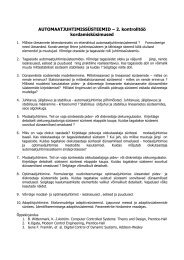
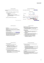
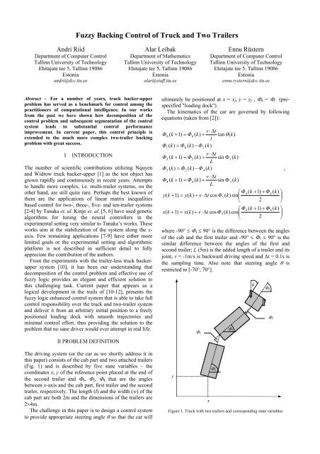
<strong>Fuzzy</strong> <strong>Backing</strong> <strong>Control</strong> <strong>of</strong> <strong>Truck</strong> <strong>and</strong> <strong>Two</strong> <strong>Trailers</strong>Andri Riid Alar Leibak Ennu RüsternDepartment <strong>of</strong> Computer <strong>Control</strong> Department <strong>of</strong> Mathematics Department <strong>of</strong> Computer <strong>Control</strong>Tallinn University <strong>of</strong> Technology Tallinn University <strong>of</strong> Technology Tallinn University <strong>of</strong> TechnologyEhitajate tee 5, Tallinn 19086 Ehitajate tee 5, Tallinn 19086 Ehitajate tee 5, Tallinn 19086Estonia Estonia Estonia<strong>and</strong>ri@dcc.ttu.ee alar@staff.ttu.ee ennu.rystern@dcc.ttu.eeAbstract – For a number <strong>of</strong> years, truck backer-upperproblem has served as a benchmark for control among thepractitioners <strong>of</strong> computational intelligence. In our worksfrom the past we have shown how decomposition <strong>of</strong> thecontrol problem <strong>and</strong> subsequent segmentation <strong>of</strong> the controlsystem leads to substantial control performanceimprovement. In current paper, this control principle isextended to the much more complex two-trailer backingproblem with great success.IINTRODUCTIONThe number <strong>of</strong> scientific contributions utilizing Nquyen<strong>and</strong> Widrow truck backer-upper [1] as the test object hasgrown rapidly <strong>and</strong> continuously in recent years. Attemptsto h<strong>and</strong>le more complex, i.e. multi-trailer systems, on theother h<strong>and</strong>, are still quite rare. Perhaps the best known <strong>of</strong>them are the applications <strong>of</strong> linear matrix inequalitiesbased control for two-, three-, five- <strong>and</strong> ten-trailer systems[2-4] by Tanaka et. al. Kinjo et. al. [5, 6] have used geneticalgorithms for tuning the neural controllers in theexperimental setting very similar to Tanaka’s works. Theseworks aim at the stabilization <strong>of</strong> the system along the x-axis. Few remaining applications [7-9] have either morelimited goals or the experimental setting <strong>and</strong> algorithmicplatform is not described in sufficient detail to fullyappreciate the contribution <strong>of</strong> the authors.From the experiments with the trailer-less truck backeruppersystem [10], it has been our underst<strong>and</strong>ing thatdecomposition <strong>of</strong> the control problem <strong>and</strong> effective use <strong>of</strong>fuzzy logic provides an elegant <strong>and</strong> efficient solution tothis challenging task. Current paper that appears as alogical development in the trails <strong>of</strong> [10-12], presents thefuzzy logic enhanced control system that is able to take fullcontrol responsibility over the truck <strong>and</strong> two-trailer system<strong>and</strong> deliver it from an arbitrary initial position to a freelypositioned loading dock with smooth trajectories <strong>and</strong>minimal control effort, thus providing the solution to theproblem that no sane driver would ever attempt in real life.II PROBLEM DEFINITIONThe driving system (or the car as we shortly address it inthis paper) consists <strong>of</strong> the cab part <strong>and</strong> two attached trailers(Fig. 1) <strong>and</strong> is described by five state variables – thecoordinates x, y <strong>of</strong> the reference point placed at the end <strong>of</strong>the second trailer <strong>and</strong> Φ 0 , Φ 2 , Φ 4 that are the anglesbetween x-axis <strong>and</strong> the cab part, first trailer <strong>and</strong> the secondtrailer, respectively. The length (l) <strong>and</strong> the width (w) <strong>of</strong> thecab part are both 2m <strong>and</strong> the dimensions <strong>of</strong> the trailers are2×4m.The challenge in this paper is to design a control systemto provide appropriate steering angle θ so that the car willultimately be positioned at x = x f , y = y f , Φ 4 = Φ f (prespecified"loading dock").The kinematics <strong>of</strong> the car are governed by followingequations (taken from [2]):v ⋅ ∆tΦ0( k + 1) = Φ0( k)+ tanθ( k)lΦ ( k)= Φ ( k)−Φ( k)1v ⋅ ∆tΦ2( k + 1) = Φ2( k)+ sin ΦLΦ ( k)= Φ ( k)−Φ( k)30224( k)v ⋅ ∆tΦ4( k + 1) = Φ4( k)+ sin Φ3( k)L⎛ Φ4( k + 1) + Φ4( k)⎞y(k + 1) = y(k)+ v ⋅ ∆tcosΦ3( k) sin⎜⎟⎝ 2 ⎠⎛ Φ4( k + 1) + Φ4( k)⎞x(k + 1) = x(k)+ v ⋅ ∆tcosΦ3( k) cos⎜⎟⎝ 2 ⎠where -90° ≤ Φ 1 ≤ 90° is the difference between the angles<strong>of</strong> the cab <strong>and</strong> the first trailer <strong>and</strong> -90° ≤ Φ 3 ≤ 90° is thesimilar difference between the angles <strong>of</strong> the first <strong>and</strong>second trailer; L (5m) is the added length <strong>of</strong> a trailer <strong>and</strong> itsjoint, v = -1m/s is backward driving speed <strong>and</strong> ∆t = 0.1s isthe sampling time. Also note that steering angle θ isrestricted to [-70°, 70°].yxFigure 1. <strong>Truck</strong> with two trailers <strong>and</strong> corresponding state variables1Φ 4Φ 2θΦ 0Φ 3Φ 1,
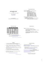
III CONTROL SYSTEM COMPONENTSIt was demonstrated in [10] that the control task <strong>of</strong> drivinga simple truck backwards to the loading dock can besolved with less effort if distinction between the tasks <strong>of</strong>trajectory planning <strong>and</strong> further determination <strong>of</strong> thesteering wheel angle that would force the car to follow aspecified trajectory, is made. Trajectory determination canbe carried out quite efficiently in indirect way by defininga desired car orientation angle (that in current applicationwould obviously apply to the second trailer angle Φ 4 ) foreach point in input space (x, y) <strong>and</strong> it was suggested in [10]that a simple fuzzy logic system called trajectorymanagement unit (TMU) can do the job. TMU actuallycomes in two parts – the upper one that defines carbehaviour for the positive (in respect to y) half plane (Fig.2) <strong>and</strong> lower one for the negative half plane (Fig. 3). Notethat sole reason for these blocks being implemented asseparate pieces is the need to cancel undesirable co-effectsfrom the interpolation <strong>of</strong> antagonistic rules. For the simpletruck navigation the task can then be completed bycomparing the desired orientation angle supplied by TMUwith the actual orientation <strong>of</strong> the car <strong>and</strong> this difference(i.e. orientation error) is supplied to the simple PDcontroller, which determines appropriate steering angle asa function <strong>of</strong> the error.However, as the experimentation with the truck <strong>and</strong>trailer system in [11] proved, things are not so simple anymore if we add a trailer to the truck because <strong>of</strong> the jointissue. The angle between the cab <strong>and</strong> trailer parts needs tobe manipulated if we expect any control performance <strong>and</strong>calls for a further segmentation <strong>of</strong> the control system.Interaction <strong>of</strong> the cab <strong>and</strong> trailer parts can be coordinatedby a joint controller, which in this case produces anoptimal angle between the cab <strong>and</strong> trailer partscorresponding to the (trailer) orientation error. Iforientation error ϕ is positive, the angle between the trailer<strong>and</strong> the cab (ξ) must also be positive (<strong>and</strong> vice versa) <strong>and</strong>thus the dependence must be monotonously increasing.This single-input single-output functional block isimplemented using fuzzy logic in order to obtain anonlinear mapping that is necessary to achieve expectedcontrol performance (Fig. 4). Finally, the differencebetween expected joint angle <strong>and</strong> its actual value will beused as an error function for the PD controller defining thesteering angle.Needless to say, in case <strong>of</strong> truck <strong>and</strong> two-trailer systemthings are even more complicated as there are two joints(<strong>and</strong> respective angles Φ 3 <strong>and</strong> Φ 1 that need to bemanipulated) because <strong>of</strong> what not one but two jointcontrollers have to be inserted into the control system. Firstone governs the relationship between orientation error Φ r4 -Φ 4 <strong>and</strong> expected Φ r3 , whereas the second one takes theinput from the first <strong>and</strong> compares it to the actual value <strong>of</strong>Φ 3 to produce desired Φ r1 . Error function for the PDcontroller will be computed by Φ r1 - Φ 1 . In summary, thisreasoning leads to the principal scheme <strong>of</strong> the controllerdepicted in Fig. 5.mf3mf2mf10-10 -5 0 5 10Figure 2. 15 TMU rules responsible for trajectory management wheny > 0. Each small arrow indicates optimal angle <strong>of</strong> the car correspondingto the given ruleξmf1 mf2 mf3 mf4 mf5If x is mf3 <strong>and</strong> y is mf2 thenΦ r is 90°mf1 mf2 mf3 mf4 mf5 mf6-15 -10 -5 0 5 10 15x604020Figure 3. Trajectory mapping unit (lower part)mf1 mf2 mf3 mf4 mf50-20-40-60If ϕ is mf1 then ξ is mf1If ϕ is mf2 then ξ is mf2If ϕ is mf3 then ξ is mf3If ϕ is mf4 then ξ is mf4If ϕ is mf5 then ξ is mf5-150 -100 -50 0 50 100 150ϕxFigure 4. Joint controller.252015105mf1mf2mf3mf4mf5y
xyΦ 4Φ 2Φ 0-16TMUΦ r4upperTMU0.40.3++yxΦ r4+-lowerTMU0.35JC1Φ r3+-JC2-+xyFigure 6. TMUΦ 4coordinatetransformationx ’ y ’x fy fΦ fΦ r1--+TMUΦ ’ r4PDangletransformationθΦ r4Figure 7. TMU interfaceFigure 5. <strong>Control</strong> system (principal scheme)IV CONFIGURING THE CONTROL SYSTEM.In order to achieve good control performance add-ons<strong>and</strong> further adjustments to the control system depicted inFig. 5 are required that will be explained in detail in thissection. First <strong>of</strong> all, we need to coordinate the cooperation<strong>of</strong> upper <strong>and</strong> lower TMUs with a switching block (Fig. 6)that will see to it that for positives values <strong>of</strong> y, Φ r4 will besupplied by upper TMU <strong>and</strong> for negative values by itsrespective counterpart. The effect from using hard limitersat the inputs <strong>of</strong> fuzzy systems is tw<strong>of</strong>old. First, they areabsolutely necessary to guarantee that input values arewithin the operating range <strong>of</strong> TMUs. Secondly <strong>and</strong> veryconveniently, these limiters also ensure that car navigationwill be governed by appropriate rules even when x <strong>and</strong> yappear to be outside <strong>of</strong> the scope <strong>of</strong> original TMUs.Scaling factors applied to the same inputs, on the otherh<strong>and</strong>, allow us to adjust the TMUs to the substantiallyincreased dimensions <strong>of</strong> the driving system (compared tothe single truck to which the TMUs have been originallyoptimized for) <strong>and</strong> with each other. Exactly the samereason calls for the corrective measure <strong>of</strong> -16 that will bededucted from the value <strong>of</strong> y fed to the upper TMU – itvirtually shifts the rules <strong>of</strong> the TMU higher so that there isenough space for the u-turn the car is required to makewhen returning from the negative half-plane.Secondly, fuzzy systems in Figs 2 <strong>and</strong> 3 are constructedunder the assumption that x f = 0, y f = 0, Φ f = 90°. In orderto save ourselves from redesigning these blocks each timethe position <strong>and</strong>/or the orientation <strong>of</strong> the loading dock ischanged, an interface is built between the actual values <strong>of</strong>x, y, Φ r4 <strong>and</strong> those that will be used for the computations inthe subsystem in Fig. 6 (which are denoted by x’, y’ <strong>and</strong>Φ’ r4 in Fig. 7).The values <strong>of</strong> x’ <strong>and</strong> y’ are obtained using the followingformulas:'ox = r cos(90 −Φf+ Φ4), (1)'oy = r sin(90 −Φf+ Φ4)wherer22= ( x − xf) + ( y − yf) . (2)Setpoint value corresponding to the given destination (x f ,y f , Φ f ) is computed by'oΦr 4= Φr4+ Φf− 90 . (3)In result, through all these adjustments, the TMU blockin Fig. 5 is updated to the current driving goal <strong>and</strong> physicalcharacteristics <strong>of</strong> the controlled object <strong>and</strong>, in a manner <strong>of</strong>speaking, generates a virtual force field in the driving areaas depicted in Fig. 8.
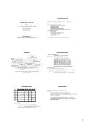
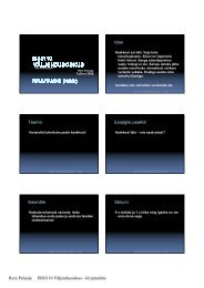
140JC2120Φ r3 - Φ 32.0JC -1.2Φ r110050y80Φ r10-5060-50 0 50Φ r3 - Φ 3Figure 8. "Force field", generated by TMUScaling factors come also very h<strong>and</strong>y for adjusting thejoint controllers. It can be deducted that for minimizing thedifference between Φ 4 <strong>and</strong> Φ r4 we need a negative angle <strong>of</strong>Φ 3 if Φ r4 - Φ 4 is positive (<strong>and</strong> vice versa), thus the functionperformed by the joint controller 1 should bemonotonously decreasing. This can be accomplished by anegative scaling factor on the respective controller output(Fig. 9). The same applies for the second joint controller -for minimizing the difference between Φ 3 <strong>and</strong> Φ r3 we needa negative angle <strong>of</strong> Φ 1 if Φ r3 - Φ 3 is positive (<strong>and</strong> viceversa). The absolute values <strong>of</strong> scaling factors, on the otherh<strong>and</strong>, enable us to impose limitations on Φ 1 <strong>and</strong> Φ 3 <strong>and</strong>specify sensitivity <strong>of</strong> joint controllers. It turns out that thefirst joint should be less receptive to control actions thatpropagate from the wheels <strong>of</strong> the cab <strong>and</strong> thus requireslower values for both scaling factors. In fact, appropriateselection <strong>of</strong> the output scaling factor value <strong>of</strong> first jointcontroller is critical to the overall control performance –even a small decrease e.g. a value <strong>of</strong> -0.8 leads toproportionally higher maximum values <strong>of</strong> Φ 3 that make thesystem unstable <strong>and</strong> jeopardize the control goal.Φ r4 - Φ 4Φ r340200-20-60 -40 -20 0 20 40JC10.8JC -0.5-50 0 50Φ r4 - Φ 4Figure 9. Joint controller No. 1xΦ r3Figure 10. Joint controller No. 2Finally, the block that translates the difference betweenΦ r1 <strong>and</strong> Φ 1 into appropriate steering angle θ is in thisapplication yet another scaling block (or a P-controllerwith K p = -3). The latter has a negative sign because weneed negative steering angle if Φ r1 - Φ 1 > 0 (<strong>and</strong> viceversa). Note that direct linear transformation is valid in therange [-23.3°, 23.3°] <strong>of</strong> Φ r1 - Φ 1 because <strong>of</strong> the physicalrestriction on θ.V RESULTSThis section presents the backing results from 10 r<strong>and</strong>omlyselected initial positions (Table I) to the loading docksituated at (x f = 0, y f = 70) with Φ f = 120°. In backing upthe truck <strong>and</strong> trailer systems there is one particularlyunfortunate position well known to drivers calledjackknife, which means that either Φ 3 or Φ 1 equals -90° or90°. In jackknife position car starts moving along a circle,never leaving it, never arriving to the loading dock<strong>and</strong>.thus becoming uncontrollable car. Since the jointcontrollers keep the values <strong>of</strong> Φ 1 <strong>and</strong> Φ 3 well under-90°/90°, it follows that whether the car goes to jackknifeor not, depends on the initial values <strong>of</strong> Φ 1 <strong>and</strong> Φ 3 only.With the help <strong>of</strong> selected simulations it was found outexperimentally that car goes jackknife if the absolutevalues <strong>of</strong> Φ 1 <strong>and</strong> Φ 3 both exceed 60° (if they have the samesign) or 50° (if they have different signs) <strong>and</strong> as aprecaution, in initial conditions the absolute values <strong>of</strong> Φ 1<strong>and</strong> Φ 3 are therefore kept below 45 degrees. <strong>Backing</strong>trajectories (for the sake <strong>of</strong> the clarity <strong>of</strong> the illustration,only the trajectory <strong>of</strong> the second trailer is drawn at each20 th sampling step) from these initial positions are depictedin Fig. 11. <strong>Backing</strong> quality is evaluated in terms <strong>of</strong> backingerrors (a weighted sum <strong>of</strong> distance <strong>and</strong> orientation errors atthe loading dock), computed byε = ε d+ 0. 0267ε Φ, (4)where⎪⎧2εd= ( xf− x(Tf)) + ( y⎨⎪⎩ εΦ= abs( Φf−Φ4( Tf))f− y(T ))f2, (5)where T f is the duration <strong>of</strong> the backing. These backingerrors for all 10 test drives are visualized in Fig. 12.
One must note that at current backing speed (1m/s) caradvances 10cm within one sampling interval, <strong>and</strong> thisuncertainty alone may be the reason why backing error isas high as 0.1 even if the car arrives at the loading dock atperfect angle. As it turns out, however, actual error valuesremain the within the range [0.1, 0.7]. When we recall thattotal length <strong>of</strong> the driving system is 12m, such inaccuracyis really marginal, besides, the backing trajectories appearto be very smooth. In order to demonstrate that suchcontrol quality is accomplished with minimal controlenergy, control action θ along with the dynamics <strong>of</strong> Φ 1 <strong>and</strong>Φ 3 for the one <strong>of</strong> the curviest backing trajectories (driveNo. 4) are depicted in Fig. 13.TABLE ITEST DRIVE INITIAL CONDITIONSNo. x(0) y(0) Φ 0 (0) Φ 2 (0) Φ 4 (0)1 28.3 124.9 115.2 145.7 103.22 18.1 21.8 345.6 357.2 340.43 29.4 138.8 268.0 277.7 294.24 -44.1 114.7 96.5 108.2 71.55 10.3 72.7 158.4 146.7 104.96 -45.0 79.8 336.0 342.8 352.97 -8.5 45.7 246.0 241.7 251.48 46.7 61.5 162.2 153.3 184.39 37.0 38.7 324.6 335.8 346.710 -49.0 43.0 2.0 23.0 43.8Φ 1,Φ 3θε0.060.040.02Figure 12. The backing results in terms <strong>of</strong> final positioning errors6040200-20-40Φ 1Φ 3-600 10 20 30 40 50t60 70 80 90806040200-20-4001 2 3 4 5 6 7 8 9 10drive No.-600 10 20 30 40 50 60 70 80 90tFigure 13. Angles Φ 1 <strong>and</strong> Φ 3 (above) <strong>and</strong> steering angle (below) duringthe backing (drive No. 4)14041 31201005y 8068604010dock97220-80 -60 -40 -20 0 20 40 60xFigure 11. The backing trajectoriesThough the control system is optimized for <strong>and</strong> theexperiments carried out at the fixed backing speed <strong>of</strong> 1m/s, it is capable <strong>of</strong> controlling the car at considerablyhigher speeds. It can be observed though that controlbecomes gradually less stable as speed increases. First sucheffects become apparent if speed reaches 5m/s <strong>and</strong> thoughthe car is still able to follow the trajectory to the loadingdock, the action at the steering wheel becomes more <strong>and</strong>more frantic from this point. The system becomescompletely uncontrollable if speed exceeds 10m/s. It is,however, highly doubtful if anyone has ever witnessed atwo-trailer truck storming backwards toward the loadingdock at such speeds in real life.VI CONCLUSIONSIn this paper we described a control system for the truck<strong>and</strong> two-trailer system, fully capable <strong>of</strong> steering the carfrom a virtually arbitrary initial position to the prespecifiedloading dock. Problem decomposition leads to ahierarchical control system that focuses on trajectorymanagement <strong>and</strong> subsequent trajectory-drivenmanipulation <strong>of</strong> trailer angles. These principal tasks arecarried out by very simple functional blocks implementedby the means <strong>of</strong> fuzzy logic, whereas additionalcomponents such as coordinate transformation blocks <strong>and</strong>scaling factors make the system easily reconfigurable <strong>and</strong>
extendable if the need arises. The main benefit fromproblem decomposition, however, is that it allows us todeal with resulting smaller problems individually thatultimately leads to the transparent control system withgood control performance <strong>and</strong> no loss in functionality.<strong>Fuzzy</strong> systems similarly benefit from having a smallnumber <strong>of</strong> input variables that keeps the number <strong>of</strong> fuzzyrules at a reasonably low level that is especially usefulwhen tuning the subsystems for best performance.The results strongly suggest that the control approachadopted in this paper could be further developed t<strong>of</strong>acilitate the control <strong>of</strong> trucks with even more trailers.[10] A. Riid <strong>and</strong> E. Rüstern, "<strong>Fuzzy</strong> logic in control: truckbacker-upper problem revisited," Proc. 10th IEEEInternational Conference on <strong>Fuzzy</strong> Systems,Melbourne, Vol. 1, 2001, pp. 513-516.[11] A. Riid <strong>and</strong> E. Rüstern, "<strong>Fuzzy</strong> Hierarchical <strong>Control</strong><strong>of</strong> <strong>Truck</strong> <strong>and</strong> Trailer," Proc. 8th Biennal BalticElectronic Conf., Tallinn, Estonia, 2002, pp. 141-144.[12] A. Riid <strong>and</strong> E. Rüstern, "Car Navigation <strong>and</strong>Collision Avoidance System with <strong>Fuzzy</strong> Logic",Proc IEEE International Conference on <strong>Fuzzy</strong>Systems, Budapest, Vol. 3, 2004, pp. 1443-1448.VII ACKNOWLEDGEMENTThis work was partially supported by the Estonian ScienceFoundation grant No. 6837.VIII REFERENCES[1] D. Nguyen <strong>and</strong> B. Widrow, "The truck backer-upper:An example <strong>of</strong> self-learning in neural network,"IEEE Contr. Syst. Mag., Vol. 10, No. 2, 1990, pp. 18-23[2] K. Tanaka, T. Taniguchi <strong>and</strong> H.O. Wang, "Modelbased<strong>Fuzzy</strong> <strong>Control</strong> for <strong>Two</strong>-<strong>Trailers</strong> Problem:Stability Analysis <strong>and</strong> Design via Linear MatrixInequalities," Proc. 6th IEEE Int. Conf. <strong>Fuzzy</strong> Syst.,Barcelona, Spain, 1997, pp. 343-348[3] K. Tanaka, S. Hori <strong>and</strong> H.O.Wang, "Multiobjective<strong>Control</strong> <strong>of</strong> a Vehicle with Triple <strong>Trailers</strong>,"IEEE/ASME Trans. Mechatronics, Vol. 7, No. 3,2002, pp. 357-368[4] K. Tanaka, T. Kosaki, H.O. Wang, "<strong>Backing</strong> <strong>Control</strong>Problem <strong>of</strong> a Mobile Robot with Multiple <strong>Trailers</strong>:<strong>Fuzzy</strong> Modeling <strong>and</strong> LMI-Based Design," IEEETrans. on Systems, Man <strong>and</strong> Cybernetics, Part C,Vol. 28, No. 3, 1998, pp. 329-337[5] B. Wang, H. Kinjo, K. Nakazono <strong>and</strong> T. Yamamoto,"Design <strong>of</strong> Backward Movement <strong>Control</strong> for a <strong>Truck</strong>System with <strong>Two</strong> <strong>Trailers</strong> Using NeurocontrollersEvolved by Genetic Algorithms," Transactions <strong>of</strong> theInstitute <strong>of</strong> Electrical Engineers <strong>of</strong> Japan, Vol. 123,No. 5, 2003, pp.983-990[6] E. Muh<strong>and</strong>o, H. Kinjo, E. Uezato <strong>and</strong> T. Yamamoto"Hybrid <strong>Control</strong>ler <strong>of</strong> Neural Network <strong>and</strong> LinearRegulator for Multi-trailer Systems Optimized byGenetic Algorithms," Proc. Int. Conf. <strong>Control</strong>,Automation <strong>and</strong> Systems, Gyeong Gi, Korea, 2005, 6pp.[7] D. F. Hougen, M. Gini, <strong>and</strong> J. Slagle, "RapidUnsupervised Connectionist Learning for <strong>Backing</strong> aRobot with <strong>Two</strong> <strong>Trailers</strong>", Proc. IEEE InternationalConference on Robotics <strong>and</strong> Automation, 1997, pp.2950-2955[8] B. Widrow <strong>and</strong> M.M. Lamego, "Neurointerfaces,"IEEE Transactions on <strong>Control</strong> Systems Technology,Vol. 10, No. 2, 2002, pp. 221-228[9] K. Alton <strong>and</strong> M. van de Pamme, "Learning to Steeron Winding Tracks Using Semi-Parametric <strong>Control</strong>Policies," Proc. International Conference on Robotics<strong>and</strong> Automation, Barcelona, Spain, 2005, 6 pp.