Kestrel Autopilot System - Unmanned Aircraft & Drones
Kestrel Autopilot System - Unmanned Aircraft & Drones
Kestrel Autopilot System - Unmanned Aircraft & Drones
- No tags were found...
You also want an ePaper? Increase the reach of your titles
YUMPU automatically turns print PDFs into web optimized ePapers that Google loves.
<strong>Kestrel</strong> <strong>Autopilot</strong> <strong>System</strong>ABSOLUTE MAXIMUM RATINGSInput Supply Voltage ..............................................-0.3V to 18VPayload Current........................................500mV @ 3.3V & 5VOperating Temperature Range ...........................-40ºC to 85ºCStorage Temperature Range.............................-40ºC to 125ºCMaximum Absolute Pressure........................................400 kPaMaximum Differential Pressure ....................................... 75kPaHumidity .........................................5% to 95%, no condensingAcceleration .................................................................... ±200 gStresses above those listed under the Absolute Maximum Ratingsmay cause permanent damage to the autopilot. This is a stressrating only; functional operation of the device at these or any otherconditions above those indicated in the operational section of thisspecification are not implied. Exposure to absolute maximum ratingconditions for extended periods may affect device reliability.OPERATING CHARACTERISTICSParameter Conditions Min Typ Max UnitsINPUT VOLTAGE (PWR)Operating Input Voltage RangeQuiescent Supply Current6.08015.5 VmAPayload POWER (Each Supply)3.3V Source5V SourceSupply CurrentAccuracyNoise3.35.0±0.515≈2.0500±2WVVmA%mV RMSAnalog Input Port5V Supply (V S ) Current5V Supply (V S ) NoiseInput Sample RangeInput Sample ResolutionPayload Serial & I/OLogic HighLogic LowCurrent (Sink & Source)Rate GyrosDynamic RangeFrequency Response (3dB Bandwidth)Resonant FrequencyAccelerometersDynamic RangeFrequency Response (3dB Bandwidth)Resonant FrequencyAttitude Estimation Error: Roll and PitchLevel FlightDuring TurnsDifferential Pressure: KAPv2.20, KAPv2.21RangeResolutionDifferential Pressure: KAPv2.22RangeResolutionAbsolute Pressure: KAPv2.20, KAPv2.21RangeResolutionAbsolute Pressure: KAPv2.22RangeResolutionAirspeed: KAPv2.20, KAPv2.21RangeResolutionAirspeed: KAPv2.22RangeResolutionAltitude: KAPv2.20, KAPv2.21RangeResolutionAltitude: KAPv2.22RangeResolutionDimensionsAccuracyWeightAccuracyV S = 4.95 VV S = 5 VT A = 25°C, V S = 5 V, Bandwidth = 9HzT A = 25°C, V S = 5 VT A = 25°C, V S = 5 VT A = 25°C, V S = 5 VT A = 25°C, V S = 5 VT A = 25°C, V S = 5 VT A = 25°C, V S = 5 V13 m/s (29 mph)T A = 25°C, V S = 5 V13 m/s (29 mph)T A = 25°C, V S = 5 VStandard atmospheric pressureT A = 25°C, V S = 5 VStandard atmospheric pressure02.3-0.25-1.3101.5111.300-13.7 (-45)-792 (-2,600)502.516 (0.0763)91422100.0001660.0005450.001150.002440.0076 (0.017)0.025 (0.056)0.116 (0.379)0.245 (0.804)2.073 x 1.375±0.516.65±450.46.8±300±105104.715.866.541.570 (156)130 (290)3414 (11,200)6,888 (22,600)mAmV RMSVbits (mV)VVmA°/sHzkHzgHzkHz°°kPakPakPakPakPakPakPakPam/s (mph)m/s (mph)m/s (mph)m/s (mph)m (ft)m (ft)m (ft)m (ft)inches%grams%www.procerusuav.com 801-224-57133
<strong>Kestrel</strong> <strong>Autopilot</strong> <strong>System</strong>PORT FUNCTIONSThe following tables describe the general pin assignments for each port type.Power PortPin Description1 GND2 PWR (6V – 18V)3 Current MonitorServo PortsPin Description1 PWR2 GND3 SignalOptional ADC PortPin Description1 GND2 PWR (3.3V or 5V)3 Ch 14 Ch 25 Ch 3Serial PortsPin Description1 GND2 PWR (3.3V or 5V)3 <strong>Autopilot</strong> TX4 <strong>Autopilot</strong> RX5 CMD or CLKPower Port: This port supplies the autopilot power and istypically connected directly to the autopilot or aircraft mainbattery. The GND and PWR pins connect to the negative andpositive battery terminal respectively. The Current Monitor pinis used to detect current draw of the main battery bymeasuring the voltage drop across a 0.01Ω resistor in serieswith the battery. This resistor’s power rating should be asfollows:RESISTOR POWER > (MAX MOTOR CURRENT) 2 x 0.01 (WATTS)Typical Current Monitor Circuit:TO BATTERY− TERMINALTO CURRENT MONITOR PINTO SPEED CONTROL− TERMINALpayload needs. The GPS port is dedicated for the GPS unit.The MODEM port is optional if the modem is not plugged intothe modem “piggy-back” header. For each serial port, theautopilot TX and RX lines are found on pins 3 and 4respectively. All serial ports operate at TTL levels (0V to3.3V) and can be configured for standard serial, SPI, or I 2 Ccommunication. Pin 5 on all serial ports serves as a digitalI/O. Pins 2 and 3 can be used as digital I/O if not being usedfor serial communication. Table 1 shows the pinassignments (connections to Rabbit 3000 processor) of allserial ports.Pin SerA SerE GPS Modem1 GND GND GND GND2 PWR (3.3V or5V)PWR (3.3V or5V)PWR (3.3V or5V)PWR (3.3V or5V)3 TxA (PC6) TxE (PG6) TxD (PC0) TxF (PG2)4 RxA (PC7) RxE (PG7) RxD (PC1) RxF (PG3)5 Reset/Smode ClkE (PG5) ClkD (PF0) TClkF (PG0)Table 1 - Serial Port Pin Descriptions0.01 ohmAnalog Input Port: Three analog inputs (pins 3-5) on theAnalog Input port allow users to measure 0.0V to 5.0V.Filtered analog 5V supply is available on pin 2. This pinsupplies the autopilot analog sensors so take caution not tointroduce noise on this pin. For specifications, see AnalogInput Port in the Operating Characteristics table.Serial & I/O Ports: There are 4 serial ports that double as I/Oports. Serial E and Serial A allow users to interface withServo Ports: These ports are configurable for differentaircraft types. Servo connections for standard configurationsare as follows:V-Tail ConfigurationPort Channel1 Right V-Tail2 Left V-Tail3 ThrottleElevon ConfigurationPort Channel1 Left Elevon2 Right Elevon3 Throttle4www.procerusuav.com 801-224-5713
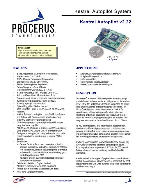
<strong>Kestrel</strong> <strong>Autopilot</strong> <strong>System</strong>KESTREL AUTOPILOTThe autopilot is the heart of the <strong>Kestrel</strong> system. It is powered by an 8-bit 29 MHz processor. The autopilot board contains a suite ofsensors used by the autopilot software to measure and estimate the states of the aircraft. The autopilot interfaces directly to thedigital communication link which enables it to send real-time status telemetry to the ground station and receive commands in-flight.The GPS plugs into the autopilot board (optional) and provides inertial navigation information to the autopilot. It also has severaladditional interface ports to support payloads. The autopilot controls the aircraft through four standard RC hobby servos. If moreservos are needed, a servo extender board can be used. Figure 1 shows the <strong>Kestrel</strong> autopilot with modem attached.6-DOFIMUAirspeedPortAltitudePortGPS portProgrammingand I/O portsServo Ports<strong>Autopilot</strong> Power andCurrent Measure PortModemAnalog input portFigure 1 - <strong>Kestrel</strong> 2.2 autopilot with Aerocomm AC4490 modem attached.ZYXRATE GYROS3ZYXACCELEROMETERS3ABSOLUTEPRESSUREDIFFERENTIALPRESSUREZYXRATE GYROSTEMERATURE3ADCADCSPI BUSSSPI BUSSPROCESSOR44SERVOPORTSSERIALPORTSOPTIAL ADCPORT3RCM3400PWRPORTSWITCHING REG.CIRCUIT+5V+3.3VFigure 2 - <strong>Kestrel</strong> 2.x block diagram.www.procerusuav.com 801-224-57135
<strong>Kestrel</strong> <strong>Autopilot</strong> <strong>System</strong>Port & LED LocationsTop View<strong>Aircraft</strong> FrontFigure 3 - Port and LED locations on the <strong>Kestrel</strong> 2.x autopilot. (2” x 1.37” x .47”)Jumper and Header LocationsTop View<strong>Aircraft</strong> FrontFigure 4 - Jumper and header locations on the <strong>Kestrel</strong> 2.x autopilot.6www.procerusuav.com 801-224-5713
<strong>Kestrel</strong> <strong>Autopilot</strong> <strong>System</strong><strong>Kestrel</strong> <strong>Autopilot</strong> v2.22Sensors and Attitude Estimation- Increased resolution on all sensors (8 x increase)- Acceleration measurements down to 1 mg- Roll and pitch estimation corrected for coriolis forces (10 - 25% improved roll and pitch estimates)- 2axis - magnetometer support - compass heading used to calibrate heading gyro on ground and in low ground speed situations.- Quicker sensor calibration and improved navigation, path following and altitude hold- Assist human pilot in speed and altitude mode (display on video)3-Sensor Temperature Compensation- 3 temperature sensors combined with 20 point temperature compensation algorithm significantly reduces sensor drift due totemperature changes. This reduces the need for the user to re-calibrate gyros and pressure sensors, aiding in sea or mobileoperations.Wind estimation- Real-time wind estimation algorithm relies on airspeed and GPS - continually updating estimate with latest wind data. Good to5% on wind speed and 2% on wind heading.Auto-trimThe autopilot can automatically fine tune UAV trim characteristics in the air. Trim values are then saved on the autopilot.Switching Voltage Regulation- The nominal regulator temperature remains constant over a broad range of input voltages. The maximum voltage input can beup to 18 volts. (KAPv2.x runs 50% cooler and draws 50% of the power compared to KAPv1.45)10g Accelerometers- 10g accelerometers now used vs 2g to better address vibration susceptibility in certain airframe configurations. The <strong>Kestrel</strong> canalso be configured with 2g sensors if desired.Mode support - single click autopilot configurations- Manual mode - rates only, activated by switch on RC controller- Speed mode - aircraft holds airspeed using pitch, (roll, airspeed, and throttle commands on ground station)- Altitude mode - aircraft holds altitude (roll, airspeed, and altitude commands from on ground station- Nav mode - aircraft navigates to standard and loiter waypoints- Home mode - aircraft flies home and loiters- Loiter now mode - aircraft loiters at current position- Take off modes (3) - aircraft uses preset commands to take off - automatically transitions to Nav mode at pre-set altitude- Land mode - aircraft flies to landing point on map and lands- Rally mode - aircraft flies to Rally pointMultiple user-configurable failsafes- Loss of communications- Loss of GPS lock- Low Battery and Critical Battery- Manual Modewww.procerusuav.com 801-224-57137
<strong>Kestrel</strong> <strong>Autopilot</strong> <strong>System</strong>Airframe Types Supported• V-tail• Elevon• Rudder, elevator• Rudder, elevator, aileron• Rudder, elevator, flapperon• Elevator, flapperon• Ruddervator, aileron8www.procerusuav.com 801-224-5713


