Stormwater Source Control Design Guidelines 2005 - Waterbucket
Stormwater Source Control Design Guidelines 2005 - Waterbucket
Stormwater Source Control Design Guidelines 2005 - Waterbucket

You also want an ePaper? Increase the reach of your titles
YUMPU automatically turns print PDFs into web optimized ePapers that Google loves.
<strong>Stormwater</strong> <strong>Source</strong> <strong>Control</strong><strong>Design</strong> <strong>Guidelines</strong> <strong>2005</strong>eaterancouveregionalstrictLanarc Consultants Ltd.Kerr Wood Leidal Associates Ltd.Goya NganFINAL REPORTApril <strong>2005</strong>
<strong>Stormwater</strong> <strong>Source</strong> <strong>Control</strong> <strong>Design</strong> <strong>Guidelines</strong> <strong>2005</strong>ContentsTable of ContentsForewordAcknowledgementsIntroduction .....................................................................1Summary Posters ..............................................................7Rainwater <strong>Source</strong> <strong>Control</strong> Around the World .....................17<strong>Design</strong> <strong>Guidelines</strong> .........................................................231. Absorbent Landscape........................................252. Infiltration Swale System ....................................333. Infiltration Rain Garden.....................................434. Pervious Paving ................................................535. Green Roof......................................................636. Infiltration Trench and Soakaway Manhole..........75<strong>Design</strong>, Construction and Maintenance Process .................81Candidate Plant List ......................................................119Glossary .....................................................................127Key Contacts ...............................................................133Key References .............................................................139Appendix A – Jurisdiction Summaries .............................. A-1Washington State ............................................... A-3Oregon ............................................................. A-7Australia .......................................................... A-12Europe ............................................................ A-17United Kingdom ............................................... A-19Germany ......................................................... A-24France............................................................. A-30Netherlands ..................................................... A-35Belgium........................................................... A-40Appendix B: Criteria for Choosing Priorities ......................B-1Greater Vancouver Sewerage & Drainage District
Contents <strong>Stormwater</strong> <strong>Source</strong> <strong>Control</strong> <strong>Design</strong> <strong>Guidelines</strong> <strong>2005</strong>List of FiguresFigure 1-1: <strong>Stormwater</strong> Variables of Absorbent LandscapeFigure 1-2: Interception, stemflow and throughfall dataFigure 1-3: Infiltration rate of a sandy loamFigure 5-1: Grain Size Distribution Range for SubstratesFigure F1: Typical 24 Hour Rainfall Depths in the GVRDFigure F2: Alternative <strong>Stormwater</strong> Treatment Chains for High DensityDevelopmentFigure F3: Alternative <strong>Stormwater</strong> Treatment Chains for Low DensityDevelopmentFigure F4: Example of Engineering PlanFigure F5: Example of Landscape PlanFigure F6: Example of Engineering Cross Section DetailFigure F7: Example of Landscape Cross Section DetailFigure F8: Example of Engineering ProfileFigure F9: Example of Landscape ProfileFigure A-1: Simplified Approach for <strong>Stormwater</strong> ManagementFigure A-2: Outflow OptionsFigure A-3: Cross-section – Swale-trench SystemFigure A-4: Comparison on Investment Costs and Project ValueFigure A-5: Street with Porous Pavement and Reservoir StructureFigure A-6: Networked Swale SystemFigure A-7: Shaft InfiltrationFigure A-8: Reconstructed and New EeuwkantenFigure A-9: Section of a Watercourse with Eeuwkanten in Auvergne PolderList of TablesTable 1-1: Typical Infiltration RatesTable 5-1: Weights of Common Building MaterialsTable F1: <strong>Stormwater</strong> <strong>Source</strong> <strong>Control</strong> <strong>Design</strong> ProcessTable F2: DFO <strong>Stormwater</strong> <strong>Guidelines</strong>Table F3: <strong>Stormwater</strong> Criteria from Provincial <strong>Stormwater</strong> GuidebookTable F4: Typical <strong>Stormwater</strong> <strong>Source</strong> <strong>Control</strong> ApplicationsTable F5: Typical Rainfall Capture TargetsTable F6: Tentative Match: <strong>Source</strong> <strong>Control</strong> Type to Soil Infiltration RateTable A-1: Example: Comparative present values of drainage system optionsTable A – 2: Space Required to Retain and Store WaterTable B-1: Criteria for Selection of Priority <strong>Stormwater</strong> <strong>Source</strong> <strong>Control</strong>sList of DrawingsDrawing 2A: Infiltration Swale Longitudinal ProfileDrawing 2B: Full Infiltration SwaleDrawing 2C: Full Infiltration Swale with ReservoirDrawing 2D: Partial Infiltration Swale with Reservoir and SubdrainDrawing 2E: Curbing OptionsDrawing 3A: Rain Garden - Full InfiltrationDrawing 3B: Rain Garden - Full Infiltration with ReservoirDrawing 3C: Rain Garden - Partial InfiltrationDrawing 3D: Rain Garden - Partial Infiltration with Flow RestrictorDrawing 3E: Flow Through PlanterDrawing 3F: Infiltration PlanterDrawing 4A: Pervious Paving - Full InfiltrationDrawing 4B: Pervious Paving - Partial InfiltrationDrawing 4C: Pervious Paving - Partial Infiltration with Flow RestrictorDrawing 5A: Multiple Layer Extensive Green RoofDrawing 5B: Multiple Layer Extensive Green Inverted RoofDrawing 5C: Single Layer Extensive Green RoofDrawing 6A, 6B, 6C: Sedimentation Manhole and Soakaway ManholesDrawing 6D: Infiltration TrenchGreater Vancouver Sewerage & Drainage District
<strong>Stormwater</strong> <strong>Source</strong> <strong>Control</strong> <strong>Design</strong> <strong>Guidelines</strong> <strong>2005</strong>ForewordForewordThis document represents the “Final” Release of Phase 1research results concerning <strong>Stormwater</strong> <strong>Source</strong> <strong>Control</strong> <strong>Design</strong><strong>Guidelines</strong> for the Greater Vancouver Regional District inBritish Columbia, Canada.In the spring of 2003, the Greater Vancouver Sewerage andDrainage District issued a proposal call for initial researchwork on <strong>Stormwater</strong> <strong>Source</strong> <strong>Control</strong> <strong>Design</strong> <strong>Guidelines</strong>. Acontract for Phase 1 of the work was established with aconsortium of landscape architects and engineers, including:Lanarc Consultants Ltd.Kerr Wood Leidal Associates Ltd.Goya Ngan, Landscape ArchitectAs required by the terms of reference, the production of <strong>Design</strong><strong>Guidelines</strong> was to be phased. Priorities for Phase OneResearch were set in consultation with the Client group. Onsubmission and review of an Interim Draft Report in the fall of2003, it was decided to extend the contract to complete a setof posters that publicized the results of the first phase work. Aset of six posters were produced.In winter 2004, the work was further reviewed by the<strong>Stormwater</strong> Interagency Liaison Group, a standing committeerepresenting local and regional governments, as well as seniorgovernment agencies. The work was well received, andcomments were made requesting further work.While this further work was arranged and completed, an‘Interim’ Release provided the benefit of the Phase 1 researchfindings to member municipalities of the GVRD.This report is the ‘Final’ release of the research findings. TheInterim Report is superceded by this Final Version. Primarychanges in the Final Version include additional chapters onInfiltration Trench and Shaft, a <strong>Design</strong> Process Chapter, and aweb-based Case Study module.Comments, or queries about the status of the research shouldbe directed to the Greater Vancouver Regional District, in thename of either:Mark Wellman, P. Eng., Greater Vancouver Regional DistrictMark.Wellman@gvrd.bc.caEd von Euw, P.Eng., Greater Vancouver Regional DistrictEd.vonEuw@gvrd.bc.caGreater Vancouver Sewerage & Drainage District
Acknowledgements <strong>Stormwater</strong> <strong>Source</strong> <strong>Control</strong> <strong>Design</strong> <strong>Guidelines</strong> <strong>2005</strong>AcknowledgementsIt is a rare opportunity as consultants to be given a mandate tosearch the world for design precedents and guidelines on anysubject – and even moreso when the subject has worldwideinnovation taking place – as is the case in stormwater sourcecontrols. The authors wish to recognize and thank the manyorganizations and individuals that provided their time andexperience to this project – listed below, in no order of priority:Lanarc Consultants Ltd.David Reid, FCSLA, Landscape Architect, Planner, PrincipalHarriet Rueggeberg, B.Sc., M.R.M., Environmental/ResourcePlannerDon Crockett, BCSLA, Landscape Architect, PrincipalDoug Backhouse, BCSLA, Landscape Architect, PrincipalNigel P.I. Gray, B.L.A., Landscape Architectural InternYongxu Yu, Landscape Architectural InternJana Zelenski, Landscape Architectural InternAlexe Lohvinen, Graphic <strong>Design</strong>erLinda Dawes, Library AssistantKerr Wood Leidal Associates Ltd.Chris Johnston, P.Eng.Crystal Campbell, P.Eng.Ken Ferraby, P.Eng.Troy Jones, P.Eng.Goya Ngan, Landscape ArchitectGreater Vancouver Regional District (Client)Robert Hicks, P.Eng.Ed von Euw, P.Eng.Mark Wellman, P.Eng.Hugh Kellas, FCIP<strong>Stormwater</strong> Interagency Liaison GroupIn particular, we would also like to express our gratitude to themany experts around the world that we contacted – either as apart of this research project or in advance – who gave freely oftheir time and expertise to help us understand that current stateof the art in stormwater source controls. For those listed in theContact List in the body of this report, we give our thanks.We hope to be able to share this Report with many of those onthe Contact List – and would value whatever additionalcomments or direction that they could offer.Thank you.Greater Vancouver Sewerage & Drainage District
<strong>Stormwater</strong> <strong>Source</strong> <strong>Control</strong> <strong>Design</strong> <strong>Guidelines</strong> <strong>2005</strong>IntroductionINTRODUCTIONGreater Vancouver Sewerage & Drainage District1
Introduction <strong>Stormwater</strong> <strong>Source</strong> <strong>Control</strong> <strong>Design</strong> <strong>Guidelines</strong> <strong>2005</strong>This page is intentionally left blank.2Greater Vancouver Sewerage & Drainage District
<strong>Stormwater</strong> <strong>Source</strong> <strong>Control</strong> <strong>Design</strong> <strong>Guidelines</strong> <strong>2005</strong>IntroductionThe ProjectThe objective of this project is to reduce information barriersthat stand in the way of effective implementation of stormwatersource controls in the Greater Vancouver Regional District. Itfocuses on the technical details of practices in landscape areasthat treat stormwater through plant materials and soils byinfiltration, retention, detention and evapotranspiration.The Greater Vancouver Regional District (GVRD) providesregional government services to its member municipalities,and is the third largest metropolitan area in Canada. A relatedbody, the Greater Vancouver Sewerage & Drainage District(GVSDD), provides regional utility services. In 1999, theGVSDD produced a Best Management Practices Guide for<strong>Stormwater</strong>, which can be viewed athttp://www.gvrd.bc.ca/sewerage/management_guide.htm.<strong>Stormwater</strong> - Rainwater‘<strong>Stormwater</strong> management’ is the term traditionally used –mostly in North America - to refer to managing rainfall runoffusing conventional “storm-based” approaches to sizing anddesigning drainage facilities. Urban design thinking hasevolved, however, to address the entire spectrum of rainfallevents, not just storms, in ways that reflect more natural watersystems. ‘Rainwater management’ – generally used in Europe- more accurately describes this more holistic approach.This document uses the more familiar term ‘stormwater’ withthe intent that it refers to the broader scope of ‘rainwater’management.Vancouver, British Columbia, Canada is aworld-class city framed by the coastalmountains, the estuary of the Fraser River,and the sea.Greater Vancouver Sewerage & Drainage District3
Introduction <strong>Stormwater</strong> <strong>Source</strong> <strong>Control</strong> <strong>Design</strong> <strong>Guidelines</strong> <strong>2005</strong>The <strong>Source</strong> <strong>Control</strong>sIn 2003, a team of consulting engineers and landscapearchitects was commissioned by the GVSDD to createtechnical design guidelines for a selection of these BestManagement Practices that related to stormwater sourcecontrol. The team compiled technical literature from regionsof the world that have climates similar to Vancouver on thefollowing source control topics: Absorbent landscapes, including native soils and woods,compost-amended soils, planters and other treatments toreduce runoff from landscape areas; Bioretention facilities, which can include rain gardens,sunken landscape areas, and infiltration areas, with orwithout an underdrain; Vegetated swales, including bioswales and associatedvegetated filter strips; Pervious paving, including both vegetated andunvegetated types; Infiltration trenches, sumps and drywells, including variousunderground infiltration devices; and Extensive green roofs.The InformationOf particular interest were technical standards or designguidelines that are supported by government agencies orindustry associations. The research aimed to acquire atechnical level of detail appropriate to a ‘typical designstandard’ that is suitable for testing, and which can beadapted to a given site or context by design professionals –specifically: <strong>Source</strong> control application, performance, scale, sitesuitabilityand limitations; Generalized material specifications; Consideration of material availability, complexity andcosts of construction and maintenance of the technique; Typical construction drawings as appropriate; Candidate plant species, maintenance requirements andrelated aspects; and Any relevant guidelines, standards, drawings or images ofthe specified source control.4Greater Vancouver Sewerage & Drainage District
<strong>Stormwater</strong> <strong>Source</strong> <strong>Control</strong> <strong>Design</strong> <strong>Guidelines</strong> <strong>2005</strong>IntroductionThe ProductsThe project has two groups of products: A review of technical literature on source controls and theiruse from jurisdictions with climates similar to Vancouver,including the Pacific Northwest, Germany, theNetherlands, Belgium, France, the United Kingdom, andparts of Australia and New Zealand. Some aspects ofdocuments have been translated into English. The specificproducts are:− Written literature assembled into a set of bindersorganized under the six source control topics. Thesebinders are available for viewing at the library of theGreater Vancouver Regional District, in Burnaby, B.C.− A report that reviews the status of stormwatermanagement, key concepts, source controls in use andcase studies from each jurisdiction. A summary of thereport is contained in Part 2 of this document, and thefull report is presented in Appendix A. <strong>Design</strong> guidelines applicable to Greater Vancouver forselected best management practices (prioritized inAppendix B), including typical details, general specifications,and guidelines for use. These are presented in twoformats:− A series of posters that presents a summary of thejurisdictional study and the key features of each of thesource controls in a highly illustrated and user-friendlymanner.− A report - Part 3 of this document - that discusses theapplication, limitations, functions, design guidelinesand specifications for each of the six priority sourcecontrol topics.The intent is that these posters and report files will be adaptedto web delivery as well, so that the information can be madeaccessible to a wide audience of engineers, landscapearchitects, architects, planners, developers, builders, inspectorsand universities.However, these design guidelines are not intended to be usedas detail designs. Proper site investigation and site-specificdesigns by appropriate professionals that comply withapplicable laws, bylaws or regulations are required. Thesedesign guidelines can provide guidance and inspiration oninnovative means of achieving stormwater managementobjectives.Greater Vancouver Sewerage & Drainage District5
Introduction <strong>Stormwater</strong> <strong>Source</strong> <strong>Control</strong> <strong>Design</strong> <strong>Guidelines</strong> <strong>2005</strong>This page is intentionally left blank.6Greater Vancouver Sewerage & Drainage District
<strong>Stormwater</strong> <strong>Source</strong> <strong>Control</strong> <strong>Design</strong> <strong>Guidelines</strong> <strong>2005</strong>Summary PostersSUMMARY POSTERSGreater Vancouver Sewerage & Drainage District7
Summary Posters <strong>Stormwater</strong> <strong>Source</strong> <strong>Control</strong> <strong>Design</strong> <strong>Guidelines</strong> <strong>2005</strong>Summary PostersThe applied research regarding stormwater source controls isonly effective if the information is communicated to usergroups.To reach the target audience of design professionals,developers, construction management and approval agencystaff, a series of technical posters have been produced tointroduce the research results.Reduced versions of the posters are printed on the followingpages. Mid-size (A3 - 11 x 17 inch) versions are available fordownload through the GVRD website, athttp://www.gvrd.bc.ca/sewerage/stormwater_reports.htm .Full size (A1 – 24 x 36 inch) versions of the posters may alsobe available by special arrangement with the GVRD.8Greater Vancouver Sewerage & Drainage District
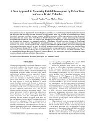
S RAustraliaaBelgiumBritish ColumbiaFranceGermanyNetherlandsOregon StateUnited KingdomWashington State400,000 sq.m of permeablepaving block designs weresold in 2001. Research isshowing that microbes inrock base courses treat oilentering the pavement.Dutch wadis are broadvegetated swales that fill withwater during heavy rainfallsand then drain in about 24hours.UNITED KINGDOM"Sustainable Urban Drainage Systems" (SUDS)use "Soakaway" methods such as rock pits, drywells and infiltration trenches.NETHERLANDSInfiltration trenches, green roofsand permeable pavement arecommon. Flood storage on roadsis allowed, but not on bikeways!GERMANYIn use for over 30 years, about 1 in7 of new flat roofs are green roofs- 13.5 million sq.m in 2001. Mostcities reduce stormwater feeswhen source controls are used.A swale /trench system reducesstormwater volumes to 1/10thof a conventional system,saving 30% in stormwater fees.WASHINGTON"Low Impact Development" (LID)techniques try to preserve'natural' watershed characteristics.<strong>Stormwater</strong> manuals haveprovided guidance since 1992.Seattle’s "Street EdgeAlternatives" (SEA) projectcaptures 98% of the wetseason runoff - beautifully.AUSTRALIAAustralia uses "Water Sensitive Urban<strong>Design</strong>" (WSUD) to maximize on-siteretention, infiltration, treatment andre-use-even in clay soils. Aquifer storageand recovery is widely used.Rainwater reuse on this site reducesthe consumption of water from themain system by 77%.BELGIUMSome municipalities offer subsidies forsource controls; e.g., Mortsel pays $5.60/sq.m for green roofs and 50% of the costof an infiltration system.FRANCESwales ("noues") are valued as visiblestormwater treatment. Porouspavements are used both as a sourcecontrol and to reduce traffic noise.The grate leads to an undergroundgeo-membrane lined trench filledwith sand and pebbles that filtersparticles and allows infiltration.Excess water flows to further settlingand filtration systems.BRITISH COLUMBIA/CANADAPolicies supporting source controls havebeen in the works since the 1990’s. Pilotprojects with source controls have beencompleted and monitoring is on-going.Implementation is accelerating.Over 600 green roof installationsexist in Coastal BC, including thismonitored Green Roof at theVancouver Library.Buckman Terrace Apartments inPortland uses source controls toavoid runoff into combinedsewers.OREGONPortland provides "tree credits" instormwater calculations, and also offersan "eco-roof density bonus" as a greenroof incentive.Precedents Around the WorldGreaterVancouverRegionalDistrict<strong>Stormwater</strong> <strong>Source</strong> <strong>Control</strong> <strong>Design</strong> <strong>Guidelines</strong> <strong>2005</strong>Goya NganLandscape ArchitectDetailed design guidelines can be found in the <strong>Design</strong><strong>Guidelines</strong> <strong>2005</strong> report, available at www.gvrd.bc.ca9
DESIGN PRINCIPLES■ Maximize the area of absorbentlandscape – either existing orconstructed – on the site. Conserveas much existing vegetation andundisturbed soil as possible.■ Minimize impervious area by usingmulti-storey buildings, narrowerroads, minimum parking, largerlandscape areas, green roof, andpervious paving.■ Disconnect impervious areas fromthe storm sewer system, havingthem drain to absorbent landscape.■ <strong>Design</strong> absorbent landscape areasas dished areas that temporarilystore stormwater and allow it to soakin, with overflow for large rain eventsto the storm drain system.15% CrownInterception8% Stemflow77% ThroughfallPear TreeWinter tree canopies intercept15% to 27% of rainfall.27% CrownInterception15% Stemflow58% ThroughfallEvergreen Oak Tree13In most natural wooded conditions inthe GVRD, 90% of rainfall volumenever becomes runoff, but is eithersoaked into the soils or evaporates /transpirates. Trees, shrubs, grasses,surface organic matter, and soils allplay a role.Variables of Absorbent Landscape1. Crown Interception2. Throughfall and Stemflow3. Evapotranspiration4. Soil Water Storage5. Soil Infiltration6. Surface Vegetation7. Organics and Compost8. Soil Life9. Interflow10. Deep Groundwater11. Water Quality Improvement12. Impermeable Surfaces andSurface Runoff■ Maximize the vegetation canopycover over the site. Multi-layeredevergreens are ideal, but deciduouscover is also beneficial forstormwater management.■ Ensure adequate growing mediumdepth for both horticultural andstormwater needs – a minimum150mm for lawn areas, and 450mmdepth for shrub/tree areas. In wetterclimates with till subsoils, a minimumdepth of 300mm for lawn is requiredto store 60mm of rainfall.2645812■ Cultivate compost into surface soilsto create minimum 8% organicmatter for lawns, and 15% forplanting beds.■ To avoid surface crusting andmaintain surface permeability, installvegetative (grass, groundcovers,shrubs, trees) or organic cover(mulch, straw, wood fibre) as earlyas possible in the constructionprocess, and prior to winter storms.■ Provide effective erosion controlduring construction, includingerosion control on upstream sitesthat may flow into the absorbentlandscape.7Organic matter and soilmicro-organisms are vital tomaintaining soil infiltration rates.11Rainfall storage in soil is 7%to 18% of soil volume.910Infiltration rate (mm/hr)50403020100Straw mulchMulchremovedBaresoilImpermeablesurfaces create8-10 times morerunoff thanabsorbentlandscapes.Burlap MulchMulchremovedBaresoil0 0.5 1 1.5 2 2.5 3Time (hr)Influence of surface cover oninfiltration rate of sandy loamAbsorbent LandscapesGreaterVancouverRegionalDistrict<strong>Stormwater</strong> <strong>Source</strong> <strong>Control</strong> <strong>Design</strong> <strong>Guidelines</strong> <strong>2005</strong>10Goya NganLandscape ArchitectDetailed design guidelines can be found in the <strong>Design</strong><strong>Guidelines</strong> <strong>2005</strong> report, available at www.gvrd.bc.caStraw mulchCompostDemonstration atUniverCityAt SFU's communitydevelopment, a 75mm compostlayer over absorbent soils hasdemonstrated effectiveness inerosion control and runoffinterception. It has alsosupported rapid vegetationestablishment.
DESIGN PRINCIPLES■ Literature suggests swale areas ofabout 10-20% of upstream imperviousarea. For GVRD, calculate swale areaby continuous flow modelling.2% SLOPE2.0% SLOPELEVEL BASE (TYP)10m MAXTRENCH DAM OF COMPACTEDNATIVEMATERIAL OR EQUIVALENT TO CREATESUBSURFACE BASIN2.0% SLOPE10m MAXWEIR5%SLOPE SLOPE2.0% SLOPE10%2.0%2.0%2.0%5m MAXOUTLET TO PIPE SYSTEM ORWATERCOURSE2.0%2.0%■ Flow to the swale should bedistributed sheet flow, travellingthrough a grassy filter area at theswale verges. Provide pre-treatmentand erosion control to avoidsedimentation in the swale.■ Provide a 25mm drop at the edge ofpaving to the swale soil surface, toallow for positive drainage andbuildup of road sanding/organicmaterials at this edge.■ Swale planting is typically soddedlawn. Low volume swales can befinished with a combination ofgrasses, shrub, groundcover and treeplanting.■ Swale bottom - flat cross section, 600to 2400mm width, 1-2% longitudinalslope or dished between weirs.■ Swale side slopes -3(horizontal):1(vertical) maximum, 4:1preferred for maintenance.■ Weirs to have level top to spreadflows and avoid channelization, keyedin 100mm minimum.■ Maximum ponding level - 150mm.Drawdown time for the maximumsurface ponded volume - 24 hours.ADJACENT GRADERETENTIO7PLAN123481236 4PROVIDE EROSION CONTROLALONG SIDES OF WEIR ANDAT DRAINAGE INLETSCONCRETE WEIRAn Infiltration Swale is a shallow grassedor vegetated channel designed to capture,detain and treat stormwater and conveylarger flows. It takes surface flows fromadjacent paved surfaces, holds the waterbehind weirs, and allows it to infiltrate througha soil bed into underlying soils. The swaleand weir structures provide conveyance forlarger storm events to the storm drainsystem. Variations on designs include anunderlying drain rock reservoir, with orwithout a perforated underdrain.Full InfiltrationWhere water entering the swale is filteredthrough a grass or groundcover layer, andthen passes through sandy growing mediumand a sand layer into underlying scarifiedsubgrade. Suitable for sites with smallcatchments and subsoil permeability> 30mm/hr.Full Infiltration with Reservoir<strong>Design</strong>ed to reduce surface ponding byproviding underground storage in a drain rockreservoir. Suitable for sites with smallcatchments and subsoil permeability> 15mm/hr.■ Treatment soil depth - 450mmdesirable, minimum 150mm if designprofessional calculates adequatepollutant removal.■ <strong>Design</strong> stormwater conveyance usingManning’s formula or weir equationswhichever governs with attention tochannel stability during maximumflows.■ Drain rock reservoir and underdrainmay be avoided where infiltrationtests by a qualified professional,taken at the depth of the proposedinfiltration, show an infiltration ratethat exceeds the inflow rate.751236 41. Weir Keyed into Swale Side Slope2. Growing Medium (300mm Min.)3. Sand4. Existing Scarified Subsoil88Partial Infiltration withReservoir and SubdrainWhere a perforated drain pipe is installed atthe top of the reservoir, providing anunderground overflow that removes excesswater before it backs up to the surface of theswale. Suitable for sites with largercatchments and low infiltration rates intosubsoil permeability < 15mm/hr. Provideswater quality treatment even if infiltration intosubsoils is limited.5. Perforated Underdrain (150mm Dia. Min.)6. Drain Rock Reservoir (300mm Min.)7. Geotextile Along All Sides of Reservoir8. Trench Dams at All Utility CrossingInfiltration Swale SystemGreaterVancouverRegionalDistrict<strong>Stormwater</strong> <strong>Source</strong> <strong>Control</strong> <strong>Design</strong> <strong>Guidelines</strong> <strong>2005</strong>Goya NganLandscape ArchitectDetailed design guidelines can be found in the <strong>Design</strong><strong>Guidelines</strong> <strong>2005</strong> report, available at www.gvrd.bc.ca11
DESIGN PRINCIPLES■ Literature suggests rain garden areasof about 10-20% of upstreamimpervious area. For GVRD, calculaterain garden area by continuous flowmodelling. Optimum rain garden sizeis about 50sq.m. draining 250sq.m. ofimpervious area.■ Smaller, distributed rain gardens arebetter than single large scale facilities.■ Locate rain gardens a minimum 30.5mfrom wells, 3m downslope of buildingfoundations, and only in areas wherefoundations have footing drains andare not above steep slopes.■ Provide pretreatment and erosioncontrol i.e. grass filter strip to avoidintroducing sediment into the garden.■ At point-source inlets, installnon-erodable material, sedimentcleanout basins, and weir flowspreaders.■ Bottom width - 600mm (Min.) to3000mm (desirable). Length-widthratio of 2:1.■ Side slopes - 2:1 maximum, 4:1preferred for maintenance.Maximum ponded level - 150 -300mm.■ Draw-down time for maximum pondedvolume - 72 hours.■ Treatment soil depth - 450mm (Min.)to 1200mm (desirable); use soils withminimum infiltration rate of 13mm/hr.■ Surface planting should be primarilytrees, shrubs, and groundcovers, withplanting designs respecting thevarious soil moisture conditions in thegarden. Plantings may include rushes,sedges and grasses as well as lawnareas for erosion control and multipleuses.■ Apply a 50-75mm layer of organicmulch for both erosion control and tomaintain infiltration capacity.An Infiltration Rain Garden is a form of bioretention facility designed to have aesthetic appealas well as a stormwater function. Rain gardens are commonly a concave landscaped area whererunoff from roofs or paving infiltrates into deep constructed soils and subsoils below. On subsoilswith low infiltration rates, Rain Gardens often have a drain rock reservoir and perforated drainsystem to convey away excess water.1. Tree, Shrub and Groundcover Plantings2. Growing Medium Minimum 450mm Depth3. Drain Rock Reservoir4. Flat Subsoil - scarified5. Perforated Drain Pipe 150mm Dia. Min.6. Geotextile Along All Sides of Drain Rock Reservoir7. Overflow (standpipe or swale)8. Flow Restrictor Assembly9. Secondary Overflow Inlet at Catch Basin10. Outflow Pipe to Storm Drain or Swale System11. Trench Dams at All Utility CrossingsFull InfiltrationWhere all inflow is intended to infiltrate into theunderlying subsoil. Candidate in sites withsubsoil permeability > 30mm/hr. An overflow forlarge events is provided by pipe or swale to thestorm drain system.Full Infiltration with ReservoirAdding a drain rock reservoir so that surfacewater can move quickly through the installedgrowing medium and infiltrate slowly into subsoilsfrom the reservoir below. Candidate in sites withsubsoil permeability > 15mm/hr.Partial Infiltration<strong>Design</strong>ed so that most water may infiltrate intothe underlying soil while the surplus overflow isdrained by perforated pipes that are placed nearthe top of the drain rock reservoir. Suitable forsites with subsoil permeability > 1 and
DESIGN PRINCIPLES■ Pervious paving is most suitable forlow traffic areas – driveways, parkingareas(maximum 1 - 2 vehicles perday per parking space), walkways,recreational vehicle pads, serviceroads, fire lanes.■ The ratio of impermeable surfacearea draining onto perviouspavement area should be 1.2:1maximum.■ To avoid surface plugging, it iscritical to protect pervious pavingfrom sedimentation during and afterconstruction.■ Identify pollutant sources,particularly in industrial/ commercialhotspots, that require pre-treatmentor source control upstream.■ For designs which rely entirely oninfiltration into underlying soils, theinfiltration rate should be 12.5mm/hrminimum.■ Soil subgrade analysis shouldinclude soil texture class, moisturecontent, 96 hour soaked CaliforniaBearing Ratio (CBR) and on-siteinfiltration tests at the elevation ofthe base of the reservoir.■ Surface slope should be 1%minimum to avoid ponding andrelated sedimentation of fines.■ Wrap paver bedding material withgeotextile filter cloth on bottom andsides to maintain water qualityperformance and keep out intrusionof fines.■ Provide edge restraint to containpavers, similar to standard unitpaving.■ <strong>Design</strong> reservoir water levels usingcontinuous flow modelling.Drawdown time - 96 hrs max., 72 hrsdesirable.■ Bottom of reservoir: flat in fullinfiltration designs, minimum 0.1%slope to drain in piped systems.■ Where utility trenches must beconstructed below the reservoir,install trench dams at exits to avoidinfiltration water following the utilitytrench.■ Pavers with wide joints should notbe used for disabled personsparking or pedestrian ramps at streetcrossings.■ If being designed for heavy loads,optional reinforcing grids may beincluded in the pavement subbase.Pervious paving is a surface layer that allows rainfall to percolate into an underlying reservoirbase where rainfall is either infiltrated to underlying soils or removed by a subsurface drain. Thesurface component of pervious paving can be:▪ Porous asphalt or porous concrete.▪ Concrete or plastic grid structures filled with unvegetated gravel or vegetated soil,▪ Concrete modular pavers with gapped joints that allow water to percolate through.Pervious pavement designs may be one of three types:▪ Full infiltration.▪ Partial infiltration.▪ Partial infiltration with flow restrictor.121212131313111111109982 31. Permeable Pavers (Min. 80mm thickness)2. Aggregate Bedding Course - not sand (50mmdepth)3. Open Graded Base (depth varies by designapplication)4. Open Graded Sub-base (depth varies by designapplication)5. Subsoil - flat and scarified in infiltration designs6. Geotextile on All Sides of Reservoir81112 342 34575774 6566Full InfiltrationWhere rainfall is intended to infiltrate intothe underlying subsoil. Candidate in siteswith subsoil permeability > 15mm/hr.Partial Infiltration<strong>Design</strong>ed so that most water mayinfiltrate into the underlying soil while thesurplus overflow is drained by perforatedpipes that are placed near the top of thedrain rock reservoir. Suitable for subsoilpermeability >1 and < 15mm/hr.Partial Infiltration with FlowRestrictorWhere subsoil permeability is < 1mm/hr,water is removed at a controlled ratethrough a bottom pipe system and flowrestrictor assembly. Systems areessentially underground detentionsystems, used where the underlying soilhas very low permeability or in areaswith high water table. Also provideswater quality benefits.7. Optional Reinforcing Grid for Heavy Loads8. Perforated Drain Pipe 150mm Dia. Min.9. Geotextile Adhered to Drain at Opening10. Flow Restrictor Assembly11. Secondary Overflow Inlet at Catch Basin12. Outlet Pipe to Storm Drain or SwaleSystem. Locate Crown of Pipe Below OpenGraded Base (no. 3) to Prevent HeavingDuring Freeze/Thaw Cycle13. Trench Dams at All Utility CrossingsPervious PavingGreaterVancouverRegionalDistrict<strong>Stormwater</strong> <strong>Source</strong> <strong>Control</strong> <strong>Design</strong> <strong>Guidelines</strong> <strong>2005</strong>Goya NganLandscape ArchitectDetailed design guidelines can be found in the <strong>Design</strong><strong>Guidelines</strong> <strong>2005</strong> report, available at www.gvrd.bc.ca13
DESIGN PRINCIPLES■ Suitable for flat roofs and, withproper design, roofs of 20º (4:12roof pitch) or less.■ Suitable for many rooftop situations– industrial, warehousing,commercial buildings, officecomplexes, hospitals, schools,institutional/ administrativebuildings, residential and garages.A Green Roof is a roof with a veneer of drainage and growing media that supports living vegetation.Green roofs provide a wide range of benefits – from reduction in peak flows and volumes to building heatgain reductions. There are two basic types:▪ Intensive – deeper growing medium to support larger plants and trees; designed for public use as wellas stormwater and insulation functions.▪ Extensive - shallow, lightweight growing medium; designed for stormwater, insulation andenvironmental functions; vegetation is low and hardy; usually no public access.■ <strong>Design</strong> a green roof at the sametime as designing the building orretrofit, so that the structural loadcan be balanced with the design ofthe building.■ In calculating structural loads,always design for the saturatedweight of each material.■ Provide construction andmaintenance access to extensivegreen roofs. Access through a ‘mandoor’ is preferable to a roof hatch.45673829 10111315141414■ Roofs with less than 2% sloperequire special drainageconstruction so that no part of thegrowing medium is continuouslysaturated.■ Avoid monocultures when planting agreen roof; the success ofestablishing a self-maintaining plantcommunity is increased when a mixof species is used.135267891011131412341512141414■ Provide intensive maintenance forthe first 2 years after plantinstallation – irrigation in dryperiods, weed removal, lightfertilization with slow releasecomplete fertilizers, andreplacement of dead plants.■ To facilitate access and preventmoisture on exposed structuralcomponents, provide plant freezones along the perimeter, adjacentfacades, expansion joints, andaround each roof penetration.■ Fire breaks of non-combustiblematerial, 50cm wide, should belocated every 40m in all directionsand at roof penetrations.■ Provide protection against rootpenetration of the waterproofmembrane by either adding a rootbarrier or using a membrane that isitself resistant to root penetration.Extensive Green Roof1. Wall Cap Flashing, waterproofmembrane extends to 100mm abovefinished grade2. Drain Rock, Paving Slab, or Other BufferEquivalent3. Wood, Steel or Concrete Curb/Edging(Optional)4. Planting5. Growing Medium6. Filter Layer7. Drainage Layer8. Protection Layer and Root Barrier9. Waterproof Membrane10. Thermal Insulation11. Vapour Barrier12. Area Drain13. Structural Slab14. Building Interior15. Wall Flashing, waterproof membraneextends to 150mm above finished gradeGreen Roof Benefits27891013 1114▪ Reduced peak flows & stormwater volume▪ Mitigation of urban heat island effect▪ Insulation against heat loss and gain▪ Extended roof membrane life▪ Sound insulation and air filtration▪ Urban habitat▪ AestheticsGreen RoofGreaterVancouverRegionalDistrict<strong>Stormwater</strong> <strong>Source</strong> <strong>Control</strong> <strong>Design</strong> <strong>Guidelines</strong> <strong>2005</strong>14Goya NganLandscape ArchitectDetailed design guidelines can be found in the <strong>Design</strong><strong>Guidelines</strong> <strong>2005</strong> report, available at www.gvrd.bc.ca
DESIGN PRINCIPLES■ Infiltration Trench System:a) Locate infiltration trench at least 3mfrom any building, 1.5m fromproperty lines, and 6m from adjacentinfiltration facilities (or asrecommended by a geotechnicalengineer).b) Sump: Provide a lid for periodicinspection and cleanout. Include aT-inlet pipe to trap oils, sedimentsand debris.c) Infiltration Trench: installation ofdistribution pipe and bottom ofdrainrock to be level. If more thanone section of infiltration trench isrequired, design so that undergroundwater is temporarily ‘ponded’ in eachinfiltration section.d) Install the Infiltration Trench in nativeground, and avoid over-compactionof the trench sides and bottom, whichreduces infiltration.e) Observation well for each infiltrationtrench (optional): vertical standpipe,with perforated sides, and locking lid,to allow the monitoring of waterdepth.■ Soakaway Manholes System:a) Provide a report from an engineerwith experience in geotechnicalengineering including on-site testdata of infiltration rates at the depthof the proposed infiltration. Thebottom of the shaft shall be at least600mm above the seasonal highwater table or bedrock, or asrecommended by the engineer.b) If steep slopes or drinking waterwells exist within 200m horizontallyfrom the proposed SoakawayManhole, provide a hydrogeotechnicalreport to analyzesite-specific risks and determinesetbacks.c) Provide a sedimentation manhole,and a maximum of two SoakawayManholes in series, unless otherwiseapproved.d) Provide an overflow from theSoakaway Manhole to the stormdrainage system or major storm flowpath.An Infiltration Trench System includes an inlet pipe or water source, catch basin sump, perforateddistribution pipe, infiltration trench and overflow to the storm drainage system.A Soakaway Manhole (Sump, or Dry Well) System includes an inlet pipe, a sedimentation manhole, andone or more infiltration shafts with connecting pipes. Use of Infiltration Shaft will be limited by hydrogeotechnicalconditions in much of GVRD.Limitations of Infiltration Trench or Soakaway Manholes:a) To avoid groundwater pollution, do not direct un-treated polluted runoff to Infiltration Trench or Shaft:▪ Direct clean runoff (roof, non-automobile paving) to Infiltration Trench or Shaft.▪ For polluted runoff (roads > 1000 vehicles / day, parking areas, other pollution sources), provideupstream source control for pollutant reduction prior to release to Infiltration Trench or Shaft.b) Use infiltration trench or shaft only in areas with footing drains.1. Grass or Other Planting2. Finish Grade3. Growing Medium BackfillInfiltration TrenchNotes:All precast sections shall conform to the requirements of ASTM C 478.Provide a min. of 150mm of 25mm or 19mm clean crushed rockunder all pipes.Invert shall be level and smooth.Soakaway Manhole barrel shall not be perforated within 1200mm ofthe cone.2718212492223826SedimentationManholeSoakawayManholeSoakawayManholeInfiltration Trench & Soakaways17111920142751012124121234516 62228252326146513 142667222825152129274. 100mm Dia PVC DR28 PerforatedPipe5. Light Non-woven PolyesterGeotextile c/w Min. 400mm Laps6. 50mm Drain Rock or Rock ofEqual Porosity7. Maximum Groundwater Elevation8. Non-polluted Drainage FromBuilding or Terrace9. Alternate Surface Route - WithSplash Pad and Vegetated Swaleto CB10. CB Lid / Access Hatch forCleanout, Inspection and Inflow /Overflow from Sump11. Solid Pipe c/w Inlet Tee12. Observation Well (Optional)13. Provide pipe elbows to have outletpipe invert at top of infiltration pipe14. PVC Solid Pipe15. Discharge to Storm DrainageSystem. Ensure Drainage DoesNot Impact Neighbouring Uses.Direct Discharge to RoadRight-of-way if Necessary16. Infiltration Trench with LevelBottom17. Catch Basin18. Building Footing Drain (NotConnected to Infiltration Facility)19. Building20. 50mm Dia Drain Hole21. Standard Manhole Frame andCover22. Seal Joints with Cement Grout orApproved Mastic23. Street Inlet Connection24. Ladder Rung25. 25mm Crush Gravel or Drain RockBase26. Native Soil Back Fill27. Undisturbed Ground28. 1200mm Perforated Barrel(Langley Concrete or Equal)29. Overflow to storm drainagesystem.GreaterVancouverRegionalDistrict<strong>Stormwater</strong> <strong>Source</strong> <strong>Control</strong> <strong>Design</strong> <strong>Guidelines</strong> <strong>2005</strong>Goya NganLandscape ArchitectDetailed design guidelines can be found in the <strong>Design</strong><strong>Guidelines</strong> <strong>2005</strong> report, available at www.gvrd.bc.ca15
Introduction <strong>Stormwater</strong> <strong>Source</strong> <strong>Control</strong> <strong>Design</strong> <strong>Guidelines</strong> <strong>2005</strong>This page is intentionally left blank.16Greater Vancouver Sewerage & Drainage District
<strong>Stormwater</strong> <strong>Source</strong> <strong>Control</strong> <strong>Design</strong> <strong>Guidelines</strong> <strong>2005</strong>Rainwater <strong>Source</strong> <strong>Control</strong> Around the WorldRAINWATER SOURCECONTROLAROUND THE WORLDGreater Vancouver Sewerage & Drainage District17
Rainwater <strong>Source</strong> <strong>Control</strong> Around the World <strong>Stormwater</strong> <strong>Source</strong> <strong>Control</strong> <strong>Design</strong> <strong>Guidelines</strong> <strong>2005</strong>Rainwater <strong>Source</strong> <strong>Control</strong> Around theWorldThe research reveals a surprising level of activity inimplementation of rainwater source controls around the world.The goals of water quality improvement and management ofstormwater volume resonate around the globe. Water reuse isalso a major objective in some jurisidictions.The research findings from jurisdictions with climates similar toGVRD are presented in Appendix A. This section provides asampling of the efforts that are underway in these jurisdictions.18Greater Vancouver Sewerage & Drainage District
<strong>Stormwater</strong> <strong>Source</strong> <strong>Control</strong> <strong>Design</strong> <strong>Guidelines</strong> <strong>2005</strong>Rainwater <strong>Source</strong> <strong>Control</strong> Around the WorldWashington, U.S.A.“Low Impact Development” (LID) is the term used in the U.S.Northwest to refer to designs that try to preserve ‘natural’characteristics of a watershed, of which source controls are amajor component. Since 1992, Washington State’sstormwater management manuals have provided guidance formeeting federal and state regulations for protecting waterquality and salmon habitat. The long term effectiveness ofpermeable pavement systems have been a particular focus ofresearch.Photo Credit: Seattle Public UtilitiesThe ‘Street Edge Alternatives’ (SEA)project in Seattle, Wash. aims to reducerunoff as well as create an attractivelandscape.Photo Credit: Lanarc Consultants Ltd.Oregon, U.S.A.Oregon State, and particularly the City of Portland, have beenleaders in promoting LID. For example, Portland provides“tree credits” in stormwater calculations, recognizing the flowcontrol and pollution reduction benefits of urban trees. TheCity also offers an “eco-roof density bonus” whereby a squarefoot of green roof can earn additional square feet ofdevelopable floor area depending on the extent of the greenroof.British Columbia, CanadaPolicies supporting source controls have been in the workssince the 1990s, and projects implementing some of thesepractices are now being developed. Green roofs have beeninstalled and their performance is being monitored at researchfacilities in Vancouver (BC Institute of Technology) and Ottawa(National Research Council). There is also new focus onalternative road standards to reduce impervious surfaces andpromote greater infiltration.A variety of source control BMPs allowsthe Buckman Terrace Apartmentcomplex in Portland to be built withonly an overflow connection to astormwater sewer system.Photo Credit: National Research Council CanadaParticipants at a green roof workshoptour the roof garden of the VancouverPublic Library.Greater Vancouver Sewerage & Drainage District19
Rainwater <strong>Source</strong> <strong>Control</strong> Around the World <strong>Stormwater</strong> <strong>Source</strong> <strong>Control</strong> <strong>Design</strong> <strong>Guidelines</strong> <strong>2005</strong>Photo Credit: Melbourne WaterAt Figtree Place in Newcastle, rainwatercollected and used on-site reduceswater consumption by 77%.Photo Credit: Bettess, R, 2001,Use of pervious paving has grownsignificantly, with some 400,000 m2 ofpermeable block designs sold in 2001(Pratt et al., 2002).Photo Credit: K. Johaentges (Johaentges, K. and E. Holtz,2000)AustraliaAustralia has coined the term Water Sensitive Urban <strong>Design</strong>(WSUD) to focus on controlling runoff sources and maximizingon-site retention, infiltration, treatment and re-use. The use ofinfiltration techniques in different soil types is a focus ofattention, especially in the clay soils that predominate in manyAustralian cities. Aquifer storage and recovery is widely usedwhere land values and evaporation rates are high orcatchment areas are intensively developed.United Kingdom“Sustainable Urban Drainage Systems” (SUDS) is the phraseused for stormwater measures that take account of waterquantity, quality and amenity issues. “Soakaway” is the termused for such methods as rock pits, dry wells and infiltrationtrenches. Filter drains – a perforated pipe in a trench filledwith filter material - are used extensively to replace catchbasins in roads and parking lots, and are reported to beeffective in removing suspended solids (85%), total lead (83%),zinc (81%) and oil (estimated 70%). Research at CoventryUniversity is proving that pervious paving is effective intrapping and biodegrading oil due to microbial populationsthat flourish in the subsurface structure (Newman et al., 2001).GermanyIn Germany, where green roofs have been used for over 30years, about 1 in 7 of new flat roofs are green roofs - whichtranslated to 13.5 million m 2 of green roofs in 2001. In mostlarge cities, a stormwater fee is charged on the basis ofimpervious surface area that discharges to a public system;e.g., 1.30 € ($1.95)/m 2 /year in Berlin. Use of source controlsqualifies for a discount from these fees.In Kronsberg, a Mulden-Rigolen-Systemof combined swales and trenchesreduces stormwater volumes to 1/10thof a conventional system. While moreexpensive to build, the system results inabout 30% savings in annualstormwater fees.20Greater Vancouver Sewerage & Drainage District
<strong>Stormwater</strong> <strong>Source</strong> <strong>Control</strong> <strong>Design</strong> <strong>Guidelines</strong> <strong>2005</strong>Rainwater <strong>Source</strong> <strong>Control</strong> Around the WorldFrancePhoto Credit: Communaute de Lyon“La ville est son assainissement” is a national guideline inFrance covering the principles, methods and tools forintegrated urban stormwater management. Swales (“noues”)are considered desirable source controls because theyintegrate into the landscape as well as sensitize the public tostormwater issues by making stormwater management morevisible. Porous pavements are also being used as a sourcecontrol as well as to reduce urban traffic noise.NetherlandsThe Dutch have developed clear national objectives on sourcecontrol. Separation of stormwater from sewer systems is aprimary focus. Infiltration trenches, green roofs andpermeable pavement systems are recognized measures.Temporary storage of water on streets is used to reduce peakflows, but bicycle paths and sidewalks are not to be flooded –reflecting that country’s transportation preferences.A road run-off purifying system in Lyon,France. The grate leads to an undergroundgeo-textile lined trench filled with sand andpebbles that filters particles and allowssome infiltration. Excess water flows tofurther settling and filtration systems beforereleasing to a lake.Photo Credit: Mr. DubbelingBelgiumLike the Netherlands, the emphasis in Belgium is ondisconnecting impervious areas from combined sewer systems.Some municipalities offer subsidies for source controls; e.g.,the city of Mortsel pays 3.75€ ($5.60)/ m 2 for green roofs to amaximum of 743.68 € ($1100) and 50% of the cost of aninfiltration system up to a maximum of 309.87 € ($465).A common sight in Dutch neighborhoods,wadis are broad swales covered with a layerof humus and planted with grass orvegetation. They are intended to fill withwater during heavy rainfalls and then drainin about 24 hours.The roof leader from this building inBelgium empties into a cobble gutter,which takes the rainwater to apervious lawn surface. Note also thepervious pathway surfacing.Photo Credit: Vlaamse MilieumaatschappijGreater Vancouver Sewerage & Drainage District21
Rainwater <strong>Source</strong> <strong>Control</strong> Around the World <strong>Stormwater</strong> <strong>Source</strong> <strong>Control</strong> <strong>Design</strong> <strong>Guidelines</strong> <strong>2005</strong>This page is intentionally left blank.22Greater Vancouver Sewerage & Drainage District
<strong>Stormwater</strong> <strong>Source</strong> <strong>Control</strong> <strong>Design</strong> <strong>Guidelines</strong> <strong>2005</strong>Absorbent LandscapeDESIGN GUIDELINESGreater Vancouver Sewarage & Drainage District23
Absorbent Landscape <strong>Stormwater</strong> <strong>Source</strong> <strong>Control</strong> <strong>Design</strong> <strong>Guidelines</strong> <strong>2005</strong>This page is intentionally left blank.24Greater Vancouver Sewerage & Drainage District
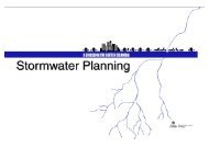
<strong>Stormwater</strong> <strong>Source</strong> <strong>Control</strong> <strong>Design</strong> <strong>Guidelines</strong> <strong>2005</strong>Absorbent LandscapeAbsorbent LandscapeApplicationMost landscape – either natural or manmade – acts like asponge to soak up, store and slowly release rainfall. In mostGVRD natural wooded conditions without paving and roofdevelopment, 90% of rainfall volume that lands on naturalwatersheds never becomes runoff, but is either soaked into thesoils or evaporates (Stephens et al., 2002). The trees, shrubs,grasses, surface organic matter, and soils all play a role in thisabsorbent landscape.<strong>Stormwater</strong> Variables of Absorbent LandscapeFigure 1-1: <strong>Stormwater</strong> variables of absorbent landscape.Figure 1-1 shows a schematic representation of the 12stormwater variables of absorbent landscape discussed below.Keeping these variables in balance is the key to successfulstormwater source control using absorbent landscape.Greater Vancouver Sewarage & Drainage District25
Absorbent Landscape <strong>Stormwater</strong> <strong>Source</strong> <strong>Control</strong> <strong>Design</strong> <strong>Guidelines</strong> <strong>2005</strong>Winter Tree Canopies Intercept 15%-27% of Rainfall1. Crown InterceptionFigure 1-2: Interception, stemflow and throughfall data from California(Xiao et al., 2000)Scientific studies have shown that asignificant amount of grossprecipitation is intercepted (i.e., neverreaches the ground) by tree crowns. A50 year old evergreen forest inScotland had canopy interception of28% of annual rainfall (Johnston,1990). Studies of open grown urbantrees in Davis, California (averageannual rainfall of 446 mm) haveshown significant crown interceptioneven in winter - about 15% by aleafless pear tree, and about 27% by abroadleaf evergreen oak (Figure 1-2 -Xiao et al., 2000).2. Throughfall and StemflowPlants provide a stormwater detention function, slowing downrain before it hits the ground surface. Although some rain fallsthrough the canopy as free throughfall, a significant portionlands on either leaf or twigs, where it is delayed prior tocreating canopy drip. Some of this rainfall flows down twigsand branches to become stemflow at the tree trunk. The twigs,branches and rough bark of leafless deciduous trees play asignificant role in stormwater detention.3. EvapotranspirationTrees, shrubs, grasses and other plants draw water up from thesoil to the leaves, where the stomata (openings) in the leavesallow for evapo-transpiration. Evaporation also occurs fromsurface water (puddles, lakes, streams, rooftops) and fromsurface soils, snow and tree/plant surfaces. The combinationof tree canopy interception and evapotranspiration in a naturalrainforest can approach 40% of annual rainfall (Stephens etal., 2002).Rainfall Storage in Soil is 7% to 18% of Soil Volume4. Soil Water StorageSoils are the most significant landscape storage mechanism forstormwater. Landscape soils typically store from 7% (sand) to18% (loam) of their volume as water before becomingsaturated to field capacity and generating flow-through orrunoff. Loamy soils store more water than sandy soils(Ferguson, 1994).26Greater Vancouver Sewerage & Drainage District
<strong>Stormwater</strong> <strong>Source</strong> <strong>Control</strong> <strong>Design</strong> <strong>Guidelines</strong> <strong>2005</strong>Absorbent Landscape5. Soil InfiltrationThe rate at which water soaks into soils (the infiltration rate orsaturated hydraulic conductivity) varies depending on thetexture and amount of organic matter in the soil. Fine texturedsoils with silt and clay exceeding 35% by volume tend to havelow infiltration rates (0.6 to 6 mm/hr),whereas sand surface soils are very opento infiltration (210 mm/hr), with loam soilshaving moderate infiltration rates (13mm/hr).Surface crusting and compaction of the top2 mm of soil can be an importantlimitation. Thin crusts can be formed onall bare soil surfaces , including fine sand,due to raindrop impact. Surface crustingrisks can be addressed by avoiding erosionand sedimentation that carries fines ontothe soil surface, and by providing surfacemulching, vegetation, organic matter andrelated soil life in the surface soil (Figure 1-3 - Ferguson, 1994).Organic Matter Maintains Soil Infiltration Rates6. Surface VegetationPlant materials work to condition the soil – providing a regularsupply of organic matter through leaf drop, and opening upmacropores in the soil through the process of root growth,death and decay. Soils with vegetated surfaces have highermaintained surface infiltration rates than bare soils, becausemacroporosity of the soil is continually regenerated by plantsand animals (Ferguson, 1994). Surface vegetation is also veryeffective at stopping erosion from starting. Leaves of grassesand similar plants on the soil surface also act as physical filtersto runoff – causing sediments and attached pollutants likemetals and phosphorus to drop out of the water.7. Organics and CompostAddition of organic matter or compost to soils increases theinfiltration and moisture holding capability of sandy, silt/clay ortill soils that are not permanently saturated. Organic matter inthe soil reduces the need for fertilization and can reduce theneed for supplementary watering by 60% when compared tosites with unamended topsoil (Chollak and Rosenfeld, 1999).For stormwater purposes, organic matter targets of 8% forlawn areas and 15% for shrub areas are recommended.Compost blankets and berms for erosion control have beentested and proven to be as effective as silt fence (Tyler, 2002).Figure 1-3: Infiltration rate of a sandy loam under continous watersprinkling at a rate in excess of intake with a series of 4 surfaceconditions (Ferguson, 1994: 191)Greater Vancouver Sewarage & Drainage District27
Absorbent Landscape <strong>Stormwater</strong> <strong>Source</strong> <strong>Control</strong> <strong>Design</strong> <strong>Guidelines</strong> <strong>2005</strong>8. Soil LifeCompost and soil is a living material – a mature topsoil with5% organic matter can contain as much as 7.5 tons oforganisms per hectare (Carpenter-Biggs, 2002). Together withplant roots, soil fauna such as earthworms, insects, ants, andmoles form and maintain macropores in the soil. These largerorganisms rely on a soil ecosystem of microscopic speciessustained by organic matter. In soils or surface crusts of lowconductivity, even a small amount of macroporosity canincrease hydraulic conductivity by more than 10 times(Ferguson, 1994).9. InterflowSummer base flow in streams is maintained by ‘interflow’ ofrainfall in shallow soils. With a typical water flow rate of12.5mm/hr in loam, a raindrop would travel through the soilat 300mm/day, taking 100 days to travel 30 metres.10. Deep GroundwaterSoil water also flows by gravity through soils or fractured rockto deep groundwater, which stores 98.4% of the unfrozen freshwater of the earth, as compared to 1.4% in lakes and streams(Montgomery, 1987). Protection of the quality of thisgroundwater through the filtration processes in surface soils iscritical to drinking water supplies.11. Water Quality ImprovementInfiltration of stormwater through healthy soil is one of themost effective practices to improve water quality and removeurban pollutants.Impermeable Surfaces Create 8-10 times the Runoffof Absorbent Landscape12. Impermeable Surfaces and Surface RunoffImpermeable pavement and rooftop removes the functions ofabsorbent landscape. Volume of runoff from impermeableroof and pavement without any best management practices is8-10 times the runoff from absorbent landscape. Thisincreased runoff dramatically increases flows in streams,exceeding the mean annual flood level more often, whichresults in stream erosion, flooding and loss of property andhabitat (Stephens et al., 2002).28Greater Vancouver Sewerage & Drainage District
<strong>Stormwater</strong> <strong>Source</strong> <strong>Control</strong> <strong>Design</strong> <strong>Guidelines</strong> <strong>2005</strong>Absorbent LandscapeTypical Infiltration Rates of SoilsSoil is comprised of sand, silt, clay and organic matter invarying proportions that affect the infiltration rate. For designpurposes, infiltration rates should be measured at the locationand depth of the proposed infiltration using a percolation testor a double-ring infiltrometer.Typical published infiltration rates shown in Table 1-1 areSaturated Hydraulic Conductivity (Ferguson, 1994).Even minor infiltration rates are significant when applied overtime – a 1mm/hour infiltration rate absorbs 24mm per day, or168mm per week.Table 1-1: Typical Infiltration RatesUSDA Soil ClassSaturated hydraulicconductivity (mm/hr)Sand 210Loamy sand 61*Sandy loam 26*Loam 13Silt loam 6.8Sandy clay loam 4.3Clay loam 2.3Silty clay loam 1.5Sandy clay 1.2Silty clay 0.9Clay 0.6*Target soil texture for growing medium Level 2 “Groomed”and Level 3 “Moderate” landscape areas in B.C. LandscapeStandard, which represent a good balance between infiltrationperformance and water retention capabilities.Greater Vancouver Sewarage & Drainage District29
Absorbent Landscape <strong>Stormwater</strong> <strong>Source</strong> <strong>Control</strong> <strong>Design</strong> <strong>Guidelines</strong> <strong>2005</strong>LimitationsAbsorbent landscape needs to be implemented properly toavoid conditions that would cause reduced infiltration atthe surface due to sedimentation, excessive compaction, orlack of vegetative cover. Quality control is necessaryregarding installed soil properties, erosion and sedimentcontrol, and establishment of vegetation.Site plans that drain large areas of impervious area intosmall areas of landscape risk overwhelming the absorbentcapabilities of soil. All designs should calculate theprojected flows and water balance, and should provide foran overflow – surface or piped – to the major storm floodcontrol system.To meet typical performance targets (e.g., infiltrating thefirst 25 – 60mm of rainfall), the amount of absorbentlandscape area on a site or in a drainage basin must bebalanced with the amount of impervious area. This willimpact many aspects of urban design - e.g., by promotingbuilding forms that minimize impervious buildingfootprints, by placing landscape over parking or rooftops,or by designing narrower roads and larger landscapeislands in parking areas.30Greater Vancouver Sewerage & Drainage District
<strong>Stormwater</strong> <strong>Source</strong> <strong>Control</strong> <strong>Design</strong> <strong>Guidelines</strong> <strong>2005</strong>Absorbent Landscape<strong>Design</strong> <strong>Guidelines</strong>Photo Credit: Lanarc Consultants Ltd.1. Maximize the area of absorbent landscape – eitherexisting or constructed – on the site.2. Conserve as much natural forest land, existingtrees and undisturbed soil as is compatible with theproject. Provide temporary fencing of theseprotected areas during construction.3. Minimize impervious area through such techniquesas multi-storey buildings, narrower roads,minimum parking, larger landscape areas, greenroof, and pervious paving.4. Disconnect impervious areas from the storm sewersystem, having them drain to absorbent landscapewith only an overflow to the storm drainagesystem.Drainage from parking area to landscape.5. <strong>Design</strong> absorbent landscape areas as gentlysloping (2%) or dished (concave) areas thattemporarily store stormwater and allow it to soak in(maximum ponding time of 2 days), with overflow onlyoccurring in large rain events.6. When planting, maximize the vegetation canopy coverover the site. Cover by multi-layered evergreen trees andshrubs is ideal, but deciduous tree cover also is beneficialfor stormwater management.7. Use native planting species where feasible. Non-nativeplantings with similar attributes to native may be suitable inconditions where natives would grow too large or not meetother urban design objectives.8. Ensure adequate growing medium depth for bothhorticultural and stormwater needs – generally a minimumof 150mm depth for lawn areas, and 450mm depth forshrub/tree areas. In wetter areas of the GVRD near themountains with till subsoils, a minimum growing mediumdepth of 300mm for lawn areas is required to store 60mmof rainfall.9. Test growing medium for physical and chemical properties,and amend it to provide approximately 8% organic matterfor lawns, and 15% organic matter for planting beds, inthe upper 200mm of growing medium.10. Do not over-compact landscape subgrade or growingmedium. Optimum compaction is firm against deepfootprints (about 80% Proctor Density). Excessivecompaction reduces infiltration rates. Rip or till subsoilsthat are excessively compacted. Aerate compacted surfacesoils.Greater Vancouver Sewarage & Drainage District31
Absorbent Landscape <strong>Stormwater</strong> <strong>Source</strong> <strong>Control</strong> <strong>Design</strong> <strong>Guidelines</strong> <strong>2005</strong>11. Scarify subgrade surfaces prior to placing growingmedium, and rototill through layers of growing medium tocreate a transition in soil texture rather than discrete soillayers. Do not install soils in layers of different textures, asthis can create barriers to infiltration.12. Provide vegetative cover (grass, groundcovers, shrubs,trees) or organic cover (mulch, straw, wood fibre) toabsorbent landscape as early as possible in theconstruction process, and prior to winter storms, to avoidsurface crusting from raindrop impact and to maintainsurface permeability.13. Provide effective erosion control during construction,including erosion control on upstream sites that may flowinto the absorbent landscape. Delay installation ofconstructed absorbent landscape until sources of potentialerosion in the upstream drainage area have beenpermanently stabilized.Photo Credit: Lanarc Consultants Ltd.Guideline SpecificationsMaterials and methods shall meet Master MunicipalConstruction Document 2000 requirements, including theSection 02921 requirements for Growing Medium, withorganic matter requirements amended as follows:For lawn areas minimum 8%For planting areas minimum 15%Straw laid on surface to preventerosion and crusting from raindropimpact.32Greater Vancouver Sewerage & Drainage District
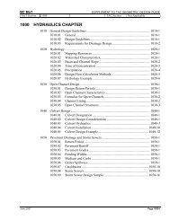
<strong>Stormwater</strong> <strong>Source</strong> <strong>Control</strong> <strong>Design</strong> <strong>Guidelines</strong> <strong>2005</strong>Infiltration SwaleInfiltration Swale SystemDescriptionThe Infiltration Swale System combines aspects of grass swalesand infiltration trenches.The surface component of an infiltration swale is a shallowgrassed channel, accepting flows from small areas of adjacentpaved surfaces such as roads and parking. The swale isdesigned to hold the water quality storm behind a weir, andthen allow it to infiltrate slowly through a soil bed to anunderlying drain rock reservoir system.The surface soils and drain rock reservoir are sized to store thedesign storm event, and to allow it to infiltrate slowly intounderlying soils. A perforated drain placed near the top of thedrain rock reservoir provides an underground overflow, whichalso maintains drainage of adjacent road base courses. Thesurface swale and weir structures provide conveyance forlarger storm events to a surface outlet.Other common terms used are Dry Swale with Underdrain(Stephens et al., 2002) or Swale/Trench Element (MUNLV-NRW, 2001).Photo Credit: Lanarc ConsultantsDrop curb at pavement edge to grassinfiltration swale.Application <strong>Design</strong>ed to treat the water quality volume and conveylarger flows (Stephens et al., 2002). Provision of underground overflow allows use of thetechnique in most soils, including clay with infiltration ratesas low as 0.6mm/hr. Suitable for most development situations – residentialareas, municipal office complexes, rooftop runoff, parkingand roadway runoff, parks and greenspace, golf courses(Stephens et al., 2002). With proper weir spacing, practical for profiles up to 10%slope.Limitations Maximum contributing area 2 ha (Stephens et al., 2002). Minimum depth from base of drain rock reservoir to watertable 610 mm (Stephens et al., 2002). Identify pollutant sources, particularly inindustrial/commercial hotspots, that require pre-treatmentor source control upstream of this BMP. (Maryland Dept.Environmental Resources Program, 2000).Greater Vancouver Sewerage & Drainage District33
Infiltration Swale <strong>Stormwater</strong> <strong>Source</strong> <strong>Control</strong> <strong>Design</strong> <strong>Guidelines</strong> <strong>2005</strong><strong>Design</strong> should provide for drain rock reservoir to drain in96 hours to allow aerobic conditions for water qualitytreatment.<strong>Design</strong> <strong>Guidelines</strong>Photo Credit: Lanarc ConsultantsFlush curb (left) to grass filter tovegetated (shrubs, groundcover)swale.1. The swale infiltration area should be approximately 10-20% of the upstream impervious area that it serves, with itssizing preferably calculated by continuous flow modelling.2. Flow to the swale should be distributed sheet flow,travelling through a grassy filter area at the swale verges(500 mm min., >3000 mm desirable). Provide pretreatmenterosion control to avoid sedimentation in theswale. Provide non-erodable material, sediment cleanoutbasins, and weir flow spreaders at point-source inlets(Maryland Dept. Environmental Resource Programs,2001).3. Provide vegetated erosion control along all sides of weirand at drainage inlets.4. Pavement edge at the swale may be wheel stop, flushcurb, or reverse curb (Figure 2E). Provide a 25mm dropat the edge of paving to the swale soil surface, to allow forpositive drainage and buildup of road sanding/organicmaterials at this edge.5. Swale planting is typically sodded lawn. Low volumeswales can be finished with a combination of grasses,shrub, groundcover and tree planting to provide a 100%vegetated cover within 2 years of planting.6. Swale longitudinal slope should be 1-2%, or dishedbetween weirs.7. Swale bottom width - 600mm minimum, 2400mmmaximum, flat in cross section.8. Swale surface side slopes - 3(horizontal):1(vertical)maximum, 4:1 preferred for maintenance.9. Weirs to have level top to spread flows and avoidchannelization, keyed in 100mm minimum. Integratedmowing strip is desirable in lawn areas.10. <strong>Design</strong> stormwater conveyance using Manning’s formula,with attention to erosion and channel stability duringmaximum flows.11. Maximum ponded level: 150mm (Maryland Dept.Environmental Resource Programs, 2001).12. Drawdown time for the maximum surface ponded volume– 48 hours maximum ( 24 hours maximum - MarylandDept. Environmental Resource Programs, 2001).34Greater Vancouver Sewerage & Drainage District
<strong>Stormwater</strong> <strong>Source</strong> <strong>Control</strong> <strong>Design</strong> <strong>Guidelines</strong> <strong>2005</strong>Infiltration Swale13. Minimum freeboard to adjacent paving: 100mm or inaccordance with swale conveyance design.14. Treatment soil depth: 450mm is desirable, minimum150mm if design professional calculates adequatepollutant removal (Maryland Dept. EnvironmentalResource Programs, 2001), or 100 min. growing mediumover 100mm min washed sand (MUNLV-NRW, 2001).15. Drain rock reservoir bottom shall be level.16. Underground weirs (Figure 2A) of undisturbed nativematerial or constructed ditch blocks shall be provided tocreate underground pooling in the reservoir sufficient forinfiltration performance.17. A non-erodible outlet or spillway must be established todischarge overflow (Maryland Dept. EnvironmentalResource Programs, 2001).18. Avoid utility or other crossings of the swale. Where utilitytrenches must be constructed crossing below the swale,install trench dams to avoid infiltration water following theutility trench.<strong>Design</strong> OptionsDrain rock reservoir and underdrain may be deleted whereinfiltration tests by the design professional taken at the level ofthe base of the proposed construction show an infiltration ratethat exceeds the maximum inflow rate for the design storm.The attached Drawings 2B through 2D, and the InfiltrationSwale System Summary Poster illustrate the options.Photo Credit: Water Concept KronsbergPhoto Credit: Water Concept KronsbergSwale with check dams underconstruction.Swale with check dams in operation.Greater Vancouver Sewerage & Drainage District35
Infiltration Swale <strong>Stormwater</strong> <strong>Source</strong> <strong>Control</strong> <strong>Design</strong> <strong>Guidelines</strong> <strong>2005</strong>Guideline SpecificationsPhoto Credit: Lanarc ConsultantsInfiltration swale in parking area –Water Pollution <strong>Control</strong> Laboratory,Portland, Oregon.Materials shall meet Master Municipal Construction Document2000 requirements, and:1. Infiltration Drain Rock: clean round stone or crushed rock,75mm max, 38mm min, 40% porosity (Maryland Dept.Environmental Resource Programs, 2001).2. Pipe: PVC, DR 35, 150 mm min. dia. with cleanouts.3. Geosynthetics: as per Section 02498, select for filtercriteria or from approved local government product lists.4. Sand: Pit Run Sand as per Section 02226.5. Growing Medium: As per Section 02921 Topsoil andFinish Grading, Table 2, including the requirement forminimum saturated hydraulic conductivity of 2 cm/hr., withorganic matter requirements amended as follows:a. For lawn areas minimum 8%b. For planting areas minimum 15%6. Seeding: to Section 02933 Seeding or 02934 HydraulicSeeding (note – sodding will be required for erosioncontrol in most swales, subject to the erosion controlprofessional’s decision).7. Sodding: to Section 02938 Sodding.Construction practices shall meet Master MunicipalConstruction Document 2000 requirements, and:1. Isolate the swale site from sedimentation duringconstruction, either by use of effective erosion andsediment control measures upstream, or by delaying theexcavation of 300mm of material over the final subgradeof the swale until after all sediment-producing constructionin the drainage area has been completed (Maryland Dept.Environmental Resource Programs, 2001).2. Prevent natural or fill soils from intermixing with theInfiltration Drain Rock. All contaminated stone aggregatemust be removed and replaced (Maryland Dept.Environmental Resource Programs, 2001).3. Infiltration Drain Rock shall be installed in 300mm lifts andcompacted to eliminate voids between the geotextile andsurrounding soils (Maryland Dept. Environmental ResourcePrograms, 2001).4. Maintain grass areas to mowed height between 50mmand 150mm., but not below the design water level.Landscape Maintenance standards shall be to the BCLandscape Standard, 6th Edition, Maintenance Level 4:Open Space / Play Area.36Greater Vancouver Sewerage & Drainage District
12OUTLET TO PIPE SYSTEM OR WATERCOURSEWEIR KEYED INTO SWALE SIDE SLOPE34GROWING MEDIUMSAND56UNDERGROUND WEIR OF COMPACTED NATIVEMATERIAL OR EQUIVALENT TO CREATESUBSURFACE BASINEXISTING SCARIFIED SUB-SOIL789DRAIN ROCK RESERVOIR (OPTIONAL)PERFORATED DRAIN PIPE (OPTIONAL)HIGH FLOW OVERFLOW87 6 54 3 2 9 12% SLOPE10m MAX2.0% SLOPE 2.0% SLOPELEVEL BASE (TYP)10m MAX5% SLOPE 10% SLOPE2.0% SLOPE2.0%2.0%2.0%2.0%2.0%5m MAX2AINFILTRATION SWALENot To ScaleLongitudinal Profile37
FLOWGROWING MEDIUMADJACENT GRADE200200SAND LAYERGROWING MEDIUM6SAND LAYERLEVELDETAIL SECTION - WEIR WITH PONDING13:1 MAXSLOPEFLOW3:1 MAXSLOPEGROWING MEDIUMADJACENT GRADE200200SAND LAYERGROWING MEDIUM2000 MIN - 4200 MAXPLANDETAIL SECTION - WEIR WITHOUT PONDING2400 MIN - 4200 MAX12343:1 MAXLEVEL600 MIN -2400 MAX1234WEIR KEYED INTO SWALE SIDESLOPEGROWING MEDIUMSANDEXISTING SCARIFIED SUBSOIL56TRENCH DAMS AT ALL UTILITYCROSSINGPROVIDE EROSION CONTROLALONG ALL SIDES OF WEIR ANDAT DRAINAGE INLETSSECTION52BFULL INFILTRATION SWALENot To ScalePlan / Section38
FLOWGROWING MEDIUMADJACENT GRADE200200SAND LAYERGROWING MEDIUM8SAND LAYERLEVELDETAIL SECTION - WEIR WITH PONDING13:1 MAXSLOPEFLOW3:1 MAXSLOPEGROWING MEDIUMADJACENT GRADE200200SAND LAYERGROWING MEDIUM2000 MIN - 4200 MAXPLANDETAIL SECTION - WEIR WITHOUT PONDING23:1 MAX2400 MIN - 4200 MAXLEVEL112WEIR KEYED INTO SWALE SIDESLOPEGROWING MEDIUM3456600 MIN -2400 MAX34567SANDEXISTING SCARIFIED SUBSOILDRAIN ROCK RESERVOIRGEOTEXTILE FILTER ALONG ALLSIDES OF RESERVOIRTRENCH DAMS AT ALL UTILITYCROSSINGSSECTION78PROVIDE EROSION CONTROLALONG ALL SIDES OF WEIR ANDAT DRAINAGE INLETS2CFULL INFILTRATION SWALE WITH RESERVOIRNot To ScalePlan / Section39
FLOWADJACENT GRADE200GROWING MEDIUM200SAND LAYERGROWING MEDIUM9SAND LAYERLEVELDETAIL SECTION - WEIR WITH PONDING13:1 MAXSLOPEFLOW3:1 MAXSLOPEGROWING MEDIUMADJACENT GRADE200200SAND LAYERGROWING MEDIUM2000 MIN - 4200 MAXPLANDETAIL SECTION - WEIR WITHOUT PONDING2400 MIN - 4200 MAX11WEIR KEYED INTO SWALE SIDESLOPE2LEVEL2GROWING MEDIUM3:1 MAX3SAND3545EXISTING SCARIFIED SUBSOILPERFORATED UNDERDRAIN(150mm DIA MIN.)674300 MIN600 MIN -2400 MAX678DRAIN ROCK RESERVOIRGEOTEXTILE FILTER ALONG ALLSIDES OF RESERVOIRTRENCH DAMS AT ALL UTILITYCROSSINGSECTION89PROVIDE EROSION CONTROLALONG ALL SIDES OF WEIR ANDAT DRAINAGE INLETS2DPARTIAL INFILTRATION SWALE WITH RESERVOIR AND SUBDRAINNot To ScalePlan / Section40
1125mm VERTICALDROP (TYP)24:1 MAX. SLOPE FORFIRST 500mm3REINFORCED WITHEROSION CONTROLTREATMENT ANDFLOW SPREADERAT POINTS OFWATER ENTRY(TYP.)WHEEL STOP WITH GAPS2FLUSH CURB3REVERSE CURB2ECURBING OPTIONSNot To ScaleSection41
Infiltration Swale <strong>Stormwater</strong> <strong>Source</strong> <strong>Control</strong> <strong>Design</strong> <strong>Guidelines</strong> <strong>2005</strong>This page is intentionally left blank.42Greater Vancouver Sewerage & Drainage District
<strong>Stormwater</strong> <strong>Source</strong> <strong>Control</strong> <strong>Design</strong> <strong>Guidelines</strong> <strong>2005</strong>Infiltration Rain GardenInfiltration Rain GardenPhoto Credit: Lanarc Consultants Ltd.DescriptionThe Infiltration Rain Garden is a form of bioretentionfacility, designed to have the aesthetic appeal of agarden, as opposed to a purely functional appearance.Rain Gardens are commonly a concave landscape areawhere treated runoff from roofs or paving is allowed topond temporarily while infiltrating into deep constructedsoils below (See Drawing 3A).The surface planting of Rain Gardens is dominated bytrees, shrubs, and groundcovers, with planting designsrespecting the various soil moisture conditions in thegarden. Plantings may also include rushes, sedges andother grass-like plants, as well as sodded lawn areas forerosion control and multiple uses.On subsoils with low infiltration rates, Rain Gardensoften have a drain rock reservoir and perforated drainsystem to collect excess water. (See Drawing 3B &3C).The perforated drain system may connect to a controlstructure in a catch basin that provides overflow whilemaintaining a slow decanting of the water in the raingarden between storms (See Drawing 3D).While usually designed as a ‘standalone’ facility withoutconveyance, new designs are evolving that put a seriesof Rain Gardens along linear areas like roads – withweirs and surface conveyance similar to InfiltrationSwales.Other common terms used are Bioretention and DrySwale with Underdrain (Stephens et al., 2002) or Swale /Trench Element (MUNLV-NRW, 2001).Formal rain garden, Buckman Terrace, PortlandOregon.Photo Credit: Lanarc Consultants Ltd.Informal rain garden, Water Pollution <strong>Control</strong>Laboratory, Portland OregonPhoto Credit: Lanarc Consultants Ltd.Application and LimitationsApplication and Limitations are similar to InfiltrationSwales.Rain garden overflow, Buckman Terrace, PortlandOregon.Greater Vancouver Sewerage & Drainage District43
Infiltration Rain Garden <strong>Stormwater</strong> <strong>Source</strong> <strong>Control</strong> <strong>Design</strong> <strong>Guidelines</strong> <strong>2005</strong><strong>Design</strong> <strong>Guidelines</strong>1. The Rain Garden area should be 10-20% of the upstreamimpervious area that it serves, preferably sized bycontinuous flow modelling. Common rain garden size isabout 50 m 2 draining 250m 2 of impervious area, althoughthis sizing and proportion will vary by rainfall and soilcharacteristics. Smaller, distributed Rain Gardens arebetter than single large scale facilities.2. Site Rain Gardens similar to other infiltration facilities –minimum 30m from wells, minimum 3 m downslope ofbuilding foundations, and only in areas where foundationshave footing drains.3. Provide pretreatment erosion control to avoidsedimentation in the garden. Provide non-erodablematerial, sediment cleanout basins, and weir flowspreaders at point-source inlets. Flow to the swale shouldbe distributed sheet flow, travelling through a grassy filterarea or grass swale prior to entering the Rain Garden(500 mm minimum, greater than 3000 mm desirablegrassy pretreatment swale length; Claytor and Schueler,1996).4. Rain Garden bottom (Drawing 3A): flat cross section, witha longitudinal slope of 2% (or 1% by US001, or dished byGE004). Provide a 50mm – 75mm layer of organic mulch– well aged compost, bark mulch or similar weed freematerial. The mulch is important for both erosion controland maintaining infiltration capacity.5. Rain Garden bottom width: 600mm minimum, 3000mmdesirable, length:width ratio of 2:1 (Gibb et al., 1999).6. Rain Garden side slopes 2 horizontal : 1 verticalmaximum, 4:1 preferred for maintenance. Provide organicmulch on side slopes similar to bottom.7. Maximum ponded level: 150mm (Gibb et al., 1999),300mm (NRW).8. Drawdown time for the maximum surface ponded volume:48 hours (72 hours max. - Maryland Dept. EnvironmentalResource Programs, 2001).9. Treatment soil depth: 450mm minimum (City of Portland,2002), 1200mm desirable (Gibb et al., 1999). Treatmentsoil should have a minimum infiltration rate of 13mm/hr,with 6mm/hr used for design.10. Slope of the drain rock reservoir bottom shall be level.11. A non-erodible outlet or spillway must be established todischarge overflow (Maryland Dept. EnvironmentalResource Programs, 2001).44Greater Vancouver Sewerage & Drainage District
<strong>Stormwater</strong> <strong>Source</strong> <strong>Control</strong> <strong>Design</strong> <strong>Guidelines</strong> <strong>2005</strong>Infiltration Rain Garden12. Avoid utility or other crossings of the Rain Garden. Whereutility trenches must be constructed crossing below thegarden, install trench dams to avoid infiltration waterfollowing the utility trench.13. Rain gardens can be constructed in a variety of shapes,including formal rectalinear flow-through planters(Drawing 3E). Get geotechnical advice prior to siting raingardens closer than 3m to building foundations.<strong>Design</strong> Options:Infiltration Rain Gardens may take a variety of shapes, frominformal, organically shaped ‘bowls’ to formal, rectilinearplanting areas and planters.Drain rock reservoir and underdrain may be deleted whereinfiltration tests by the design professional taken at the level ofthe base of the proposed construction show an infiltration ratethat exceeds the inflow rate for the design storm.Photo Credit: Lanarc Consultants Ltd.Flow-thru planter – a formal-shaped rain gardenthat provides water quality treatment and limitedflow attenuation – adapted to a near-buildinglocation at Buckman Terrace in Portland, Oregon.Greater Vancouver Sewerage & Drainage District45
Infiltration Rain Garden <strong>Stormwater</strong> <strong>Source</strong> <strong>Control</strong> <strong>Design</strong> <strong>Guidelines</strong> <strong>2005</strong>Guideline SpecificationsMaterials shall meet Master Municipal Construction Document2000 requirements, and:1. Infiltration Drain Rock: clean round stone or crushed rock,75mm max, 38mm min, 40% porosity (Maryland Dept.Environmental Resource Programs, 2001).2. Pipe: PVC, DR 35, 150 mm min. dia., with cleanouts.3. Geosynthetics: as per Section 02498, select for filtercriteria or from approved local government product lists.4. Sand: Pit Run Sand as per Section 02226.5. Growing Medium: As per Section 02921 Topsoil andFinish Grading, Table 2, including the requirement forminimum saturated hydraulic conductivity of 2 cm/hr., withorganic matter requirements amended as follows:a. For lawn areas minimum 8%b. For planting areas minimum 15%6. Seeding: to Section 02933 Seeding or 02934 HydraulicSeeding (note – sodding will be required for erosioncontrol in most instances).7. Sodding: to Section 02938 Sodding.Construction Practices shall meet Master MunicipalConstruction Document 2000 requirements, and:1. Isolate the swale site from sedimentation duringconstruction, either by use of effective erosion andsediment control measures upstream, or by delaying theexcavation of 300mm of material over the final subgradeof the swale until after all sediment-producing constructionin the drainage area has been completed (Maryland Dept.Environmental Resource Programs, 2001).2. Prevent natural or fill soils from intermixing with theInfiltration Drain Rock. All contaminated stone aggregatemust be removed and replaced (Maryland Dept.Environmental Resource Programs, 2001).3. Infiltration Drain Rock shall be installed in 300mm lifts andcompacted to eliminate voids between the geotextile andsurrounding soils (Maryland Dept. Environmental ResourcePrograms, 2001).4. Maintain grass areas to mowed height between 50mmand 150mm., but not below the design water quality flowlevel. Landscape Maintenance standards shall be to theBC Landscape Standard, 6th Edition, Maintenance Level4: Open Space / Play.46Greater Vancouver Sewerage & Drainage District
12345678TREE, SHRUB ANDGROUNDCOVERPLANTINGSGROWING MEDIUMMIN. 450mm DEPTHORGANIC MULCHFLAT SUBSOIL - SCARIFIEDOVERFLOW (STANDPIPEOR SWALE)SECONDARY OVERFLOWINLET AT CATCH BASINOUTFLOW PIPE TO STORMDRAIN OR SWALE SYSTEMTRENCH DAMS AT ALLUTILITY CROSSINGS1326 82:1 MAX2:1 MAX4504753ARAIN GARDEN - FULL INFILTRATIONNot To ScaleSection47
12345678910TREE, SHRUB ANDGROUNDCOVERPLANTINGSGROWING MEDIUMMIN. 450mm DEPTHORGANIC MULCHDRAIN ROCK RESERVOIRFLAT SUBSOIL - SCARIFIEDGEOTEXTILE ALONG ALLSIDES OF DRAIN ROCKRESERVOIROVERFLOW (STANDPIPEOR SWALE)SECONDARY OVERFLOWINLET AT CATCH BASINOUTFLOW PIPE TO STORMDRAIN OR SWALE SYSTEMTRENCH DAMS AT ALLUTILITY CROSSINGS1328 102:1 MAX2:1 MAX4504596 73BRAIN GARDEN - FULL INFILTRATION WITH RESERVOIRNot To ScaleSection48
1234567891011TREE, SHRUB ANDGROUNDCOVERPLANTINGSGROWING MEDIUMMIN. 450mm DEPTHORGANIC MULCHDRAIN ROCK RESERVOIRFLAT SUBSOIL - SCARIFIEDPERFORATED DRAIN PIPE(150mm DIA MIN.)GEOTEXTILE ALONG ALLSIDES OF DRAIN ROCKRESERVOIROVERFLOW (STANDPIPEOR SWALE)SECONDARY OVERFLOWINLET AT CATCH BASINOUTFLOW PIPE TO STORMDRAIN OR SWALE SYSTEMTRENCH DAMS AT ALLUTILITY CROSSINGS1329 112:1 MAX2:1 MAX45045106 7 83CRAIN GARDEN - PARTIAL INFILTRATIONNot To ScaleSection49
1123456789101112TREE, SHRUB ANDGROUNDCOVERPLANTINGSGROWING MEDIUMMIN. 450mm DEPTHORGANIC MULCHDRAIN ROCK RESERVOIRFLAT SUBSOIL - SCARIFIEDPERFORATED DRAIN PIPE(150mm DIA MIN.)GEOTEXTILE ALONG ALLSIDES OF DRAIN ROCKRESERVOIROVERFLOW (STANDPIPEOR SWALE)FLOW RESTRICTORASSEMBLYSECONDARY OVERFLOWINLET AT CATCH BASINOUTFLOW PIPE TO STORMDRAIN OR SWALE SYSTEMTRENCH DAMS AT ALLUTILITY CROSSINGS3210 122:1 MAX2:1 MAX5004300 MIN95116 7 83DRAIN GARDEN - PARTIAL INFILTRATION WITH FLOW RESTRICTORNot To ScaleSection50
1RAIN WATER LEADER OROTHER INLET4DAMP PROOFING ORWATERPROOFING MEMBRANE9GEOTEXTILE ALONG ALLSIDES OF RESERVOIR123SPLASH BLOCK ANDSURFACE STONETREATMENTIMPERVIOUS WATERBARRIER (eg. HIGH IMPACTPOLYSTYRENE)5678DRAIN ROCK OR PVC SHEETDRAINFOOTING DRAINGROWING MEDIUMCOMPACTED SUBGRADE10111213DRAIN ROCK RESERVOIRPERFORATED DRAIN PIPE TOOUTLET(150Ø MINIMUM)SURFACE OVERFLOW NOTCHOR OVERFLOW STAND PIPEPLANTER WALL135021232% MIN. AWAY FROM FOUNDATION7445053m MIN. OR AS RECOMMENDEDBY GEOTECHNICAL REPORT300 MIN2% MIN3EFLOW THROUGH PLANTERNot To Scale6 89 10 11Section51
1RAIN WATER LEADER OROTHER INLET4DAMP PROOFING ORWATERPROOFING MEMBRANE9GEOTEXTILE ALONG ALLSIDES OF RESERVOIR123SPLASH BLOCK ANDSURFACE STONETREATMENTIMPERVIOUS WATERBARRIER (eg. HIGH IMPACTPOLYSTYRENE)5678DRAIN ROCK OR PVC SHEETDRAINFOOTING DRAINGROWING MEDIUMCOMPACTED SUBGRADE10111213DRAIN ROCK RESERVOIRPERFORATED DRAIN PIPE TOOUTLET(150Ø MINIMUM)SURFACE OVERFLOW NOTCHOR OVERFLOW STAND PIPEPLANTER WALL135021232% MIN. AWAY FROM FOUNDATION7445053m MIN. OR AS RECOMMENDEDBY GEOTECHNICAL REPORT300 MIN2% MIN3FINFILTRATION PLANTERNot To Scale6 89 10 11Section52
<strong>Stormwater</strong> <strong>Source</strong> <strong>Control</strong> <strong>Design</strong> <strong>Guidelines</strong> <strong>2005</strong>Pervious PavingPervious PavingDescriptionPervious paving is a surface layer of paving systems whichallows rainfall to percolate into an underlying reservoir base,where rainfall is stored and either exfiltrated to underlyingsubgrade, or removed by a subdrain.The surface component of pervious paving can be:- Porous asphalt or porous concrete, where fines are notincluded in the mix, providing a high void ratio thatallows water to pass through. There have beenproblems with surface clogging of this type of pavement.- Concrete or plastic grid pavers, where a structural loadbearing matrix has large voids that are filled with apermeable material – usually gravel or soil - and whichoften have grass in these voids.- Permeable unit pavers, made up of impervious concretemodular pavers with gapped joints that allow water topercolate between the pavers.The focus of this section is on the permeable unit pavers, asthey have been used with consistent success and appearmore resilient to clogging than porous paving alternatives.(James et al., 2003)Photo Credit: Lanarc Consultants Ltd.Plastic grid pavers in parking, White RockOperations Centre.Photo Credit: Lanarc Consultants Ltd.ApplicationSuitable for low traffic areas – e.g., driveways, parkingareas, storage yards, bike paths, walkways, recreationalvehicle pads, service roads, fire lanes (GVSDD, 1999).Can receive runoff from other areas, provided protectionfrom sediment loads is provided (GVSDD, 1999).Suitable for reduction in peak flows and runoff volumes,contaminant removal, groundwater recharge (GVSDD,1999).May be used to retrofit existing developments andredeveloping areas as well as new developments(GVSDD, 1999).Plastic grid paver detailGreater Vancouver Sewerage & Drainage District53
Pervious Paving <strong>Stormwater</strong> <strong>Source</strong> <strong>Control</strong> <strong>Design</strong> <strong>Guidelines</strong> <strong>2005</strong>LimitationsA greater design and construction control effort is requiredwhen compared with impermeable pavements (Smith,2001).Minimum depth from base of drain rock reservoir to watertable or solid bedrock 610 mm (Smith, 2001).The pavement should be downslope from buildingfoundations, and the foundations should have pipeddrainage at the footing (Smith, 2001).At least 30m should be maintained between permeablepavements and water supply wells (Smith, 2001).Total catchment area draining onto the permeablepavement is not greater than 2 ha (Smith, 2001).To avoid surface plugging, it is critical to protect this BMPfrom sedimentation both during and after construction. Inaddition, identify pollutant sources, particularly inindustrial/commercial hotspots, that require pre-treatmentor source control upstream of this BMP (Maryland Dept.Environmental Resource Programs, 2001).For designs which rely on full exfiltration from the reservoirinto underlying soils, the infiltration rate of underlying soilshould be 12.5 mm/hr. minimum (Smith, 2001), or asdetermined by detailed geotechnical engineering.Types of permeable interlocking concrete pavements thathave wide joints (some manufacturers) should not be usedfor disabled persons parking stalls or pedestrian ramps atstreet crossings (Smith, 2001).Photo Credit: Lanarc Consultants Ltd.Permeable unit paving streetside parking in theNetherlands.54Greater Vancouver Sewerage & Drainage District
<strong>Stormwater</strong> <strong>Source</strong> <strong>Control</strong> <strong>Design</strong> <strong>Guidelines</strong> <strong>2005</strong>Pervious Paving<strong>Design</strong> <strong>Guidelines</strong> for Permeable InterlockingConcrete PavingPhoto Credit: Lanarc Consultants Ltd.Pervious pavement designs may be one of three types(Smith, 2001):- Full Infiltration – where all inflow is intended toinfiltrate into the underlying subsoil (See Drawing 4A).- Partial Infiltration – designed so that some water mayinfiltrate into the underlying soil while the remainder isdrained by perforated pipes (See Drawing 4B).- Partial Infiltration with Flow Restrictor – designed witha perforated pipe and flow restrictor located at thebottom of the drain rock reservoir. A small orifice inthe flow restrictor allows the gradual decanting ofwater above the perforated pipe, with infiltrationPervious paving reservoir base.occuring as much as possible. These systems areessentially underground detention systems, and areused in cases where the underlying soil has lowpermeability or there is high water table (See Drawing4C).<strong>Design</strong> <strong>Guidelines</strong> for all three types include the following:1. Soil subgrade sampling and analysis should be providedby a professional engineer knowledgable in the local soils.Testing of soil cores taken at the proposed area to bepaved should include soil texture classification, sampledmoisture content, 96 hour soaked California Bearing Ratio(CBR) with a target of at least 5% for light vehicular traffic,15% for heavy vehicles, and on-site infiltration tests using aDouble-Ring Infiltrometer taken at the elevation of theproposed base of the reservoir.2. Minimum recommended tested infiltration rate for a fullinfiltration pavement design is 12.5 mm/hr. Sites withlower rates will require partial infiltration solutions withdrain pipes, and care must be taken that the subbase willremain stable while saturated. (Smith, 2001)3. Where it is proposed to drain impermeable surfaces ontopervious pavement surfaces, it is recommended that amaximum ratio of 2:1 impermeable to permable is used(Formpave, 2003). This may vary by rainfall and soilcharacteristics as determined by modelling.4. Permeable Unit Pavers should be selected and designedbased on a manufacturer’s tests that the installed unitpaving system can maintain a minimum 28mm/hrinfiltration rate over the pavement life (usually 20 years).This rate includes a factor of safety of 10 – the initialinfiltration rate should be >280mm/hr (Smith, 2001).Greater Vancouver Sewerage & Drainage District55
Pervious Paving <strong>Stormwater</strong> <strong>Source</strong> <strong>Control</strong> <strong>Design</strong> <strong>Guidelines</strong> <strong>2005</strong>5. Permeable unit pavers are usually 80mm depth. Provideedge restraint to contain the pavers, similar to standardunit paving. Edgers that use spikes are not recommended(Smith 2001).6. Permeable unit paving surface slope should be 1%minimum to avoid ponding on the surface, and relatedsettlement of clay sized particles (Smith, 2001).7. Provision of vegetated joints, and overhanging trees whichdrop needles onto the pavement have, in research studies,helped to maintain high infiltration capabilities of perviousunit paving (James et al., 2003). Vegetated joints are notsuitable in heavily shaded areas such as under long-termparking.8. Paver bedding material shall be wrapped with geotextilefilter cloth on bottom and all sides. This is critical to thewater quality performance of the pavement, and alsokeeps any intrusion of fines near the surface, wherelocalized clogging could be repaired by replacing only theaggregate above the filter cloth and patching the cloth,reusing the pavers.9. Bottom of reservoir: flat in full infiltration designs,minimum 0.1% slope to drain in piped systems (Formpave,2003).10. If the pavement is being designed for heavy loads,optional reinforcing grids may be included in thepavement subbase.11. With infiltration designs, the bottom and sides of allreservoir base and subbase courses shall be contained bya geotextile filter cloth. Geotextile shall be adhered to thedrains (Formpave 2003).12. <strong>Design</strong> reservoir water levels and stormwater detentionusing a continuous modelling program. Drawdown timefor the reservoir: 96 hours maximum, 72 hours desirable.13. If the design is for partial infiltration with a flow restrictorassembly, size the orifice for a design flow that meets localrequirements or replicates base flow from the drainagearea.14. Provide a secondary overflow inlet and inspection chamber(catch basin or manhole) at the flow control assembly. Ifno secondary overflow inlet is installed, provide a nonerodibleoutlet or spillway to the major storm flow path.(Smith, 2001).15. Underground weirs of undisturbed native material orconstructed ditch blocks shall be provided to createunderground pooling in the reservoir sufficient forinfiltration performance.56Greater Vancouver Sewerage & Drainage District
<strong>Stormwater</strong> <strong>Source</strong> <strong>Control</strong> <strong>Design</strong> <strong>Guidelines</strong> <strong>2005</strong>Pervious Paving16. Avoid utility or other crossings of the pervious pavementarea. Where utility trenches must be constructed crossingbelow the reservoir, install trench dams at exits to avoidinfiltration water following the utility trench.Guideline SpecificationsMaterials shall meet Master Municipal Construction Document2000 requirements, and:1. Pavers: Permeable Interlocking Concrete Pavers meetingCSA A231.2, designed and tested by the manufacturer foruse as part of a permeable unit paving system with a initialinfiltration rate >280mm/hr. and a maintained>28mm/hr infiltration rate over the pavement life (usually20 years) (Smith, 2001).2. Paver bedding course (50mm thick) and joint fillingmaterial shall be open-graded crush 5mm aggregate (orASTM No.8 - no sand). A surface finish of 3mm cleancrush aggregate (or ASTM No 89) should be applied tothe finish surface and brushed in (Formpave, 2003; Smith,2001).3. Reservoir Base course shall be clean crushed stone gradedfrom 5mm to 20mm (approximately 100mm deep orgreater – varies with design) (Formpave, 2003). In caseswhere this finer base is not required for water qualitytreatment, the Reservoir Base may be the same material asthe Reservoir Subbase.4. Reservoir Subbase shall be clean crushed stone gradedfrom 10mm to 63mm, with void space ratio >35% (orASTM No. 57 – approximately 250mm deep or greater –varies with design) (Formpave, 2003; Smith 2001).5. Pipe: PVC, DR 35, 150 mm min. diameter, with cleanouts.Practical depth of cover over the pipe may be adeterminant in depth of base courses.6. Geosynthetics: as per Section 02498, select for filtercriteria or from approved local government product lists.Greater Vancouver Sewerage & Drainage District57
Pervious Paving <strong>Stormwater</strong> <strong>Source</strong> <strong>Control</strong> <strong>Design</strong> <strong>Guidelines</strong> <strong>2005</strong>Photo Credit: Lanarc ConsultantsPervious unit paving with aggregate jointsat bike rack.Construction Practices shall meet Master MunicipalConstruction Document 2000 requirements, and:1. Isolate the permeable paving site from sedimentationduring construction, either by use of effective erosionand sediment control measures upstream, or bydelaying the excavation of 300mm of material over thefinal subgrade of the pavement until after all sedimentproducingconstruction in the drainage area has beencompleted (Maryland Dept. Environmental ResourceProgram, 2001).2. The subgrade should be compacted to 95% standardproctor for walk/bike areas, and 95% modified proctorfor vehicular areas. Remove and replace soft areas(Smith, 2001).3. Prevent natural or fill soils from intermixing with thereservoir base, sub-base, or bedding courses and filtercloths. All contaminated stone aggregate and clothmust be removed and replaced (Smith, 2001).4. Reservoir drain rock sub base and base courses shallbe installed in 100 to 150mm lifts and compacted withat least 4 passes with a minimum 9 T steel drum roller(Smith, 2001).5. When all base courses are compacted the surfaceshould be topped with filter cloth and a layer ofbedding aggregate, and the surface graded carefullyto final slopes, as the bedding aggregate will compactdown much less than sand. Unit pavers shall beplaced tightly butt jointed according to manufacturersspecifications. Blocks should be vibrated with avibrating plated compactor. Following a first pass, alight dressing of 3mm single size clean stone should beapplied to the surface and brushed in, approximately 2kg/m2. Blocks should again be vibrated and anydebris brushed off (Formpave, 2003).6. For maintenance, the surface should be brushed atleast twice a year with a mechanical suction brush(vacuum sweeper) – in the spring and in autumn afterleaf fall (Formpave, 2003).58Greater Vancouver Sewerage & Drainage District
1PERMEABLE PAVERS (MIN. 80mm THICKNESS)6GEOTEXTILE ON ALL SIDES OF RESERVOIR2AGGREGATE BEDDING COURSE -NOT SAND (50mm DEPTH)7OPTIONAL REINFORCING GRID FOR HEAVY LOADS345OPEN GRADED BASE (DEPTH VARIES BY DESIGN APPLICATION)OPEN GRADED SUB-BASE (DEPTH VARIES BY DESIGN APPLICATION)SUBSOIL - FLAT AND SCARIFIED IN INFILTRATION DESIGNS8910OVERFLOW INLET AT CATCH BASINOUTLET PIPE TO STORM DRAIN OR SWALE SYSTEM.LOCATE CROWN OF PIPE BELOW OPEN GRADED BASE (NO.3) TO PREVENT HEAVING DURING FREEZE/THAW CYCLETRENCH DAMS AT ALL UTILITY CROSSINGS9 108766543214APERVIOUS PAVING - FULL INFILTRATIONNot To ScaleSection59
1PERMEABLE PAVERS (MIN. 80mm THICKNESS)8PERFORATED DRAIN PIPE 150mm DIA MIN.2AGGREGATE BEDDING COURSE -NOT SAND (50mm DEPTH)9GEOTEXTILE ADHERED TO DRAIN AT OPENING3456OPEN GRADED BASE (DEPTH VARIES BY DESIGN APPLICATION)OPEN GRADED SUB-BASE (DEPTH VARIES BY DESIGN APPLICATION)SUBSOIL - FLAT AND SCARIFIED IN INFILTRATION DESIGNSGEOTEXTILE ON ALL SIDES OF RESERVOIR101112OVERFLOW INLET AT CATCH BASINOUTLET PIPE TO STORM DRAIN OR SWALE SYSTEM.LOCATE CROWN OF PIPE BELOW OPEN GRADED BASE (NO.3) TO PREVENT HEAVING DURING FREEZE/THAW CYCLETRENCH DAMS AT ALL UTILITY CROSSINGS7OPTIONAL REINFORCING GRID FOR HEAVY LOADS11 121098766543214BPERVIOUS PAVING - PARTIAL INFILTRATIONNot To ScaleSection60
1PERMEABLE PAVERS (MIN. 80mm THICKNESS)8PERFORATED DRAIN PIPE 150mm DIA MIN.23456AGGREGATE BEDDING COURSE -NOT SAND (50mm DEPTH)OPEN GRADED BASE (DEPTH VARIES BY DESIGN APPLICATION)OPEN GRADED SUB-BASE (DEPTH VARIES BY DESIGN APPLICATION)SUBSOIL - FLAT AND SCARIFIED IN INFILTRATION DESIGNSGEOTEXTILE ON ALL SIDES OF RESERVOIR91011127 OPTIONAL REINFORCING GRID FOR HEAVY LOADS13GEOTEXTILE ADHERED TO DRAIN AT OPENINGFLOW RESTRICTOR ASSEMBLYOVERFLOW INLET AT CATCH BASINOUTLET PIPE TO STORM DRAIN OR SWALE SYSTEM.LOCATE CROWN OF PIPE BELOW OPEN GRADED BASE (NO.3) TO PREVENT HEAVING DURING FREEZE/THAW CYCLETRENCH DAMS AT ALL UTILITY CROSSINGS12 13111098766543214CPERVIOUS PAVING - PARTIAL INFILTRATION WITH FLOW RESTRICTORNot To ScaleSection61
Pervious Paving <strong>Stormwater</strong> <strong>Source</strong> <strong>Control</strong> <strong>Design</strong> <strong>Guidelines</strong> <strong>2005</strong>This page is intentionally left blank.62Greater Vancouver Sewerage & Drainage District
<strong>Stormwater</strong> <strong>Source</strong> <strong>Control</strong> <strong>Design</strong> <strong>Guidelines</strong> <strong>2005</strong>Green RoofGreen RoofDescriptionA green roof is a conventional roof with a veneer ofdrainage and growing media that supports livingvegetation.Green roofs with a relatively shallow growing mediumthickness are generally called ‘Extensive Green Roofs’.These are often designed for stormwater, insulationand climate amelioration functions, and usually haveno public access. Vegetation is selected for its ability towithstand harsh conditions and its ability to maintainitself over the long-term.‘Intensive Green Roofs’ are usually designed withpublic access and use in mind, and have deepergrowing medium depths to support larger plants andtrees. Intensive green roofs also have stormwaterbenefits, but are heavier and more expensive todevelop, and therefore less affordable for the large flatroof expanses that are common inindustrial/commercial developments.This section is focused on the stormwater aspects ofExtensive Green Roofs.Photo Credit: Goya NganExtensive green roof – Halle Zoo, GermanyPhoto Credit: Lanarc ConsultantsApplicationsSuitable for many rooftop situations – industrialand warehousing, commercial buildings,municipal office complexes, hospitals, schools,institutional/administrative buildings and offices,residential developments and garages.Suitable for flat roofs and, with proper design,roofs of 20º slope or more (Peck & Kuhn, 2001).These may be inverted or traditional roofingsystems. Shingle and tile roofs are not suitable forgreening (ForschungsgesellschaftLandschaftsentwicklung Landschaftsbau e.V (FLL),2002).Extensive green roof – AmsterdamGreater Vancouver Sewerage & Drainage District63
Green Roof <strong>Stormwater</strong> <strong>Source</strong> <strong>Control</strong> <strong>Design</strong> <strong>Guidelines</strong> <strong>2005</strong>Green roofs provide multiple benefits, including:ooooooooooReduction in stormwater peak flows.Reduction in rainfall volume leaving the roofdue to evaporation and evapo-transpiration. Atypical extensive green roof of about 75mm ingrowing media can be designed to reduceannual runoff by more than 50% (Miller,2001b; FLL, 2002).Mitigation of the urban heat island effect,which is raising the temperatures of cities andincreasing energy use as well as increasing theeffects of air pollution (Peck & Kuhn, 2001).Air filtration, removing fine particulates fromthe air (Peck & Kuhn, 2001).Reduction in heat gain and the need for airconditioning in the summer – modeled savingsare as high as 25% (Peck & Kuhn, 2001).Reducing heat loss in the winter; studies showthat with 30 cm of growing medium, rooftemperatures do not drop below 0ºC evenwhen outside temperatures are -20ºC (Peck &Kuhn, 2001).Roof membrane protection and life extension.European studies have revealed that greenroof installation can double the life span of aconventional roof, by helping to protect themembrane from extreme temperaturefluctuations, ultraviolet radiation, andmechanical damage (Peck & Kuhn, 2001).Sound insulation – tests show that 12 cm ofgrowing medium can reduce sound by 40 db(Peck & Kuhn, 2001).Increasing biodiversity in urban areas byproviding habitat for birds, insects, nativeplants, and rare or endangered species.Aesthetic value and increased urban greenspace.64Greater Vancouver Sewerage & Drainage District
<strong>Stormwater</strong> <strong>Source</strong> <strong>Control</strong> <strong>Design</strong> <strong>Guidelines</strong> <strong>2005</strong>Green RoofLimitationsGreen roofs must be designed with an awareness of theloading of the roof on the underlying structure. However,use of lightweight growing media has created solutionswhere saturated growing media can be installed withoutstructural upgrading beyond the standard requirements,especially in concrete buildings or new construction. (Peck& Kuhn, 2001).Canada does not have official green roof standards. Untilsuch standards are published, the German FLL guidelinesand test procedures represent the only comprehensivestandards for green roof design, installation andmaintenance. Green roofs, as extensions of the roofingsystem, should comply with the BC Building Code.Extensive Green Roof TypesExtensive green roofs can be one of following designs:• Multiple layer construction (Drawing 5A and 5B) - consistsof either: i) a three-layer system including separatedrainage course, filter layer and growing medium or; ii) atwo layer system where the growing medium is sized to notrequire a filter between it and the underlying drainagelayer. Extensive Green Roof may be installed over either aconventional or an inverted roof system.• Single layer construction (Drawing 5B) - consists of agrowing medium which includes the filter and drainagefunctions.<strong>Design</strong> <strong>Guidelines</strong>1. Start the design of the green roof at the same time as thedesign of the building or retrofit project, so that thestructural load of the green roof can be balanced with thestructural design of the building. From the outset, involveall design disciplines – structural, mechanical andelectrical engineers, architects and landscape architects –and include roofing design professionals in a collaborativeand optimization effort (Oberlander et al., 2002).2. Provide construction and maintenance access to extensivegreen roofs. Access through a ‘man door’ is preferable toaccess through a small roof hatch (Peck & Kuhn, 2001).Provide areas of storage for maintenance equipment.Review Workers Compensation Board requirements forsafety of maintenance workers – can gardeners workingnear the edge of the roof use the same harness fasteningsas window washers? (Oberlander et al., 2002) Provide aGreater Vancouver Sewerage & Drainage District65
Green Roof <strong>Stormwater</strong> <strong>Source</strong> <strong>Control</strong> <strong>Design</strong> <strong>Guidelines</strong> <strong>2005</strong>hose bib for manual watering during establishment if noautomatic irrigation system is planned.3. Roofs with less that 2% slope require special drainageconstruction so that no part of the growing medium iscontinuously saturated. As the slope increases, so doesthe rate of rainfall leaving the roof. This can becompensated for by using a medium with high waterstorage capacity. Roofs with over 20º require specialprecautions against sliding and shearing (FLL. 2002). Ifinverted roof systems are used with exterior insulation,good drainage needs to be provided to prevent continuoussaturation of the insulation, and subsequent damage (Peck& Kuhn, 2001). With inverted roofs, the green roofcomponents must allow moisture to move upwards fromthe insulation and to eventually evaporate (Krupka, 1992).Photo Credit: Lanarc Consultants Ltd.4. Provide plant free zones to facilitate access for inspectionsand maintenance and prevent plants from spreadingmoisture onto exposed structural components. They canalso function as a measure against fire and wind-uplift.They should be at least 50 cm wide and located along theperimeter, all adjacent facades and covered expansionjoints, and around each roof penetration.5. Fire breaks of non-combustible material, such as gravel orconcrete pavers, 50 cm wide, should be located every 40m in all directions, and at all roof perimeter and roofpenetrations (FLL, 2002). Other fire control optionsinclude use of sedums or other succulent plants that havea high water content, or a sprinkler irrigation systemconnected to the fire alarm (Peck & Kuhn, 2001).Newly planted extensive green roofshowing plant-free zones at drain andedges – White Rock Operations Building6. There are several choices of waterproof membranes.Thermoplastic membranes, such as PVC (polyvinyl choride)or TPO (thermal polyolefin) using hot air fusion methodsare commonly used for green roof applications.Elastomeric membranes like EPDM (ethylene-propylenerubber materials) have high tensile strength and are wellsuitedto large roof surfaces with fewer roof penetrations.Modified bitumen sheets are usually applied in two layersand are commonly available. Liquid-applied membranesare generally applied in two liquid layers withreinforcement in between. The quality is variable. A factorin choosing a waterproofing system is resistance to rootpenetration (see point 7 below).7. Provide protection against root penetration of thewaterproof membrane by either adding a root barrier orusing a membrane that is itself resistant to root penetration66Greater Vancouver Sewerage & Drainage District
<strong>Stormwater</strong> <strong>Source</strong> <strong>Control</strong> <strong>Design</strong> <strong>Guidelines</strong> <strong>2005</strong>Green Roof(more cost efficient). Resistance to root penetration is notbeing tested in Canada at time of writing 1 . Thermoplasticand elastomeric membranes in suitable thicknesses areusually resistant to root penetration. Roofing membranes,existing or new, which contain bitumen or other organicmaterials are susceptible to root penetration and microorganicactivity. These types of roofing membranes need tobe separated from the growing medium by a continuousroot barrier unless they contain an adequate root repellingchemical or copper foil (Ngan, 2003).8. Chemically incompatible materials such as bitumen andPVC require a separation layer (FLL, 2002).9. When the roofing membrane installation is complete, butprior to installing layers above the waterproof membrane,it should be tested by flooding and thorough inspection.Any leaks should be repaired prior to installing materialsabove the membrane (Ngan, 2003).10. Install a protection layer to protect the waterproofmembrane/root barrier from physical damage caused byconstruction activities, sharp drainage materials such aslava rock or broken expanded clay, and subsequent levelsof stress placed on the roof (Ngan, 2003).11. The drainage layer may be drain rock, but is often alightweight composite such as lava, expanded clay pellets,expanded slate or crushed brick. If weight is a concern,rigid plastic materials that allow rapid lateral drainagemay be used. The drainage layer may also function tostore water and make it available to the vegetation duringdry periods. The top of the drainage layer is normallyseparated from the growing medium by non-woven filtercloth.1 Check with the manufacturer to determine if the membrane is resistantto root penetration according to the German FLL Root Penetration Test,2002.Greater Vancouver Sewerage & Drainage District67
Green Roof <strong>Stormwater</strong> <strong>Source</strong> <strong>Control</strong> <strong>Design</strong> <strong>Guidelines</strong> <strong>2005</strong>Table 5-1: Weights of Common Building Materials(Oberlander et al., 2002: 26)Material Kg/m 3Light weight concrete 1298-1622Precast concrete 2108Reinforced concrete 2433Gravel 1946Timber – hardwood (av.) 730Timber –softwood (av.) 568Sand (dry) 1460-1784Sand (wet) 1784-2108Water 1013Light-weight growing884-1121medium (moist condition)12. Light weight growing medium is often acombination of pumice, lava rock, expanded clayor other lightweight absorbent filler, with a smallamount of organic matter. The FLL recommendsbetween 6 and 8% organic matter. When properlysized (see Figure 11), a mineral-based growingmedium is able to retain stormwater as effectivelyas soil high in organic matter without thedisadvantage of compacting and breaking downover time. For additional detailed information onthe properties of green roof growing media, referto the FLL guidelines(2002):Figure 5-1: Particle (grain) size distribution range for substrates used in multiple layer extensive green roofs (FLL, 1995: 34)13. In calculating structural loads, always design for thesaturated weight of each material (Oberlander et al.,2002). See Table 5-1 for weights of common buildingmaterials.68Greater Vancouver Sewerage & Drainage District
<strong>Stormwater</strong> <strong>Source</strong> <strong>Control</strong> <strong>Design</strong> <strong>Guidelines</strong> <strong>2005</strong>Green Roof14. Light weight growing medium can be subject to winderosion when dry. If planting is delayed through a dryweather season, provide a wind erosion control blanketover the growing medium.15. Plant choices for extensive green roofs are limited to plantsthat can withstand the extremes of temperature, wind, andmoisture condition on a roof. Typically, extensive greenroofs use a variety of mosses, sedums, sempervivums,alliums, other bulbs and herbs, and grasses.16. Avoid specifying or allowing volunteer plant materials withaggressive root systems (e.g. bamboo, couch grass, treeseedlings). Supply and install growing medium that is freeof weeds (Ngan, 2003).17. <strong>Design</strong> planting to respect microclimate and sun/aspectconditions. Collaborate with mechanical engineers onplacement of exhaust vents, and design plantingsaccordingly (Oberlander et al., 2002).18. Avoid swaths of one species. The chances of creating aself-maintaining plant community are increased when awide mix of species is used.Photo Credit: Goya Ngan19. Planting methods include seeding, hydroseeding,spreading of sedum sprigs, planting of plugs or containerplants, and installing pre-cultivated vegetation mats.20. If automatic irrigation is required, low volume andrainwater reuse systems are preferred.21. Provide intensive maintenance for the first two years afterthe plant installation – including watering in dry periods,removal of weeds, light fertilization with slow releasecomplete fertilizers, and replacement of dead plants. It isrecommended that the maintenance contract for the first3-5 years be awarded to the same company that installedthe green roof and that the service be included in theoriginal bid price (Peck & Kuhn, 2001). Once established,a typical extensive green should require only one or twoannual visits for weeding of undesired plants, clearing ofplant-free zones and inspecting of drains and themembrane.Green roof test plots - SaskatoonGreater Vancouver Sewerage & Drainage District69
Green Roof <strong>Stormwater</strong> <strong>Source</strong> <strong>Control</strong> <strong>Design</strong> <strong>Guidelines</strong> <strong>2005</strong>22. Installers should have experience with green roof systems.It may be preferable to have one company handle theentire project from roofing to planting to avoid schedulingconflicts and damage claims (Peck & Kuhn, 2001). If it isnot possible, make a clear separation between theresponsibilities of the roofing contractor and those of thegreen roof contractor (Krupka, 1992).23. Although green roof membranes will last longer thanothers, leaks can still occur at flashings or through faultyworksmanship. Some companies are recommending anelectronic leak detection system to pinpoint the exactlocation of water leaks, thus allowing easy repair (Peck &Kuhn, 2001).24. Consider the environmental impact of each green roofmaterial. How much energy was required to extract,manufacture and deliver the material? Is there a suitablematerial derived from local recycled products? What effectdoes the material have on water quality? How often must itbe replaced? How will it be disposed of? Is it recyclable?25. Several companies provide the GVRD with complete greenroof service, and offer a range of long-term guarantees onthe entire assembly. This type of comprehensive installationmay be more expensive than comparable ‘off the shelf’products not specifically designed for green roof use. Thedecision on risk management is with the owner (Peck &Kuhn, 2001).70Greater Vancouver Sewerage & Drainage District
1WALL CAP FLASHING9THERMAL INSULATION234567DRAIN ROCK, PAVING SLAB, OR OTHER BUFFER EQUIVALENTWOOD, STEEL OR CONCRETE CURB/EDGING (OPTIONAL)PLANTINGGROWING MEDIUMFILTER LAYERDRAINAGE LAYER1011121314WATERPROOF MEMBRANEVAPOUR BARRIERAREA DRAINSTRUCTURAL SLABBUILDING INTERIOR8PROTECTION LAYER AND ROOT BARRIER15WALL FLASHING14568500 MIN BUFFER FROMROOF PERIMETER500 MIN BUFFER FROMROOF PENETRATIONS500 MIN BUFFER FROMROOF PENETRATIONS500 MIN BUFFERFROM ADJACENTFACADEWATER-PROOFING100 MIN ABOVE FE150 MIN237 9 10 11 12 13 14215NOTE: UNLESS THE WATERPROOF MEMBRANE IS RESISTANT TO ROOT PENETRATION, A ROOT BARRIER IS REQUIRED BETWEEN THEPROTECTION LAYER AND WATERPROOF MEMBRANE. A SEPARATION LAYER MAY BE REQUIRED BETWEEN CHEMICALLY INCOMPATIBLEMATERIALS.5AMULTIPLE LAYER EXTENSIVE GREEN ROOFNot To ScaleSection71
1WALL CAP FLASHING9WATERPROOF MEMBRANE234567DRAIN ROCK, PAVING SLAB, OR OTHER BUFFER EQUIVALENTWOOD, STEEL OR CONCRETE CURB/EDGING (OPTIONAL)PLANTINGGROWING MEDIUMFILTER LAYERDRAINAGE LAYER1011121314THERMAL INSULATIONVAPOUR BARRIERAREA DRAINSTRUCTURAL SLABBUILDING INTERIOR8PROTECTION LAYER AND ROOT BARRIER15WALL FLASHING14568500 MIN BUFFER FROMROOF PERIMETER500 MIN BUFFER FROMROOF PENETRATIONS500 MIN BUFFER FROMROOF PENETRATIONS500 MIN BUFFERFROM ADJACENTFACADEWATER-PROOFING100 MIN ABOVE FE150 MIN237 9 10 11 12 13 14215NOTE: UNLESS THE WATERPROOF MEMBRANE IS RESISTANT TO ROOT PENETRATION, A ROOT BARRIER IS REQUIRED BETWEEN THEPROTECTION LAYER AND WATERPROOF MEMBRANE. A SEPARATION LAYER MAY BE REQUIRED BETWEEN CHEMICALLY INCOMPATIBLEMATERIALS.5BMULTIPLE LAYER EXTENSIVE GREEN INVERTED ROOFNot To ScaleSection72
12345671PLANTING5THERMAL INSULATION23GROWING MEDIUM (SPECIALCOARSE COMPOSITION)PROTECTION LAYER67VAPOUR BARRIERSTRUCTURAL SLAB4WATERPROOF MEMBRANE5CSINGLE LAYER EXTENSIVE GREEN ROOFNot To ScaleSection73
Green Roof <strong>Stormwater</strong> <strong>Source</strong> <strong>Control</strong> <strong>Design</strong> <strong>Guidelines</strong> <strong>2005</strong>This page is intentionally left blank.74Greater Vancouver Sewerage & Drainage District
<strong>Stormwater</strong> <strong>Source</strong> <strong>Control</strong> <strong>Design</strong> <strong>Guidelines</strong> <strong>2005</strong>Infiltration Trench and Soakaway ManholeInfiltration Trench & SoakawayManholeDescriptionAn Infiltration Trench System includes an inlet pipe or watersource, catch basin sump, perforated distribution pipe,infiltration trench and overflow to the storm drainage system.Although commonly in a linear trench shape, the sameprinciples apply to underground drain rock infiltration devicesof any shape (See Drawing 6D).An Soakaway Manhole System includes an inlet pipe, asedimentation manhole, and one or more SoakawayManholes with connecting pipes (See Drawings 6A, 6B, 6C).Other common terms used are Infiltration Sump, Dry Well, orInfiltration Shaft.ApplicationInfiltration Trenches are often used to allow roof runoff tosoak away into the ground. With water quality pretreatment,they can be used for infiltration of other surfacewaters. Although ideally located under surface soils thatwill allow some evaporation, there are applications wherean infiltration trench can be installed under pavement,provided that structural design of pavement is appropriate.Provision of underground overflow allows use of thetechnique in most soils, including clay with infiltration ratesas low as 0.6mm/hr.Suitable for clean, unpolluted runoff from manydevelopment situations – residential areas, municipaloffice complexes, rooftop runoff, parks and greenspace,golf courses (Stephens et al., 2002). Not suited for parkingand heavy traffic roadway runoff unless there has beenwater quality pre-treatment to remove hydrocarbons andheavy metals.LimitationsUse of Infiltration Trench or Soakaway Manhole will be limitedby hydro-geotechnical conditions in much of GVRD. To avoid groundwater pollution, do not direct un-treatedpolluted runoff to Infiltration Trench or SoakawayManhole:− Direct clean runoff (roof, non-automobile paving) toInfiltration Trench or Soakaway Manhole.Photo Credit: Lanarc Consultants Ltd.Perforated pipe over drain rockreservoir at infiltration trench underconstruction in Maple Ridge.Photo Credit: Lanarc Consultants Ltd.Same infiltration trench as above,before backfill, showing filter clothwrap, and showing trench dam ofnative material between infiltrationtrench ‘cells’.Greater Vancouver Sewerage & Drainage District75
Infiltration Trench and Soakaway Manhole <strong>Stormwater</strong> <strong>Source</strong> <strong>Control</strong> <strong>Design</strong> <strong>Guidelines</strong> <strong>2005</strong>Photo Credit: Lanarc Consultants Ltd.Infiltration facilities near urbanstructures should only be installed inneighbourhoods that have footingdrains or other methods to protectbasements from flooding.− For polluted runoff (roads > 1000 vehicles / day,parking areas, other pollution sources), provideupstream source control for pollutant reduction priorto release to Infiltration Trench or Soakaway Manhole.Use Infiltration Trench or Soakaway Manhole only in areaswith footing drains. If steep slopes or drinking water wellsexist within 200m horizontally from the proposedInfiltration Trench or Soakaway Manhole, provide a hydrogeotechnicalreport to analyze site-specific risks anddetermine setbacks. <strong>Guidelines</strong> for setbacks to steepslopes are 60m from the tops of slopes more than 3m highand steeper than 2h:1v. Setbacks to drinking water wellsshould at least equal the BC Ministry of Health setbackfrom well to septic field (30.5 m at time of writing).Minimum depth from base of drain rock reservoir to watertable 600 mm.Identify pollutant sources, particularly inindustrial/commercial hotspots, that require pre-treatmentor source control upstream of this BMP. (Maryland Dept.Environmental Resources Program, 2000).<strong>Design</strong> should provide for drain rock reservoir to drain in96 hours to allow aerobic conditions for water quality.<strong>Design</strong> <strong>Guidelines</strong>Infiltration Trench System:1. Locate Infiltration Trench at least 3m from any building,1.5m from property lines, and 6m from adjacentinfiltration facilities (or as recommended by a geotechnicalengineer).2. If any surface water is to enter the system, provide pretreatmenterosion control to avoid sedimentation in theInfiltration Trench. Provide non-erodable material andsediment cleanout basins at point-source inlets (MarylandDept. Environmental Resource Programs, 2001).3. Provide vegetated erosion control along any surface waterconveyance swales (e.g. between rain water leader andsump inlet). Swale planting is typically sodded lawn. Lowvolume swales can be finished with a combination ofgrasses, shrub, groundcover and tree planting to provide a100% vegetated cover within 2 years of planting.4. Sump: Concrete, plastic, or other non-degradable boxwith strength suitable to withstand surface loads. Provide alid for periodic inspection and cleanout. Include a T-inletpipe to trap oils, sediments and debris. Provide weepholes to dewater the sump, for mosquito management.76Greater Vancouver Sewerage & Drainage District
<strong>Stormwater</strong> <strong>Source</strong> <strong>Control</strong> <strong>Design</strong> <strong>Guidelines</strong> <strong>2005</strong>Infiltration Trench and Soakaway Manhole5. Infiltration Trench: installation of perforated distributionpipe and bottom of drainrock to be level. If more than onesection of infiltration trench is required, design so thatunderground water is temporarily ‘ponded’ in eachinfiltration section, using underground weirs of undisturbednative material or constructed ditch blocks designed tocreate underground pooling in the reservoir sufficient forinfiltration performance.6. Infiltration Trench bottom width - 600mm minimum,2400mm maximum.7. Install the Infiltration Trench in native ground, and avoidover-compaction of the trench sides and bottom, whichreduces infiltration.8. Observation well for each Infiltration Trench (optional):vertical standpipe, with perforated sides, and locking lid,to allow the monitoring of water depth.9. Size the Infiltration Trench or Soakaway Manhole system bycontinuous flow modelling. For single family areas, checkwith local governments to see if there are sizing guidelinesfor your watershed or neighbourhood.10. A non-erodible outlet or spillway must be established todischarge overflow (Maryland Dept. EnvironmentalResource Programs, 2001).11. Avoid utility or other crossings of the Infiltration Trench.Where utility trenches must be constructed crossing belowthe Infiltration Trench, install trench dams to avoidinfiltration water following the utility trench.Photo Credit: Lanarc Consultants Ltd.Infiltration trench can be in any planshape – the photo shows a rectangular‘soakaway’ under construction at asingle family subdivision in BC.Soakaway Manhole System:1. Provide a report from a geotechnical engineer includingon-site test data of infiltration rates at the depth of theproposed infiltration. The bottom of the SoakawayManhole shall be at least 600mm above the seasonal highwater table or bedrock, or as recommended by theengineer.2. Provide a sedimentation manhole, and a maximum of twoSoakaway Manholes in series, unless otherwise approved.Minimum distance between Soakaway Manholes shall be8m.3. Provide an overflow from Soakaway Manhole to the stormdrainage system or major storm flow path.4. Size the Soakaway Manhole system by continuous flowmodelling.Greater Vancouver Sewerage & Drainage District77
Infiltration Trench and Soakaway Manhole <strong>Stormwater</strong> <strong>Source</strong> <strong>Control</strong> <strong>Design</strong> <strong>Guidelines</strong> <strong>2005</strong>Guideline SpecificationsPhoto Credit: Lanarc Consultants Ltd.Infiltration trench with catch basininlet at Silver Maples Subdivision inMaple Ridge, prior to surface coverwith filter cloth and growingmedium.Materials shall meet Master Municipal Construction Document2000 requirements, and:1. Infiltration Drain Rock: clean round stone or crushed rock,75mm max, 38mm min, 40% porosity (Maryland Dept.Environmental Resource Programs, 2001).2. Pipe: PVC, DR 35, 100 mm min. dia. with cleanouts.3. Geosynthetics: as per Section 02498, select for filtercriteria or from approved local government product lists.4. Sand: Pit Run Sand as per Section 02226.5. Growing Medium over trench: As per Section 02921Topsoil and Finish Grading, Table 2.6. Seeding: to Section 02933 Seeding or 02934 HydraulicSeeding (note – sodding will be required for erosioncontrol in most swales, subject to the erosion controlprofessionals decision).7. Sodding: to Section 02938 Sodding.8. All precast sections shall conform to the requirements ofASTM C 478.9. Invert shall be level and smooth.10. Soakaway Manhole barrel shall not be perforated within1200mm of the cone.Construction Practices shall meet Master MunicipalConstruction Document 2000 requirements, and:1. Isolate the infiltration site from sedimentation duringconstruction, either by use of effective erosion andsediment control measures upstream, or by delaying theexcavation of 300mm of material over the final subgradeuntil after all sediment-producing construction in thedrainage area has been completed (Maryland Dept.Environmental Resource Programs, 2001).2. Prevent natural or fill soils from intermixing with theInfiltration Drain Rock. All contaminated stone aggregatemust be removed and replaced (Maryland Dept.Environmental Resource Programs, 2001).3. Infiltration Drain Rock shall be installed in 300mm lifts andcompacted to eliminate voids between the geotextile andsurrounding soils (Maryland Dept. Environmental ResourcePrograms, 2001).4. Provide a min. of 150mm of 25mm or 19mm cleancrushed rock under all pipes.78Greater Vancouver Sewerage & Drainage District
3 1 2 23 2 2314SEDIMENTATION MANHOLE10SOAKAWAY MANHOLENOTES:ALL PRECAST SECTIONS SHALL CONFORM TO THE REQUIREMENTS OFASTM C 478.PROVIDE A MIN. OF 150mm OF 25mm OR 19mm CLEAN CRUSHED ROCKUNDER ALL PIPES.INVERT SHALL BE LEVEL AND SMOOTH.SUMP BARREL SHALL NOT BE PERFORATED WITHIN 1200mm OF THE CONE.7211121386ASEDIMENTATION MANHOLE AND SOAKAWAY MANHOLESNot To Scale4 3 914VARIABLE63796660 MAX736354SOAKAWAY MANHOLE2VARIABLE52181234567891011121314SectionPVC SOLID PIPE C/WINLETTEEINTERCONNECTINGPVC SOLID PIPESTANDARD MANHOLEFRAME AND COVERFINISH GRADESEAL JOINTS WITHCEMENT GROUT ORAPPROVED MASTICSTREET INLETCONNECTIONLADDER RUNG25mm CRUSH GRAVELOR DRAIN ROCK BASENATIVE SOIL BACKFILLUNDISTURBEDGROUNDGEOTEXTILE BETWEENDRAIN ROCK ANDNATIVE SOIL50mm DRAIN ROCK1200mm PERFORATEDBARREL (LANGLEYCONCRETE OR EQUAL)OVERFLOW TO STORMDRAINAGE SYSTEM6B600SOAKAWAY MANHOLENot To Scale600Section6CSEDIMENTATION MANHOLENot To ScaleSection79
1 GRASS OR OTHER PLANTING2FINISH GRADE3GROWING MEDIUM BACKFILL4100mm DIA PVC DR28 PERFORATED PIPE5 LIGHT NON-WOVEN GEOTEXTILE C/W MIN. 400mm LAPS6 50mm DRAIN ROCK OR ROCK OF EQUAL POROSITY7 MAXIMUM GROUNDWATER ELEVATION8NON-POLLUTED DRAINAGE FROM BUILDING OR TERRACEALTERNATE SURFACE ROUTE - WITH SPLASH PAD AND9VEGETATED SWALE TO CB10CB LID / ACCESS HATCH FOR CLEANOUT, INSPECTIONAND INFLOW / OVERFLOW FROM SUMP1 29 81112131415161718192010100mm DIA PVC SOLID PIPE C/W INLET TEEOBSERVATION WELL (OPTIONAL)INVERT TO TOP OF INFILTRATION PIPE (APPROX.)100mm DIA PVC SOLID PIPEDISCHARGE TO STORM DRAINAGE SYSTEM. ENSUREDRAINAGE DOES NOT IMPACT NEIGHBOURING USES.DIRECT DISCHARGE TO ROAD RIGHT-OF-WAY IFNECESSARYINFILTRATION TRENCH WITH LEVEL BOTTOMCATCH BASINBUILDING FOOTING DRAIN (NOT CONNECTED TOINFILTRATION FACILITY)BUILDING50mm DIA MIN. DRAIN HOLEA11 2 3 6 12 4 13 14 1534567600600MIN1918 20 17A16 7SECTION A-ASECTION FROM WATER SOURCE TO INFILTRATION TRENCH6DINFILTRATION TRENCHNot To ScaleSection80
<strong>Stormwater</strong> <strong>Source</strong> <strong>Control</strong> <strong>Design</strong> <strong>Guidelines</strong> <strong>2005</strong><strong>Design</strong>, Construction and Maintenance ProcessDESIGN, CONSTRUCTIONAND MAINTENANCEPROCESSFor <strong>Stormwater</strong> <strong>Source</strong><strong>Control</strong>sGreater Vancouver Sewerage & Drainage District81
<strong>Design</strong>, Construction and Maintenance Process <strong>Stormwater</strong> <strong>Source</strong> <strong>Control</strong> <strong>Design</strong> <strong>Guidelines</strong> <strong>2005</strong>The <strong>Stormwater</strong> <strong>Source</strong> <strong>Control</strong> <strong>Design</strong> ProcessJust as rainfall hits all areas of a development site, the designof stormwater source controls should be integrated with theentire development concept. This chapter outlines a designprocess for stormwater source control practices - identifyingkey steps and their arrangement in a typical developmentprocess.Table F1: <strong>Stormwater</strong> <strong>Source</strong> <strong>Control</strong> <strong>Design</strong> Process<strong>Design</strong> Stage<strong>Design</strong> Targets for stormwater sourcecontrolsObjectiveIdentify the senior and local government requirements for stormwatersource control, and the related design targets or criteria.Site Analysis for stormwater sourcecontrolsGather critical data: rainfall patterns, existing vegetation cover,infiltration constraints, soils mapping and infiltration tests.Development Concepts thatintegrate stormwater source controlsDetail <strong>Design</strong> of stormwater sourcecontrolsConstruction Staging of stormwatersource controlsIntegrate stormwater source controls into the development concept: whatmix and sizing of techniques fit with the site and the land use?. Develop<strong>Stormwater</strong> Management Plan Concept.<strong>Design</strong> and size source controls. Create technical details in plan, crosssection and profile. Incorporate stormwater source controls inconstruction and maintenance specs.Schedule the installation of stormwater source controls to avoid problemswith disturbance and sedimentation during construction.Field Review & Monitoring ofstormwater source controlsProvide critical field inspections to ensure performance. Use postconstructionmonitoring and adaptive management to reduce costs.Do include stormwater source control designers in yourdesign team from the earliest stage of the design development.This will ensure that stormwater source controls are integratedinto the development in the most cost effective way.Don’t treat stormwater source controls as a last minute,after everything else is decided, extra. This will lead to moredifficult or expensive design solutions, greater landrequirements, and will create significant redundancy andrevisions in design effort.The key disciplines involved in source control design are civilengineers, geotechnical engineers, and landscape architects.A team approach is encouraged to ensure that the facilitiesare designed properly and perform as intended, and areaesthetically pleasing and suitable for the subject community.82Greater Vancouver Sewerage & Drainage District
<strong>Stormwater</strong> <strong>Source</strong> <strong>Control</strong> <strong>Design</strong> <strong>Guidelines</strong> <strong>2005</strong><strong>Design</strong>, Construction and Maintenance Process<strong>Design</strong> Targets for <strong>Stormwater</strong> <strong>Source</strong> <strong>Control</strong>sFisheries and Oceans CanadaThe Urban <strong>Stormwater</strong> <strong>Guidelines</strong> and Best ManagementPractices for Protection of Fish and Fish Habitat, 2001 fromFisheries and Oceans Canada (DFO) stipulates a three-foldstormwater criteria:Table F2: DFO <strong>Stormwater</strong> <strong>Guidelines</strong>ObjectiveVolume ReductionWater QualityDetentionor Rate <strong>Control</strong>TargetRetain the 6-month/24-hour post-development volume from impervious areas on-siteand infiltrate to ground. If infiltration is not possible, the rate-of-discharge from volumereduction Best Management Practices (BMPs) will be equal to the calculated release rateof an infiltration system.Collect and treat the volume of the 24-hour precipitation event equalling 90% of thetotal rainfall from impervious areas with suitable BMPs.Reduce post-development flows (volume, shape and peak instantaneous rates) to predevelopmentlevels for the 6-month/24-hour, 2-year/24-hour, and 5 year/24-hourprecipitation events.Notes:Flood conveyance events are not addressed in the DFO guidelines, but are stipulated by municipalities.<strong>Source</strong> controls address volume reduction and water qualityaspects of the guidelines, and therefore should be designed tocapture and hold on-site the 6-month, 24-hour postdevelopmentflow volume. An analysis of rainfall data from anumber of GVRD climate stations shows that the 6-month, 24-hour event ranged from 67% to 76% of the 2-year, 24-hourevent volume, with an average of 72%. This result is consistentwith other regional results (Washington State, 2001) and canbe used in the absence of site specific data.12024 Hour Rainfall Depths for Selected Monitoring Stations in GVRDTier A Events* Tier B Events* Tier C Events*100DFO VolumeReduction TargetRainfall Depth (mm)806040202633433646598263 6750 5286628299050% MAR 6-month 2-year MAR (2.33-year) 5-yearReturn PeriodYVR AES Surrey Kwantlen AES District of North Vancouver (DN25)* Refer to Provincial <strong>Stormwater</strong> Guidebook for description of TiersFigure F1: Typical 24 HourRainfall Depths in the GVRDGreater Vancouver Sewerage & Drainage District83
<strong>Design</strong>, Construction and Maintenance Process <strong>Stormwater</strong> <strong>Source</strong> <strong>Control</strong> <strong>Design</strong> <strong>Guidelines</strong> <strong>2005</strong>Province of BCThe Ministry of Water, Air, and Land Protection released<strong>Stormwater</strong> Planning: A Guidebook for British Columbia in2002; the stormwater guidelines are summarized as follows.Table F3: <strong>Stormwater</strong> Criteria from Provincial <strong>Stormwater</strong> GuidebookObjectiveRunoff Volume Reduction andWater Quality <strong>Control</strong>Runoff Rate ReductionPeak Flow ConveyanceTargetCapture 0 to 50% of the MAR (1) (90% of the rainfall volume in a typical year)at the source (building lots and streets) and infiltrate, evaporate, or reuse it.Store 50% to 100% of MAR runoff and release at a rate that approximates thenatural forested condition.Decrease the erosive impact of the large storm events.Ensure that the drainage system is able to convey extreme storm events (up to100-yr. return period) with only minimal damage to public and privateproperty.Notes:1. MAR is Mean Annual Rainfall Event (i.e. approximates the 2-year 24-hour storm event – refer to Guidebook)The selection of which criteria (DFO or Province of BC) is thedecision of the designer. However, as DFO approval is oftenrequired in the GVRD, it is recommended that the DFOguidelines be apllied for design of stormwater source controls.Local Governments in GVRDMunicipalities are undertaking Integrated <strong>Stormwater</strong>Management Plans (ISMPs) on a watershed basis. The ISMPsmeet community needs and allow development and redevelopmentto occur, while preserving watershed health as awhole. ISMPs may allow for tradeoffs so that impacts in onearea within a watershed can be offset by gains in other areas,thereby meeting the ISMP principle of no net loss of watershedhealth as a whole.Developed ISMPs may stipulate alternate stormwater targets tothe ones outlined by DFO and MWALP. For instance, this canbe a result of increased targets in areas with good infiltrationcapability soils and decreased targets in steep slope areas withpoor soils.84Greater Vancouver Sewerage & Drainage District
<strong>Stormwater</strong> <strong>Source</strong> <strong>Control</strong> <strong>Design</strong> <strong>Guidelines</strong> <strong>2005</strong><strong>Design</strong>, Construction and Maintenance ProcessSite Analysis for <strong>Stormwater</strong> <strong>Source</strong> <strong>Control</strong>sLimitations and Precautions to Implementing <strong>Source</strong><strong>Control</strong>sThe implementation of source controls is prohibited inhazardous areas of potential slope instability. <strong>Source</strong> controlsencourage infiltration that saturate soils and further reduce thestability of these hazardous slopes. Adequate setbacks fromthe top of these slopes should be delineated by a qualifiedgeotechnical engineer.As with all drainage works, source controls should be designedto ensure that facility overflows and interflows drain to themunicipal minor/major drainage system or natural drainagepath, and do not discharge to or through adjacent sites.Emergency overflows should be designed as a part of allsource controls.It is also important to consider the impacts of groundwatercontamination and the presence and potential influences onexisting water wells in the vicinity. A hydrogeologist shouldconfirm that infiltrated water does not put groundwaterresources at risk.Rainfall DataRainfall data can be obtained from representative climatestations closest to the subject site. Three types of rainfall dataare used in the analysis and design of source controls:− Numerical values taken from the intensity-durationfrequency(IDF) curves to determine rainfall depth.This rainfall depth can be used in simplisticcalculations to roughly determine the rainfall-runoffcapture volume for the subject site.− Hourly rainfall data for a typical year from the periodof record. This is used in the hydrologic computermodelling in the sizing of source controls.− IDF curves are also used to determine extreme flowsthat would occur during flood events (e.g. 10-year or100-year events). <strong>Source</strong> controls must provideadequate overflows to accommodate large events.Flood events are quantified using the Rational Methodor using design storm events in hydrologic computermodelling.Greater Vancouver Sewerage & Drainage District85
<strong>Design</strong>, Construction and Maintenance Process <strong>Stormwater</strong> <strong>Source</strong> <strong>Control</strong> <strong>Design</strong> <strong>Guidelines</strong> <strong>2005</strong>Existing Vegetation Cover on the Development SiteTrees and vegetation have been shown to intercept significantamounts of annual rainfall:− 15% interception by leafless deciduous trees (Xiao etal, 2000), relative to a typical year.− 27-28% interception by evergreen trees (Xiao et al,2000) (Johnston, 1990).In addition to their canopy interception, trees and vegetationprovide significant evapo-transpiration – removing water fromthe soils, and thereby freeing up soil pore space to accept andstore infiltrated rainwater.Erosion control is also provided in a most effective way bysurface vegetation. Leaving surface vegetation in place untildevelopment proceeds at UniverCity in Burnaby has provided100% erosion control on individual parcels (Reid, 2004).Initial site investigations for development projects should mapthe existing vegetation, and consider its role prior, during andafter construction. Development strategies that have beensuccessful in maintaining, or delaying removal of, vegetationare listed in the Vegetation Management Checklist on thefacing page.<strong>Design</strong>ers should summarize, on a site analysis drawing, theopportunities and constraints presented by existing vegetation.Make this information available to all members of the designand approvals team.86Greater Vancouver Sewerage & Drainage District
<strong>Stormwater</strong> <strong>Source</strong> <strong>Control</strong> <strong>Design</strong> <strong>Guidelines</strong> <strong>2005</strong><strong>Design</strong>, Construction and Maintenance ProcessVegetation Management ChecklistLeave existing vegetation in place during the planning andapprovals stages. Pre-clearing vegetation results inincreased costs for temporary revegetation and erosioncontrol, at the same time as increasing runoff andsedimentation unnecessarily.Clear the site in stages as development proceeds. Forinstance, for larger developments, clear only road andutility corridors during each phase of subdivision, leavingthe development parcels vegetated until they are sold,designed, approved and ready for construction.Identify areas where vegetation can permanently remain inthe development. These may be areas of steep slope,stream riparian or wetland areas, wildlife or greenwaycorridors, specimen trees or other site areas with siteconstraints.Protect the soils under vegetation to be retained duringconstruction. It is critical to their stormwater performancethat these areas not be disturbed or compacted byequipment or storage during construction. Temporaryfencing is likely required.In stormwater calculations, consider the contribution thatleave areas of existing vegetation and soils make tostormwater capture targets. These areas will count aspervious area.Consider the possibility for some stormwater managementtechniques to make use of tree leave areas for stormwatercapture. For example, parking areas may be gradedtoward leave areas of existing vegetation, encouragingboth filtration and infiltration of surface water. Roofdrainage could also be directed towards forested leaveareas, provided the drainage is dispersed before enteringthe leave area. Only sheet flow is permitted, notconcentrated flow that can be erosive and have higherconcentrations of pollutants. Sheet discharge should berestricted to limited impervious areas only where the leavearea is owned by the subject site owner and not theproperty of others. Calculations should be undertaken toensure the leave area can “capture” the target runoffvolume. Infiltration trenches or swales can encourageinfiltration just uphill from leave areas, so that shallowgroundwater interflow occurs through the leave area.Although root zones should not be disturbed, developmentschemes have included the addition of drain rock /compost / soil check dams to create vernal infiltrationpools in leave areas.Greater Vancouver Sewerage & Drainage District87
<strong>Design</strong>, Construction and Maintenance Process <strong>Stormwater</strong> <strong>Source</strong> <strong>Control</strong> <strong>Design</strong> <strong>Guidelines</strong> <strong>2005</strong>Constraints to Infiltration TechniquesAll sites in the GVRD can incorporate some form of stormwatersource control, even though in some poor drainage soil or siteconditions the choices will be limited to constructed solutionslike green roof, flow through planters or infiltration techniqueswith flow restrictors.The most cost and space effective techniques will be those thatrely on significant infiltration into site soils. To determine ifinfiltration based source controls are advisable on thedevelopment site, professional geotechnical engineers anddesigners should identify site or neighbourhood features thatmay act as constraints.The Infiltration Constraint Checklist below provides a partiallist of constraints to the use of infiltration that should bemapped to determine if they would affect a site design.Infiltration Constraint Checklist Drinking Water Wells: Infiltration should be separatedfrom drinking water wells, against both surface waterintrusion and ground water pollution. Standards forseparation may vary by municipality, soil conditions, andwell operation, but should, at a minimum, equate theseparation required between septic fields and drinkingwater wells by BC Ministry of Health. At time of writing, thisseparation was a minimum of 30.5 m horizontally. Land Uses that are Pollutant Hot Spots: Infiltration shouldnot be undertaken from land uses that present a high riskof groundwater pollution e.g. automobile service yards,wrecking yards, sites storing industrial chemicals or wastes,unless appropriate pretreatment is included. Contaminated Soils: Sites that have previouslycontaminated soils will need geotechnical analysis todetermine if they can be remediated, and if they aresuitable for infiltration once remediated. Seasonally High Water Table: For infiltration to beeffective, the bottom of the infiltration facility should be atleast 600 mm above seasonally high water table. Site testholes and mapping should be completed if areas of highwater table are indicated.88Greater Vancouver Sewerage & Drainage District
<strong>Stormwater</strong> <strong>Source</strong> <strong>Control</strong> <strong>Design</strong> <strong>Guidelines</strong> <strong>2005</strong><strong>Design</strong>, Construction and Maintenance ProcessShallow Bedrock: Infiltration may be constrained byshallow bedrock, or by cemented layers in soils. Theinfiltration facility bottom should be at least 600mm abovemonolithic, unfractured bedrock. Note, however, thatmany types of bedrock including fractured sandstone arehighly pervious and suitable for infiltration. Some othertypes of bedrock e.g. karst limestone are excessivelypermeable, and infiltration directed at them may needcareful pretreatment for water quality. Some cementedlayers in soils are underlain by highly permeable strata,and facilities can be designed to remove pollutants fromsurface water and then infiltrate it to these deeperpermeable soils.Steep Slopes: Existing or proposed steep slopes can be aconstraint to infiltration. <strong>Design</strong>ers must consider thestability of the slope, and the interaction of deep andshallow groundwater interflow on the stability of the slope.Infiltration designs within 30m of steep slopes, or thatdirect surface or groundwater at a steep slope area areprohibited unless reviewed and deemed acceptable byengineers with experience in geotechnical engineering.Unstable Soils: The stability of soils for foundationconditions or against mass slumping may be affected byinfiltration. If expandable clays are present on a site,geotechnical advice should be sought on setbacks frominfiltration facilities to foundations – 3-5m setbackdistances are common. Other unstable soils, such as peator organic muck, may be affected by increased watercontent related to infiltration, and geotechnical adviceshould be sought.Riparian Area or other Protected Habitat: Infiltrationtechniques that require excavation are commonly restrictedin areas of protected habitat. However, non-invasivetechniques that provide drain/soil/compost check dams tocreate vernal pools, or facilities outside the protected areathat allow treated runoff to distribute and slowly flowthrough the protected area are appropriate.Greater Vancouver Sewerage & Drainage District89
<strong>Design</strong>, Construction and Maintenance Process <strong>Stormwater</strong> <strong>Source</strong> <strong>Control</strong> <strong>Design</strong> <strong>Guidelines</strong> <strong>2005</strong>Soils Mapping and Infiltration TestingGeneral soils mapping for the Lower Mainland area can befound on:− GeoMap Vancouver, Geological Map of theVancouver Metropolitan Area, Geological Survey ofCanada Open File 3511, 1998.− 1:50,000 surficial geology mapping, GeologicalSurvey of Canada, 1980.− Municipalities also may have soil mapping.These maps provide generalized information only, and areappropriate for planning level studies only. Site specific soilsand infiltration information should be obtained by ageotechnical engineer at the design phase.On-site infiltration testing at the elevation of the proposedinfiltration facility is required. The BC Environment PercolationTest Requirements recommend using the double ringinfiltrometer testing methodology. Infiltration rates should bereported in mm/hr.A correction factor can be applied to the determinedinfiltration rate to allow for average soil variability, degree oflong-term facility maintenance, and total suspended sedimentsreduction through pretreatment. Selection of a correctionfactor is based on the judgement of the designer. A factor of 2is commonly used for infiltration; however, for facilitiesdesigned for stormwater source control (volume reduction andwater quality treatment) where emergency overflows areprovided, it is recommended that no correction factor beapplied.Integrated <strong>Stormwater</strong> Management PlansMunicipalities in the GVRD are active in creating Integrated<strong>Stormwater</strong> Management Plans (ISMPs). These are typicallycreated at a watershed scale, and identify objectives andproposed techniques for flood control and fish habitatprotection. Many ISMPs will create source control targets andstrategies for a watershed or parts of watersheds.Large-scale developments may also create <strong>Stormwater</strong>Management Plans that identify, in more detail, the role ofstormwater source control for a development. <strong>Stormwater</strong>Management Plans may set ‘rainfall capture targets’ for roadsand development parcels, to set out the amount of rainfall thatshould be captured on a development site, either byinfiltration, evaporation, or re-use. Both <strong>Design</strong> Targets andISMPs should be reviewed prior to development planning.90Greater Vancouver Sewerage & Drainage District
<strong>Stormwater</strong> <strong>Source</strong> <strong>Control</strong> <strong>Design</strong> <strong>Guidelines</strong> <strong>2005</strong><strong>Design</strong>, Construction and Maintenance ProcessDevelopment Concepts that Integrate <strong>Stormwater</strong><strong>Source</strong> <strong>Control</strong>sIdentify Candidate <strong>Stormwater</strong> <strong>Source</strong> <strong>Control</strong>sEvery development and site combination merit a customizedsolution for stormwater source controls. However, Table F4illustrates the typical relationship between source controls andsite / land use combinations at the parcel or street level.Table F4: Typical <strong>Source</strong> <strong>Control</strong> ApplicationsDevelopment TypeAbsorbentLandscapeInfiltrationSwaleRainGardenPerviousPavingInfiltrationTrench orShaftGreenRoofPark / Open Spacemay include parking / buildingsX X X X X XLow Volume Roadwith roadside landscape ormediansX X X XSurface Parkingon-street or off-street w/ islandsX X X X XSingle Family / LowDensity30 – 50% building coverage*X X X X X XHigh Density / Industria/Commercial/Institutional50 – 90% building coverage*X X X X X XUltra High Density>90% building coverage*X*In Table F4, the building coverage figures refer to the percent ofbuilding footprint covering the site. This should not be confused with% impervious area, or FSR (floor site ratio).Greater Vancouver Sewerage & Drainage District91
<strong>Design</strong>, Construction and Maintenance Process <strong>Stormwater</strong> <strong>Source</strong> <strong>Control</strong> <strong>Design</strong> <strong>Guidelines</strong> <strong>2005</strong><strong>Stormwater</strong> Treatment Chains<strong>Design</strong>ers are encouraged to think about combinations ofstormwater source controls. A ‘<strong>Stormwater</strong> Treatment Chain’ isa series of source controls that are arranged in series.The diagrams in Figure F1 illustrate alternative concepts forstormwater source controls on a development parcel.− The Treatment Chain on the left relies equally onGreen Roof, Rain Gardens, and Soakaway Manhole toeach capture 33% of its on-site rainfall capture target.This concept may apply to a medium densitydevelopment that has a balance of rooftop andlandscape area.− The Treatment Chain on the right has Green Roof takeup 60% of its rainfall capture volume, and 30% in RainGarden, with less reliance on Soakaway Manhole. Thismay be necessary on a high density development withlimited landscape area.Conceptually, the diagrams show these elements in series onthe site. Rainfall would move from Green Roof to Rain Gardento Soakaway Manhole to Overflow.92Greater Vancouver Sewerage & Drainage District
<strong>Stormwater</strong> <strong>Source</strong> <strong>Control</strong> <strong>Design</strong> <strong>Guidelines</strong> <strong>2005</strong><strong>Design</strong>, Construction and Maintenance ProcessGreen Roof% of Rainfall Capture Target33%Green Roof% of Rainfall Capture Target60%Rain Garden% of Rainfall Capture Target33%Rain Garden% of Rainfall Capture Target30%Soakaway Manhole% of Rainfall Capture Target33%Soakaway Manhole% of Rainfall Capture Target10%OverflowTo Detention or OutfallOverflowTo Detention or OutfallFigure F2: Alternative <strong>Stormwater</strong> Treatment Chain for High DensityDevelopmentGreater Vancouver Sewerage & Drainage District93
<strong>Design</strong>, Construction and Maintenance Process <strong>Stormwater</strong> <strong>Source</strong> <strong>Control</strong> <strong>Design</strong> <strong>Guidelines</strong> <strong>2005</strong>Parallel sequences of treatment chains are also possible.The diagrams in Figure F2 show one alternative for parallelstormwater source controls that is typical of Low to MediumDensity development.Two treatment chains are shown in parallel:− On the left, an area of impervious paving such as roador travelled lane drains to pervious paving in parkingareas or walkways. This pervious paving overflows toinfiltration swales, which have an overflow to the majorstorm flow path.− On the right, building rooftop without green roofdrains to storage devices such as cisterns or shallowsurface storage area such as pools over the raingardens. Drainage from this storage flows at a low butcontinuous rate into rain gardens or other infiltrationsystem. This slow release rate of rainwater takes themost advantage of limited infiltration rates in soils, bydistributing infiltration in time. The Rain Gardens havean overflow to the major storm flow path.On-parcel stormwater source controls must be designed withan awareness of the role of neighbourhood detention ponds,and regional flow paths for major storm events.On-parcel or on-street stormwater source controls shouldalways be designed with an overflow to the major flow path.Rainwater re-use is a technique that can also be explored toact as a part of a stormwater source control chain. Manyprojects have used rainwater to flush toilets, for laundrypurposes, or for landscape irrigation. Un-polluted roofdrainage is ideal for these purposes.<strong>Design</strong>ers are encouraged to describe the path of rainwaterhitting the site through stormwater source controls to outfallearly in the development concept stage. Communication ofthis concept to all members of the design team, and toapproval authorities, will allow creative synergy and integrationof the source controls into overall design.94Greater Vancouver Sewerage & Drainage District
<strong>Stormwater</strong> <strong>Source</strong> <strong>Control</strong> <strong>Design</strong> <strong>Guidelines</strong> <strong>2005</strong><strong>Design</strong>, Construction and Maintenance ProcessImpervious Paving% of Rainfall Capture Target0%Impervious Roof% of Rainfall Capture Target0%Pervious Paving% of Rainfall Capture Target33%Rainwater Storage% of Rainfall Capture Target0%Infiltration Swale% of Rainfall Capture Target66%Rain Gardens% of Rainfall Capture Target100%OverflowTo Detention or OutfallOverflowTo Detention or OutfallFigure F3: Alternative <strong>Stormwater</strong> Treatment Chain for Low DensityDevelopmentGreater Vancouver Sewerage & Drainage District95
<strong>Design</strong>, Construction and Maintenance Process <strong>Stormwater</strong> <strong>Source</strong> <strong>Control</strong> <strong>Design</strong> <strong>Guidelines</strong> <strong>2005</strong>Conceptual Sizing and Space Allocation for<strong>Stormwater</strong> <strong>Source</strong> <strong>Control</strong>sPrior to a conceptual <strong>Stormwater</strong> <strong>Source</strong> <strong>Control</strong> TreatmentChain being finalized, it is important to identify, at the conceptlevel, the approximate size and location for stormwater sourcecontrols.The amount of space required for stormwater source controlsis a direct function of:− The volume and intensity of rainfall hitting the site, andthe associated rainfall capture target.− The amount of impervious area on the site.− The area of infiltration surface on the site.− The rate of infiltration into the infiltration surface.− The amount of rainfall storage that can be provided totemporarily hold water until it can infiltrate into theground.To prepare a gross initial approximation of the space neededfor stormwater source control, try the following steps:1. Disturbed pervious areas should be replaced withadequate soil layers to capture the rainfall target. Thetarget is calculated by taking 72% of the 2-year, 24-hourrainfall depth from the nearest climate station IDF curve.Determine the required soil layer depth for absorbentlandscapes by assuming a reasonable void space in thesoil layer. E.g. Surrey Kwantlen Park climate station 2-year, 24-hour rainfall depth = 54.5 mm. 72% of 54.5 =39 mm. Soil layer required with 0.2 void space = 200mm.2. Calculate the impervious area of the site. Minimize thisnumber by providing absorbent landscape, perviouspaving, or by hydraulic disconnects – where smallimpervious surfaces drain into large absorbent landscapes(size soil layer to accommodate impervious runoff), therebynot creating runoff.3. Using the rainfall capture target, calculate the volume ofrainfall that must be infiltrated or reused on the site, incubic metres (impervious area x rainfall capture target).(e.g. Surrey Kwantlen Park rainfall target is 39 mm ximpervious area = capture volume.)4. Determine surface area, soil layer depth, and rockreservoir depth (if needed) required for selected sourcecontrols to achieve the capture volume target. Account forinfiltration using the on-site tested infiltration rate96Greater Vancouver Sewerage & Drainage District
<strong>Stormwater</strong> <strong>Source</strong> <strong>Control</strong> <strong>Design</strong> <strong>Guidelines</strong> <strong>2005</strong><strong>Design</strong>, Construction and Maintenance Processmultiplied by 24 hours, volume storage in the sourcecontrol soil layer and rock reservoir (if used) void spaces.5. Investigate feasibility of selected source controls with thesite plan.Table F5 summarizes rainfall capture targets (72% of the 2-year, 24-hour event based on DFO guidelines) for a few localmunicipalities.Table F5: Typical Rainfall Capture TargetsRainfall Capture TargetsClimate StationNorth Vancouver Lynn Creek(upper elevations)North Vancouver MunicipalHall (lower elevations)West Vancouver CS(upper elevations)West Vancouver Municipal Hall(lower elevations)Maple Ridge ReservoirLangley LochielSurrey Kwantlen ParkWhite Rock STPVancouver AirportRainfall CaptureTarget86 mm58 mm81 mm56 mm65 mm46 mm39 mm37 mm36 mmThe above process provides only a rudimentary approximationof source control sizing. However, the process is useful togenerate concepts that are suitable for detailed investigation.For accurate sizing of stormwater source controls, it isnecessary to complete a continuous flow model – thesemodels calculate the water levels in a source control facilityusing site development data and continuous rainfall data fromhistoric weather records.Greater Vancouver Sewerage & Drainage District97
<strong>Design</strong>, Construction and Maintenance Process <strong>Stormwater</strong> <strong>Source</strong> <strong>Control</strong> <strong>Design</strong> <strong>Guidelines</strong> <strong>2005</strong>Optimizing the Space Needs and Sizing of<strong>Stormwater</strong> <strong>Source</strong> <strong>Control</strong>sThe fine-tuning of space needs and sizing of stormwatersource controls is an iterative process. <strong>Design</strong>ers usecomputer-based modelling to test how a tentative solution willwork given historic rain data. Several scenarios can be tested,and the best scenario selected for detailing.Several computer modelling tools are candidates for sizingsource controls in Coastal British Columbia. The WaterBalance Model for BC is introduced below, and newerversions of SWMM that can model disconnected surfaces canbe considered.Water Balance Model for BCThe Water Balance Model for BC (WBM) has been developedjointly by an Inter Governmental Partnership that includesfederal, provincial and local government representatives, aswell as consultants and industry partners.The model can be accessed on a free trail basis atwww.waterbalance.ca. Users can register and use the model.But scenarios are purged from the server database after 7days. For those wishing to use the model on an ongoing basisan annual subscription account is available.The WBM is designed for larger scale land use simulations,allowing users to model the impacts of land use planningdecisions and stormwater source controls at a watershed orbasin scale. The WBM can also be applied at a site scale forsource control facility sizing.The WBM is not calibrated, and its results are not guaranteedto be accurate. In its disclaimer statement the WBM stressesthat it is intended to be used as a planning-level decisionsupport tool, and that the interpretation and application ofscenario modeling results are the sole responsibility ofindividual users of the Water Balance Model for BC.Input fields in the Water Balance Model include:− Rainfall Data - several regional databases of hourlyrainfall data are pre-installed. Custom data may beadded.− Soil Characteristics - users need to input hydraulicproperties of soils including its: saturated hydraulicconductivity, maximum water content, field capacity,wilting point, and soil water half life – these can beobtained from literature values.− Land Use and Impervious Area Calculations - usersinput percentages or areas that characterize their siteor development.98Greater Vancouver Sewerage & Drainage District
<strong>Stormwater</strong> <strong>Source</strong> <strong>Control</strong> <strong>Design</strong> <strong>Guidelines</strong> <strong>2005</strong><strong>Design</strong>, Construction and Maintenance Process− Proposed <strong>Stormwater</strong> <strong>Source</strong> <strong>Control</strong>s - users mayselect from Absorbent Landscape, Infiltration Swale,Rain Garden, Infiltration Trench, Pervious Paving andGreen Roof, and input the size and generalcharacteristics of these practices.Output from the Water Balance Model includes:− Proportion of Annual Rainfall that is infiltrated,evaporated, or becomes surface runoff or drainflowfrom subdrains.− Hydrograph showing the annual runoff pattern.− Water level fluctuations within stormwater sourcecontrols.Limitations of the Water Balance Model include:− It is not yet calibrated with field test data.− Surface flow is not modelled within the WBM. That is,infiltration swales and rain gardens are assumed to beflat, so that surface ponding will remain up to theallowable depth that is input by the user, until suchtime as the surface pond can infiltrate. This couldresult in standing surface water for an unacceptablylong period in winter months in parts of the GVRD.Users should review the water level output, andconsider use of <strong>Source</strong> <strong>Control</strong>s with Reservoir (andperhaps Subdrain) if surface water ponding durationsare too high.− Groundwater flow is also not modelled in the WBM.Site conditions where groundwater flow or interflowenter the stormwater source control from upstream arenot considered. <strong>Design</strong>ers should be aware that suchgroundwater flow may reduce the available infiltrationcapacity of a proposed stormwater source control.Greater Vancouver Sewerage & Drainage District99
<strong>Design</strong>, Construction and Maintenance Process <strong>Stormwater</strong> <strong>Source</strong> <strong>Control</strong> <strong>Design</strong> <strong>Guidelines</strong> <strong>2005</strong>SWMMThe SWMM model (RUNOFF and HYDRAULICS Blocks) wasoriginallly developed in 1971 by the US EnvironmentalProtection Agency (EPA). Since that time the model has beenupdated numerous times and now incorporates modelling ofdisconnected surfaces required for <strong>Source</strong> <strong>Control</strong> modelling.Several versions of SWMM are available on the market fromdifferent software suppliers, as well as directly from the EPA asa public domain version.The SWMM software is capable of carrying out hydrologic andhydraulic simulation and features:− industry-standard SWMM analysis engine that is wellproven.− capability for both event (design and/or real storms)and continuous (multi-event, multi-year) modeling.− block modules that allow for expansion to fullydynamic backwater analysis (HYDRAULICS block) andwater quality modeling (TRANSPORT block).Because the SWMM model includes a groundwater routine, itprovides a complete water balance calculation allowingsource control facilities to be sized. The physically-basedmodel parameters provide greater confidence in extendingmodel results beyond those contained in flow monitoring dataset (i.e. to lower or higher return periods).The inputs required for the model include:− rainfall data− evaporation rate data− soil parameters− catchment characteristics such as area, imperviouspercentage, overland flow length, and slopeMost source controls can be modeled using the groundwaterand soil parameters. Because SWMM includes a hydraulicmodel, additional parameters can be entered to size and testconveyance systems and/or detention facilities. Additionalparameters include pipe sizes or open channel cross sections,conduit inverts, roughness values, storage versus elevationrelationships, weir, orifice, and pump data, and variabledownstream water level boundaries (recorded stage or tidal).100Greater Vancouver Sewerage & Drainage District
<strong>Stormwater</strong> <strong>Source</strong> <strong>Control</strong> <strong>Design</strong> <strong>Guidelines</strong> <strong>2005</strong><strong>Design</strong>, Construction and Maintenance ProcessOutputs from the SWMM model include:−−−−−−catchment runoff flow ratesshallow groundwater or interflow flow ratesevaporation volumeswater levels in conduits or detention pondssoil moisture and groundwater table elevationstatistical summaries on water balance for model rundurationThe SWMM model can be used for site, subdivision andwatershed level analysis. Using previously-established generalparameters will give reasonable results with furtherimprovements possible by calibrating a limited set of variablesto site specific observations.Greater Vancouver Sewerage & Drainage District101
<strong>Design</strong>, Construction and Maintenance Process <strong>Stormwater</strong> <strong>Source</strong> <strong>Control</strong> <strong>Design</strong> <strong>Guidelines</strong> <strong>2005</strong>Strategies to Deal with Limited Infiltration RatesThere are a wide variety of soil conditions in the GVRD, andinfiltration rates will vary considerably. Depending on soilconditions, various designs of full or partial infiltration sourcecontrols are appropriate. Table F6 provides general guidanceon the match between source control type and infiltration rate.Use these as guidelines, not rules.Table F6: Tentative Match: <strong>Source</strong> <strong>Control</strong> Type to Soil InfiltrationRateSoil Infiltration Ratetested at the site ofproposed infiltration.Full InfiltrationFull Infiltrationwith ReservoirPartialInfiltration withReservoir andSubdrainPartialInfiltration withFlow Restrictor>30 mm/hr. X ? ?15-30 mm/hr. ? X ?1-15 mm/hr. ? X
<strong>Stormwater</strong> <strong>Source</strong> <strong>Control</strong> <strong>Design</strong> <strong>Guidelines</strong> <strong>2005</strong><strong>Design</strong>, Construction and Maintenance ProcessIn soils with very low infiltration rates – less than 1 mm/hr.,such as compact till –infiltration still occurs. An infiltration rateof 1mm/hour is 24mm/day, which would absorb a significantportion of annual rainfall. However, when rainfall is relativelycontinuous in winter months, the reservoir in these designs mayremain full between rain events, with rainfall-runoff movingdirectly to drainflow through the subdrain. To provideadditional storage, and a controlled release rate, a flowcontrol structure can be added to the subdrain. The smallorifice on the flow control structure provides a gradualdecanting of the storage above the drain pipe. In this sense,the technique operates like a miniature detention pond.However, the path of the rainfall-runoff through the soilmedium provides excellent filtration and water qualityimprovement.Strategies to Deal with Limited SpaceLand is a significant cost in the GVRD. A key advantage ofintegrating <strong>Stormwater</strong> <strong>Source</strong> <strong>Control</strong>s into the overall designof a project is to avoid requirements for additional land.Strategies to minimize the requirement for extra land forstormwater source control are listed in the <strong>Source</strong> <strong>Control</strong>Strategies for Limited Space Checklist.Greater Vancouver Sewerage & Drainage District103
<strong>Design</strong>, Construction and Maintenance Process <strong>Stormwater</strong> <strong>Source</strong> <strong>Control</strong> <strong>Design</strong> <strong>Guidelines</strong> <strong>2005</strong><strong>Source</strong> <strong>Control</strong> Strategies for Limited Space ChecklistUse required landscape areas as stormwater sourcecontrol – make concave landscape areas at the siteperiphery and in parking lot islands and courtyards, ratherthan berms.Consider that even formal, rectilinear urban planters canbe designed as rain gardens.<strong>Design</strong> roadside boulevards and medians as infiltrationareas.Infiltrate into tree wells and structural soils. The use ofstructural soils for tree planting in paved areas is a wellestablished technique. Drainage of small paved areas intothese structural soils should be considered where theinfiltration rate of the subsoils will allow the removal of thewater within 24 hours, or where adequate under drainageis provided.Increase the depth and organic matter content oflandscape soils. Soil stores up to 20% of its volume inwater. Greater soil depth allows the storage of additionalsurface runoff. Sufficient organic matter maintains soilpercolation rates.Create hydraulic disconnects – that is, drain small pavedareas into absorbent landscape rather than to the stormdrain system. A good example is draining sidewalks toboulevard rather than directly to curb and gutter. Anotherexample is allowing small roof areas to drain from roofleaders to the surface of absorbent landscape. If thesehydraulic disconnects are properly designed, the‘disconnected’ impervious surface is effectively pervious,and can be eliminated from calculation of imperviousarea.Install pervious paving. Pervious paving of several types ishighly suitable for pedestrian areas, overflow parking, andmain parking areas.Place infiltration trench or soakaway manhole under pavedareas. For example, the drain rock reservoir underinfiltration swales can extend under driveways, thusincreasing the infiltration area.104Greater Vancouver Sewerage & Drainage District
<strong>Stormwater</strong> <strong>Source</strong> <strong>Control</strong> <strong>Design</strong> <strong>Guidelines</strong> <strong>2005</strong><strong>Design</strong>, Construction and Maintenance ProcessAllow surface storage. Temporary ponding on the surfaceof infiltration swales or rain gardens is approximately 3xmore efficient than underground storage in a drain rockreservoir.Provide underground storage. Temporary storage ofrainfall, and slow release into infiltrating soils, can greatlyincrease the effectiveness of limited infiltration capacity orarea. Underground storage can be by concrete cistern,welded plastic pipes, or by several proprietary brands ofunderground infiltration structure (e.g. Infiltrator Chamber,Rainstore, Atlantis Cells, etc.).Install green roof, either intensive or extensive, to providerainfall capture above buildings and parkades.Consider rainwater re-use, for flushing toilets, irrigationand/or laundry uses. This technique is common inAustralia and Europe.Greater Vancouver Sewerage & Drainage District105
<strong>Design</strong>, Construction and Maintenance Process <strong>Stormwater</strong> <strong>Source</strong> <strong>Control</strong> <strong>Design</strong> <strong>Guidelines</strong> <strong>2005</strong>Detail <strong>Design</strong> of <strong>Stormwater</strong> <strong>Source</strong> <strong>Control</strong>sPlan DetailsPlan details (one or more views) for <strong>Stormwater</strong> <strong>Source</strong><strong>Control</strong>s should show the features listed in the Plan DetailChecklist, as appropriate to the design.Plan Detail Checklist Extent of impervious surface. Outline of <strong>Stormwater</strong> <strong>Source</strong> <strong>Control</strong>. Edge treatment at the <strong>Stormwater</strong> <strong>Source</strong> <strong>Control</strong> e.g.drop curb, flush curb, bollards, border, etc. Piping and drainage diagrams, sizes and slopes. Utility crossings and seepage cutoff details. Spot elevations, slope arrows and/or contours to showgrading design, including pipe inverts, catch basinelevations, breaks in grade. Proposed weir locations, other features. Extent of proposed growing medium installation. Extent of proposed drain rock reservoir installation. Erosion control and runoff dispersion features at steepslopes and inlet points. Planting plan showing trees, shrubs, ground covers, anduse of grasses as applicable. Watering or irrigation plan showing provisions forestablishment watering.106Greater Vancouver Sewerage & Drainage District
<strong>Stormwater</strong> <strong>Source</strong> <strong>Control</strong> <strong>Design</strong> <strong>Guidelines</strong> <strong>2005</strong><strong>Design</strong>, Construction and Maintenance ProcessFigure F4: Example of Engineering Plan (Silver Ridge – KWLAssociates Ltd.)Roadside Infiltration SwaleFigure F5: Example of Landscape Plan (Silver Ridge – LanarcConsultants Ltd.)Greater Vancouver Sewerage & Drainage District107
<strong>Design</strong>, Construction and Maintenance Process <strong>Stormwater</strong> <strong>Source</strong> <strong>Control</strong> <strong>Design</strong> <strong>Guidelines</strong> <strong>2005</strong>Cross Section DetailsCross Section details (one or more views) for <strong>Stormwater</strong><strong>Source</strong> <strong>Control</strong>s should show the features listed in the CrossSection Checklist, as appropriate to the design.Cross Section Checklist Surface grades. Paving and base course layers, if included in design. Extent of proposed growing medium installation, layeringof growing medium types. Extent of proposed drain rock reservoir installation. Piping and drainage locations in relation to growingmedium and reservoir. Erosion control and runoff dispersion features at steepslopes and inlet points. Edge treatment at the <strong>Stormwater</strong> <strong>Source</strong> <strong>Control</strong> e.g.drop curb, flush curb, bollards, border, etc. Front view of proposed weirs. Typical cross section of planting and mulching treatment. Specialty materials for Green Roof, such as lightweightsoils, root barrier, drainage layer.108Greater Vancouver Sewerage & Drainage District
<strong>Stormwater</strong> <strong>Source</strong> <strong>Control</strong> <strong>Design</strong> <strong>Guidelines</strong> <strong>2005</strong><strong>Design</strong>, Construction and Maintenance ProcessFigure F6: Example of Engineering Cross Section Detail (Silver Ridge –KWL Associates Limited )Roadside Infiltration Swale with Reservoir and SubdrainFigure F7: Example of Landscape Cross Section Detail (Silver Ridge –Lanarc Consultants Ltd.)Greater Vancouver Sewerage & Drainage District109
<strong>Design</strong>, Construction and Maintenance Process <strong>Stormwater</strong> <strong>Source</strong> <strong>Control</strong> <strong>Design</strong> <strong>Guidelines</strong> <strong>2005</strong>Profile DetailsProfile details (one or more views) for <strong>Stormwater</strong> <strong>Source</strong><strong>Control</strong>s should show the features listed in the ProfileChecklist, as appropriate to the design.Profile Checklist Surface grades. Extent of proposed growing medium installation. Extent of proposed drain rock reservoir or drainage layerinstallation (top, and level bottom). Undisturbed native or check dam details between discretereservoir or infiltration trench cells. Piping locations in relation to soil and reservoir, pipegradients. Side view of proposed weirs.110Greater Vancouver Sewerage & Drainage District
<strong>Stormwater</strong> <strong>Source</strong> <strong>Control</strong> <strong>Design</strong> <strong>Guidelines</strong> <strong>2005</strong><strong>Design</strong>, Construction and Maintenance ProcessFigure F8: Example of Engineering Profile (Silver Ridge – KWLAssociates Limited )Roadside Infiltration Swale with Reservoir and SubdrainFigure F9: Example of Landscape Profile ( Silver Ridge – LanarcConsultants Ltd.)Greater Vancouver Sewerage & Drainage District111
<strong>Design</strong>, Construction and Maintenance Process <strong>Stormwater</strong> <strong>Source</strong> <strong>Control</strong> <strong>Design</strong> <strong>Guidelines</strong> <strong>2005</strong>Construction and Establishment MaintenanceSpecificationsSpecifications for Construction should include either referencesto accepted standards or customized clauses on the topicslisted in the Specifications Checklist.Specifications Checklist Construction staging guidelines, and request forContractor’s Construction Plan to avoid disturbance,compaction or sedimentation of infiltration areas. Growing medium materials, amendments mixing,installation and maintenance for the establishment period. Reservoir and drainage materials, installation andmaintenance during construction. Geotextile materials, installation and maintenance duringconstruction. Erosion control materials, installation and maintenanceduring construction. Plants and planting materials, installation andestablishment maintenance. Seeding and sodding materials, installation andestablishment maintenance. Watering or Irrigation materials, installation andestablishment maintenance. Specialty materials for Green Roof, such as lightweightsoils, root barrier, drainage layer.112Greater Vancouver Sewerage & Drainage District
<strong>Stormwater</strong> <strong>Source</strong> <strong>Control</strong> <strong>Design</strong> <strong>Guidelines</strong> <strong>2005</strong><strong>Design</strong>, Construction and Maintenance ProcessLong-Term Maintenance ArrangementsLike any other development, <strong>Stormwater</strong> <strong>Source</strong> <strong>Control</strong>s relyon appropriate maintenance for their longevity andperformance. Where <strong>Stormwater</strong> <strong>Source</strong> <strong>Control</strong>s are situatedon private land, local governments may place maintenanceagreements or covenants in place to ensure appropriate longterm maintenance. Key ingredients of these include the itemsin the Maintenance Checklist.Maintenance Checklist Maintain surface drainage paths to lawn basins; Keep lawn basin grates clear of debris to ensure properdrainage; Clean lawn basin sumps on an annual basis (preferably inNovember) to remove organic debris collected in thesump; Conduct an annual inspection of the lawn basin, buildingfooting drain sump and overflow outlet piping for properfunction; clean interconnecting piping if required; Regularly cut, aerate and fertilize the lawn.Regular maintenance is required to ensure proper drainagefunction and a healthy landscape.Greater Vancouver Sewerage & Drainage District113
<strong>Design</strong>, Construction and Maintenance Process <strong>Stormwater</strong> <strong>Source</strong> <strong>Control</strong> <strong>Design</strong> <strong>Guidelines</strong> <strong>2005</strong>Construction Staging of <strong>Stormwater</strong> <strong>Source</strong><strong>Control</strong>sNatural soils generally have infiltration capabilities. Mostinfiltration problems are created during construction -commonly associated with disturbance, compaction andsedimentation of proposed infiltration areas. Operations ofgrading and building construction are highly disruptive, withmuch competition for space on a construction site, leading tomost of the site being compacted. Rainfall during theconstruction period can also readily erode exposed soils, andtransport fine sediment to proposed infiltration areas, creatinga surface crust that impedes infiltration.Successful strategies that have been used to avoid disturbance,compaction and sedimentation of infiltration areas are listed inthe Construction Staging Checklist.114Greater Vancouver Sewerage & Drainage District
<strong>Stormwater</strong> <strong>Source</strong> <strong>Control</strong> <strong>Design</strong> <strong>Guidelines</strong> <strong>2005</strong><strong>Design</strong>, Construction and Maintenance ProcessConstruction Staging ChecklistProvide temporary fencing during construction if proposedinfiltration areas are in areas of natural vegetation, andrequire that vegetation remain in place.Ensure effective erosion control practices are in placeduring the construction period. If fine sediments aredeposited on infiltration areas by accident, remove thesurface crust prior to opening the infiltration facility.If possible, have stormwater outfalls bypass the proposedinfiltration area during construction.Do not place erosion control sediment traps in infiltrationareas. Only if absolutely necessary, build erosion controlsediment traps above infiltration areas, protecting theinfiltration soils with temporary cover of plastic, sand, orother mechanism that will capture all surface sedimentswithout compacting the infiltration area, and that can beremoved prior to opening the infiltration facility.When infiltration facilities involve the excavation of nativematerial, consider staging infiltration area excavation untilafter all adjacent construction is complete. Building tradeswill disturb and compact the native surface soils, but whenthey are removed for the final infiltration facilityconstruction, the compaction will also be removed.For infiltration facilities that involve excavation, ensure thatthe bottom and sides of infiltration excavations arescarified to remove glazing and improve infiltration.When infiltration facilities involve installation of growingmedium, ensure that layers of growing medium are tilledso that a transition of soil texture occurs. Do not compactbetween layers. Layers of different soil texture orcompaction can create perched water tables.Unvegetated infiltration areas that are subjected to heavyrainfall will set up a surface crust – even in sand. Althoughonly a new millimetres thick, the surface crust will impedeinfiltration. Any infiltration area, or growing medium, thatis left open to heavy rainfall, must be scarified prior toadding additional layers or opening for infiltration use.Cultivate in organic matter to the surface of growingmedium infiltration areas. The organic matter andassociated soil life will increase soil infiltration.Avoid the intrusion of road sands and construction trafficsediment into infiltration facilities, and pervious paving inparticular. Provide regular street sweeping of roads as apart of the erosion control system. After construction ,pervious paving should also be maintained by drysweeping at least twice annually.Greater Vancouver Sewerage & Drainage District115
<strong>Design</strong>, Construction and Maintenance Process <strong>Stormwater</strong> <strong>Source</strong> <strong>Control</strong> <strong>Design</strong> <strong>Guidelines</strong> <strong>2005</strong>Field Review & Monitoring of <strong>Stormwater</strong> <strong>Source</strong><strong>Control</strong>sRequired Field ReviewsCritical field reviews during construction include those in theField Review Checklist.Field Review Checklist Protection of proposed infiltration areas from disturbance,compaction and sedimentation. Scarification of subgrade. Filter cloth and rock reservoir installation, includingrejection of contaminated drain rock and inspection offilter cloth overlap. Pipe, drainage utilities, structures and bedding. Laboratory testing of growing medium components, fortexture, fertility and amendment requirements. Growing medium installation and depth. Scarification ofgrowing medium surfaces after heavy rainfall and prior toinstallation of subsequent layers. Plant material review at the nursery or assembly point priorto planting. Irrigation piping and bedding, hydrostatic testing,operational performance. Plant material and surface mulch installation. Substantial and Final Performance. Periodic Establishment Maintenance Review. Review at end of Maintenance Period and Warranty Period. Provide record drawings.116Greater Vancouver Sewerage & Drainage District
<strong>Stormwater</strong> <strong>Source</strong> <strong>Control</strong> <strong>Design</strong> <strong>Guidelines</strong> <strong>2005</strong><strong>Design</strong>, Construction and Maintenance ProcessPost-Construction Environmental MonitoringStrategiesThe objective of post-construction monitoring is to measure theperformance of the source controls. The results are interpretedto determine if the stormwater capture targets were met, andprovide real data of performance and effectiveness tomunicipalities, practitioners, and developers for the adaptivemanagement process. The results can be used both locallyand regionally to refine source control designs and/orrecommend additional environmental protection measures ifneeded.Post-construction monitoring can consist of rainfall,groundwater levels, and flow downstream of the constructedsource control. Flow can be compared with the identifiedstormwater target.In large, multi-phase developments, post constructionmonitoring can provide data for adaptive management forlater phases. In some cases, requirements for stormwatersource controls may be reduced because monitoring indicatestargets are being exceeded.Greater Vancouver Sewerage & Drainage District117
<strong>Design</strong>, Construction and Maintenance Process <strong>Stormwater</strong> <strong>Source</strong> <strong>Control</strong> <strong>Design</strong> <strong>Guidelines</strong> <strong>2005</strong>This page is intentionally left blank.118Greater Vancouver Sewerage & Drainage District
<strong>Stormwater</strong> <strong>Source</strong> <strong>Control</strong> <strong>Design</strong> <strong>Guidelines</strong> <strong>2005</strong>Candidate Plant ListCANDIDATE PLANT LISTGreater Vancouver Sewerage & Drainage District119
Candidate Plant List <strong>Stormwater</strong> <strong>Source</strong> <strong>Control</strong> <strong>Design</strong> <strong>Guidelines</strong> <strong>2005</strong>Candidate Plant List<strong>Design</strong> plantings to respect the wet, dry or moist soil zones ofthe stormwater facilities. The following plants arerecommended for stormwater source control facilities. Mostplants listed are native. Non-native street trees are identified assuch.The ‘Availability’ column in the tables has 3 codes whichrepresent general plant availability as listed in the BCLandscape and Nursery Association website( www.canadanursery.com )in 2004:A available at 3 or more nurseries in BC.B available at 2 nurseries in BC.C available at 1 nursery in BC.120Greater Vancouver Sewerage & Drainage District
<strong>Stormwater</strong> <strong>Source</strong> <strong>Control</strong> <strong>Design</strong> <strong>Guidelines</strong> <strong>2005</strong>Candidate Plant ListGreater Vancouver Sewerage & Drainage District 121
Candidate Plant List <strong>Stormwater</strong> <strong>Source</strong> <strong>Control</strong> <strong>Design</strong> <strong>Guidelines</strong> <strong>2005</strong>122Greater Vancouver Sewerage & Drainage District
<strong>Stormwater</strong> <strong>Source</strong> <strong>Control</strong> <strong>Design</strong> <strong>Guidelines</strong> <strong>2005</strong>Candidate Plant ListGreater Vancouver Sewerage & Drainage District 123
Candidate Plant List <strong>Stormwater</strong> <strong>Source</strong> <strong>Control</strong> <strong>Design</strong> <strong>Guidelines</strong> <strong>2005</strong>124Greater Vancouver Sewerage & Drainage District
<strong>Stormwater</strong> <strong>Source</strong> <strong>Control</strong> <strong>Design</strong> <strong>Guidelines</strong> <strong>2005</strong>Candidate Plant ListGreater Vancouver Sewerage & Drainage District 125
Candidate Plant List <strong>Stormwater</strong> <strong>Source</strong> <strong>Control</strong> <strong>Design</strong> <strong>Guidelines</strong> <strong>2005</strong>126Greater Vancouver Sewerage & Drainage District
<strong>Stormwater</strong> <strong>Source</strong> <strong>Control</strong> <strong>Design</strong> <strong>Guidelines</strong> <strong>2005</strong>GlossaryGlossaryAbsorbent Landscape – a combination of surface soil structure,surface plants and/or organic matter that is highly permeableand supports high infiltration and evapotranspiration capacity.Absorbent landscapes help to store, infiltrate, evaporate andcleanse surface runoff. “To optimize infiltration, the surfacesoil layer should have high organic content (10-25%)… Arange of soil and vegetation characteristics is acceptabledepending on whether the area is to be covered by lawn,shrubs or trees” (B.C. MWLAP, 2002: 7-9). To establishabsorbent landscapes, recommended minimum depths ofgrowing medium range from 150 mm (6”) for lawn areas, 300mm (12”) for ground covers, 450 mm (18”) for shrubsrespectively, and 600 mm (24”) for tree planting areas. Thesedepths are modified according to the depth and drainagecapacity of the subgrade.Dry wells - sub-surface reservoirs made from graded rock orlarge diameter pipes set on end over a base of washed rock,typically used to receive runoff from roof downspouts (GVRD,1999: 4-73).Evapotranspiration – the combination of water transpired (orbreathed) from vegetation and evaporated from the soil andplant surfaces (Ward and Trimble, 2003).Exfiltration – the movement (usually downward) of water out ofone soil layer and into another soil layer or into a drainagestructure.French drain - a small, underground trench filled with a layerof open-graded gravel, designed to accept surface andshallow groundwater and to drain it away from a building orarea that is prone to surface water build up and/or flooding.It may include a perforated drain pipe at the bottom of thegravel layer to convey overflow waters to a drainage system.Filter drain – similar to a french drain, a small, undergroundtrench filled with a layer of open-graded gravel, designed toaccept surface and shallow groundwater. However, a filterdrain is common used as a water quality treatment, placed atroadside or in roadway medians. Runoff passing through therock is detained and has coarse sediments removed. Filterdrains also commonly include a perforated drain pipe at thebottom of the gravel layer to convey of overflow waters to adrainage system.Filter strips – (also known as vegetated filter strips or biofilters)broad vegetated areas along the edges of impervious surfaces(such as roadways) that intercept and direct stormwater flowsGreater Vancouver Sewerage & Drainage District127
Glossary <strong>Stormwater</strong> <strong>Source</strong> <strong>Control</strong> <strong>Design</strong> <strong>Guidelines</strong> <strong>2005</strong>over the vegetated surface before the flows can becomesubstantially concentrated. The vegetated surface can rangefrom turf to forest. Filter strips are intended to promote evensheet flow over a gently sloped vegetated ground surface,thereby directing stormwater broadly into a swale or similarconveyance structure. Some infiltration may occur, as well assome attenuation of peak runoff rates for flood control andstreambank erosion protection. Contaminant removalmechanisms are similar to those for grassed channels. (GVRD,1999: 4-60)Green Roof – a vegetation-supporting roof cover aimed atreducing the volume and rate of runoff from a rooftop.Additional benefits include improved thermal efficiency(enhanced building heating in winter and cooling in summer),sound attenuation, extended service life of the underlyingwaterproofing system, improved air quality and urban‘greening’. Green roofs can be:• extensive – soil depths are shallow, typically 20-200 mm,and support mosses, grasses and sedums. They arecharacterized by their low weight, low per unit capital costand lower maintenance.• intensive – soil depths are greater than 200 mm and ableto support larger vegetation (shrubs, small trees, etc.) thathave higher maintenance requirements.Green roof designs are a functional enhancement to a “roofgarden” where the latter may be largely a series offreestanding planters and paving installed primarily foraesthetic or ‘living space’ purposes with little emphasis onsource control.Hydraulic conductivity – the ability of soil to transmit waterunder a unit hydraulic gradient. Hydraulic conductivity is oftenequated to permeability and is a function of soil suction andsoil water content. Fine-grained soils tend to have lowerhydraulic conductivity than coarse grained soils (Ward andTrimble, 2003).Infiltration – the downward entry of water through a soilsurface and into the soil (Ward and Trimble, 2003).Interflow – water that infiltrates into the soil and moveslaterally through the upper soil layers until it returns to thesurface, often as a stream (Ward and Trimble, 2003).Loam – a rich soil consisting of sand and clay and decayingorganic matter.Permeability – the ease with which a liquid penetrates orpasses through a layer of soil or porous medium; can also bereferred to as perviousness.128Greater Vancouver Sewerage & Drainage District
<strong>Stormwater</strong> <strong>Source</strong> <strong>Control</strong> <strong>Design</strong> <strong>Guidelines</strong> <strong>2005</strong>GlossaryPermeable / Pervious / Porous pavement or paving – (theseterms are often used interchangeably in the literature) ahardened surface that allows water to percolate through tounderlying sub-base soils, or to a reservoir where water isstored and either exfiltrated to the underlying subgrade orremoved by a subdrain. The surface component can be:• Porous asphalt or concrete, where fines are not includedin the mix, providing a high void ratio that allows water topass through.• A structural load-bearing matrix made of concrete orplastic with large voids that are filled with a permeablematerial – usually gravel or soil; the latter often havegrass.• Permeable unit pavers made of impervious concreteblocks with gapped joints that allow water to percolatebetween the pavers; also called “modular pavement” or“pervious interlocking concrete pavement”.Qualified professional - an applied scientist or technologistspecializing in a relevant science or technology, including butnot limited to agrology, forestry, biology, engineering,geomorphology, geology, hydrology, hydrogeology orlandscape architecture. Qualified professionals should beregistered with their applicable professional organization, andacting under that association’s code of ethics and subject todisciplinary action by that association. Qualified professionalsshould demonstrate suitable education, experience,accreditation and knowledge relevant to the particular matter,such that they can be reasonably relied on to provide soundadvice within their area of expertise.Rain garden (Bioretention) - a concave landscape area whererunoff from roofs or paving is retained temporarily to allowinfiltration into deep constructed soils below; designed to havethe aesthetic appeal of a garden, as opposed to a purelyfunctional appearance. Plantings may include trees, shrubs,groundcovers, rushes, sedges, grasses and turf. On subsoilswith low infiltration rates, rain gardens usually have anunderlying drain rock reservoir and perforated drain. Typicallydesigned as a ‘standalone’ facility to serve a small area, newdesigns are putting rain gardens in series along linear areaslike roads with weirs and surface conveyance similar toinfiltration swales (dry swale with underdrain).Soakaway - a hole in the ground filled with rubble and coarsestone to which a small-scale drainage pipe (such as a roofdownspout) conveys rainwater. To allow rainwater to “soakaway”, the soil in which the soakaway is placed must havegood drainage properties.Greater Vancouver Sewerage & Drainage District129
Glossary <strong>Stormwater</strong> <strong>Source</strong> <strong>Control</strong> <strong>Design</strong> <strong>Guidelines</strong> <strong>2005</strong>Subsurface Infiltration Structure – any type of undergroundstructure designed to receive water from the surface byinfiltration (e.g., through porous paving) or conveyance (e.g.,via a swale with drain outlet) and temporarily retain it to allowgradual exfiltration of the water into the underlying structuralor native subsoil. They may be individual, isolated structures(e.g., rock pit, soakaway, dry well, sump, plastic voidstructures, perforated or “leaky” tank or catch basin, drainrock blanket) or linear (french drains, underdrains, plastic voidchambers, underground infiltration trenches). They arefrequently combined with surface structures such as swales,rain gardens or porous paving.Swale – a linear depression or wide, shallow channel used tocollect, infiltrate, treat and convey stormwater. A variety oftypes of swales and related terms are identified in theliterature:• Grassed swale – lined with grass, named presumably todifferentiate from a rock or concrete lined swale;considered as typically dry between storms. The grass actsto decrease stormwater flow velocities; reduce peak flowrates, reduce flooding and erosion, and promoteinfiltration, thereby reducing the overall runoff volume.Removal of contaminants can be accomplished throughfiltration of suspended solids by plant stems, adsorption tosoil particles and plants, infiltration, and some biologicalaction. (GVRD, 1999: 4-52).• Vegetated swale – a variant on the grassed swale that ismore densely vegetated or landscaped with plants otherthan grass. The same attenuating, infiltration andcontaminant removal characteristics apply.• Wet swale – grassed or vegetation swale with standingwater between storms, due to high groundwater levels orhigh base flow; alternatively, may be purposely designedwith check dams that store water in shallow pondingareas. Check dams help to reduce flow velocity, promoteinfiltration and evapotranspiration, enhance settling ofparticulates and contaminant removal. Wet swales areplanted with water tolerant or wetland plant species, withturf on the side slopes.• Bioswale – a term to collectively refer to grassed,vegetated or wet swales.• Dry Swale with Underdrain, Bioretention swale, Infiltrationswale – a shallow grassed channel designed to enhanceinfiltration by containing check dams or weirs to createshallow ponds of stormwater and promote infiltrationthrough an augmented soil bed to an underground drainrock reservoir and ultimately into underlying soils. A130Greater Vancouver Sewerage & Drainage District
<strong>Stormwater</strong> <strong>Source</strong> <strong>Control</strong> <strong>Design</strong> <strong>Guidelines</strong> <strong>2005</strong>Glossaryperforated drain placed near the top of the drain rockreservoir provides an underground overflow. The surfaceswale and weir structures also convey larger storms(overflows) to a surface outlet. German literature refers toa Swale/Trench Element, and adds an outlet controlstructure to detain stormwater in the drain rock reservoirand soils, releasing the water either through infiltration orthrough small outlet orifices at the control structure.Treatment Chain – the application of a series of physicalstormwater best management practices to achieve managedhydrology and water quality . Often used to treatcontaminated runoff, the chain (or train) may incorporatechambers or units that first slow water and remove largeparticulates, followed by a unit to allow settling out of finerparticulates, and a third “finishing” unit to remove dissolvedcompounds. (See GVRD, 1999: 4-108, Western AustraliaWater and Rivers Commission, 1998: 3 or Argue, 2002 forfurther details and examples.)Greater Vancouver Sewerage & Drainage District131
<strong>Stormwater</strong> <strong>Source</strong> <strong>Control</strong> <strong>Design</strong> <strong>Guidelines</strong> <strong>2005</strong>This page is intentionally left blank.132Greater Vancouver Sewerage & Drainage District
Key ContactsCountryAustraliaJurisdiction/Organization Name Key expertise Address Telephone EmailSouth Australia,University ofProf. John Argue infiltration John.Argue@unisa.edu.auBelgium Flanders Dr. Guido Vaes research on source controlfrom the hydrological andhydraulics perspective,guidelines on urbandrainage for the FlemishgovernmentBelgium Jeroen Mentens water balance model forextensive green roofsCanadaNational ResearchCouncilLast revised 11 April <strong>2005</strong>Dr. Karen Liugreen roofs, especiallythermal aspectsHydroScan NVTiensevest 25/4B-3000 Leuvenwww.hydroscan.betel: +32 (0)16 24 05 05fax: +32 (0)16 24 05 09guido.vaes@hydroscan.beLaboratory for Forest, Nature andLandscape Research/Lab. Soil andWater; K.U.Leuven VitalDecosterstraat 1023000 LeuvenInstitute for Research inConstruction1200 Montreal Road, Bldg M20Ottawa, ON K1A 0R632 (16) 32 16 58 guido.vaes@bwk.kuleuven.ac.be32 (16) 329753 jeroen.mentens@agr.kuleuven.ac.be(613) 993-4584 karen.liu@nrc.caCanadaCanadaPublic WorksCanadaUniversity of BritishColumbiaCheryl NelmsPatrick Condonstormwater runoffmonitoring at theVancouver Public Libraryroof and perhaps othersstormwater design,sustainable designPublic Works & GovernmentServices Canada800 Burrard Street, Room 641Vancouver, BC, CanadaV6Z 2V8(604) 775-6690 cheryl.nelms@pwgsc.gc.caProfessor, Landscape Architecture (604) 822-9291 Email: patrick.condon@ubc.caCanadaB.C. Institute ofTechnologyMaureen Connelly intensive green roofs Architectural/Building EngineeringTechnologyBC Institute of Technology3700 Willingdon AvenueBurnaby, British ColumbiaCanada, V5G 3H2604-451-7029 Maureen_Connelly@bcit.caFrance Sylvie Barraud engineering research onsource controlInstitut National des SciencesAppliquées de Lyon69621 VILLEURBANNE CEDEX33 (4) 72 43 8388barraud@urgc-hu.insa-lyon.frGreater Vancouver Sewerage & Drainage District 133
Key ContactsLast revised 11 April <strong>2005</strong>CountryJurisdiction/Organization Name Key expertise Address Telephone EmailFrance Bordeaux Jean-Claude Lalieve water and drainage Direction Opérationnelle de l'Eau et 33 (5) 56 99 85 jclalieve@cu-bordeaux.frdepartment of the de l'Assainissement92Bordeaux regional district Communauté urbaine de BordeauxEsplanade Charles de Gaulle33076 Bordeaux cedexFrance Georges Raimbault chairman for the "Working Laboratoire Central des Ponts et 33 (2) 40 84 58 63Georges.Raimbault@lcpc.frGroup on <strong>Source</strong> <strong>Control</strong> Chausséesfor <strong>Stormwater</strong>route de BouayeManagement" of the IWA, BP 4129porous paving44341 Bouguenais CedexFrance Lyon Elisabeth Sibeud responsible for projectstudiesGermanyGermanyNorth RhineWestphaliaNorth RhineWestphaliaChristof MainzAbwasserberatungNRW e.V.responsible for a statewidesubsidy encouragingecological stormwatermanagementWastewater advisoryassociationDirection de l’EauCommunauté Urbaine de Lyon20, rue du lac69 399 Lyon Cedex 03Ministerium für Umwelt undNaturschutz, Landwirtschaft undVerbraucherschutz, des LandesNordrhein-Westfalen, 40190DüsseldorfKaiserswerther Straße 199/20140474 Düsseldorf33 (4) 78 95 895349 (211) 4566-304esibeud@grandlyon.orgchristof.mainz@munlv.nrw.de49 211-43077-0 info@abwasserberatungnrw.deGermanyDr. Ing. DieterGrotehusmannconsulting engineer inurban hydrology, key authof ATV A138 <strong>Guidelines</strong>,RWS software for A138Ifs (Ingenieurgesellschaft fürStadthydrologie mbH)Stiftstrasse 1230159 Hannover49 511 70 13 9 0 info@ifs-hannover.deGermany Hanover Dr. Ing. Horst Menze engineer for the citydrainage department,contact for the Kronsbergproject, director forWasser HannoverGermany Dr. Manfred Köhler green roof research,landscape architectureStadtentwässerung HannoverSachgebiet Planung und EntwurfSorststr. 16 / 30165 HannoverWasser Hannover e. V.Vahrenwalder Str. 730165 HannoverUniversity of Applied SciencesLandscape ArchitectureBrodaerstr. 217033 Neubrandenburg49 (511) 168-4731249 (511) 9357-54049 (395)5693210203Horst.Menze@Hannover-Stadt.deinfo@wasser-hannover.demanfred.koehler@fh-nb.de134 Greater Vancouver Sewerage & Drainage District
Key ContactsCountryGermanyLast revised 11 April <strong>2005</strong>Jurisdiction/Organization Name Key expertise Address Telephone EmailHans-Gerd49 (345) 299 868 kleymann@planerzirkel.deKleymann0consulting landscapearchitect using sourcecontrolplanerzirkelAnkerstrasse 1506108 HalleGermany Heiko Sieker consulting engineer,DayWater partner,TRINTSIM (swale-trenchsystem) softwareIngenieurgesellschaft Prof. Dr.Sieker mbHBerliner Str. 71D-15366 Dahlwitz-Hoppegarten49 (3342) 3595-0 info@sieker.deGermany Aachen (city of) Karl-Heinz Stolz environmental expertise Untere Wasserbehörde52058 AachenGermany Hanover Kathrin Brandt city drainage department Stadtentwässerung HannoverSachgebiet Planung und EntwurfSorststr. 16 / 30165 HannoverGermany Berlin Kay Joswig engineer at the Berlin Berlin Wasserbetrieb AöRwater concernFachbereich Generelle PlanungNeue Jüdenstraße 110179 Berlin49 (241) 432-363149 (511) 1684731349 (30) 86 44 5790Karl.Heinz.Stolz@mail.aachen.deKathrin.Brandt@Hannover-Stadt.dekay.joswig@bwb.deGermanyEmscher and LippeWatershedsUlrike Raaschecologist, sustainablestormwater managementEmschergenossenschaft/LippeverbandKönigswall 2944139 Dortmund49 (231) 9151-118ulrike.raasch@eglv.deGermanyWestphaliaTechnical UniversityWalter Kleikerstormwater managementat the WestphaliaTechnical UniversityFH Aachen FachbereichBauingenieurwesenWasser- und AbfallwirtschaftBayernallee 952066 Aachen49 (241) 6009-1184kleiker@fh-aachen.deGermany Aachen (city of) Wolfgang Schmidt transportation and civilengineeringNetherlands Utrecht Theo Kuijpers water concept contact forLeidsche Rijn projectGrundstücksentwässerung52058 AachenWijkbureau Leidsche RijnVerlengde Vleutense weg 32a3541 BG Utrecht49 (241) 432- SCHMIA66@mail.aachen.de664231 (30) 286 7209 t.kuijpers@utrecht.nlNetherlands Cees Kwakernaak water expert for Alterra cees.kwakernaak@wur.nlGreater Vancouver Sewerage & Drainage District 135
Key ContactsLast revised 11 April <strong>2005</strong>CountryJurisdiction/Organization Name Key expertise Address Telephone EmailNetherlands Govert Geldof former chair of Working TAUW, Netherlands00 31 57 06 99 gdg@tauw.nlGroup on <strong>Source</strong> <strong>Control</strong> Handelsskade 11331in <strong>Stormwater</strong>PO Box 133Management of IWA, 7400 AC DeventerDaywater partnerNetherlands Jos Cuijpers consultant specialising inwater in the city andhistoric water systemsAdviesbureau CuijpersVeemarktkade 85222 AE 's-Hertogenbosch31 (73) 621 42 65 info@adviesbureaucuijpers.nlNetherlands Roel During planning expert for Alterra -a research institute for theenvironmentUKMiddlesexUniversity, UnitedKingdomDr. Lian Scholesresearch fellow studyingconstructed wetlands,DayWater partnerMiddlesex University, UnitedKingdomUrban Pollution Research CentreBounds Green RoadN11 2NQ London00 44 20 83 6253 08roel.during@wur.nll.scholes@mdx.ac.ukUS Eugene, City of Paul Klope construction andspecifications for streetedge alternatives, porouspavementUSOregon, Universityof, Center forHousing InnovationNeighborhoods LabRon Kellett andCynthia Girlinggreen neighbrhoods,stormwater masterplanning and design, bestmanagement practices,urban forestryCity of Eugene, 244 E. BroadwaySt., Eugene, OR 97401?? paul.w.klope@cl.eugene.or.us5250 University of Oregon Eugene, Oregon 503-346-3647 kellett@darkwing.uoregon.eduUSUSOregon, UrbanWatershed InstitutePortlandMetropolitan areaApril HildnerKelley WebbUrban Watershed Issues,PNWUrban Watershed Institute, 19600S. Molalla Ave., Oregon City, OR97045green streets project, trees Metro Portland, 600 NE Grandfor green streets, wildlife Avenue, Portland, OR 97232crossings, stormwater bestmanagement practices,street design?? aprilhildner@home.com503-797-1894 webbk@metro.dst.or.us136 Greater Vancouver Sewerage & Drainage District
Key ContactsLast revised 11 April <strong>2005</strong>CountryJurisdiction/Organization Name Key expertise Address Telephone EmailUS Portland, City of Steve Fancher Development Engineering City of Portland, Bureau of (503) 823-7126 stevef@bes.ci.portland.or.us/ <strong>Stormwater</strong> Manual Environmental Services, 1120 SW5th Ave., Room 1100, Portland, OR97204US Portland, City of Tom Liptan green roof City of Portland, Bureau oftoml@bes.ci.portland.or.usEnvironmental Services 1120 SW5th Avenue Room 1100 Portland,Oregon 97204-1972US Seattle, City of John Arnesen SEA project manager Seattle Public Utilities, 710 SecondStreet., Suite 660, Seattle, WA98104-9712?? john.arneson@ci.seattle.wa.usUS Seattle, City of Tracy Chollak SEA drainage designengineerUSWashington StateUniversityCurtis HinmanEconomic and HydrologicAnalysis of Low ImpactDevelopmentSeattle Public Utilities, 710 SecondStreet., Suite 660, Seattle, WA98104-9712Extension Faculty, Puget SoundWater Quality Field Agent, WSU,3049 S 36th St., Suite 300,Tacoma, WA 98409?? tracy.chollak@ci.seattle.wa.us?? chinman@wsu.eduUSWashington, Univ. ofand Western Wash.Univ.Chris Mayrelationships betweendevelopment and habitatimpacts16700 Seminole Rd., Poulsbo, WA98370?? may@apl.washinton.eduGreater Vancouver Sewerage & Drainage District 137
<strong>Stormwater</strong> <strong>Source</strong> <strong>Control</strong> <strong>Design</strong> <strong>Guidelines</strong> <strong>2005</strong>This page is intentionally left blank.138Greater Vancouver Sewerage & Drainage District
Key ReferencesLast revised 11 April <strong>2005</strong>Key Author DateTitle - *Copy or **Excerpts included inapplicable binder or Miscellaneous ResourcesAlexander, R. 2002 * National Specifications for Highway Use ofCompost. BioCycle April 2002: 74-77American Hydrotech Inc. 2000 * Monolithic Membrane 6125@ Long FormSpecification. 11 p.Anon. 2000 * Case Study: Reebok CorporateHeadquarters, Massachusetts alternativestormwater management systems. JameTaylor Chair in Landscape and LiveableEnvironments UBC Technical Bull. 3. 4 p.Argue, John R. 2002b. * WSUD and <strong>Stormwater</strong> Management inUrban Catchments: basic concepts andexamples. University of South Australia. 23 p.Description/Keywords Available from Countryabsorptive landscapesUSAgreen roof http://www.hydrotechusa.com/ USAunderground infiltrationstructuresArgue, John R. 2002a. * A New <strong>Stormwater</strong> '<strong>Source</strong> <strong>Control</strong>'Handbook For Australian Practice: AnOutline. Presented 9th Internat.Conf. UrbanStorm Drainage, Portland, Oregon Sept.2002. 10 p.Atlantis Corp. 2000 * The Atlantis Drainage Cell Logs. 4 p. underground infiltrationAuckland Regional Council(ARC).2003 ** <strong>Stormwater</strong> management devices: <strong>Design</strong>guidelines manual. 2nd edition.structuresunderground infiltrationstructures, swales, green roofswww.sustainable-communities.agsci.ubc.ca CanadaMiscellaneous resources collection Australia AU006Miscellaneous resources collection Australia AU005www.atlantiscorp.com.au/products/http://www.arc.govt.nz/arc/environment/waterUSANew ZealandNZ001Australia Dept. ofEnvironment and Heritage.B.C. Society of LandscapeArchitects and B.C.Landscape and NurseryAssociation.2002 Introduction to Urban <strong>Stormwater</strong>Management in Australia. Commonwealth ofAustralia. 103 p.2001 * BC Landscape Standard 6th Edition.Vancouver. 132 p.http://www.deh.gov.au/coasts/publications/stormwater/AustraliaAU001absorptive landscapes Canada CA001Greater Vancouver Sewerage & Drainage District 139
Key ReferencesKey AuthorBarry, K., P. Pavelic, P. Dillon,K. Rattray, K. Dennis and N.Gergis.Last revised 11 April <strong>2005</strong>Title - *Copy or **Excerpts included inDateapplicable binder or Miscellaneous Resources2002 Aquifer Storage and Recovery of <strong>Stormwater</strong>Andrews Farm, South Australia: Compilationof Data from the 1993-98 Trial. CSIRO Landand Water, Technical Report 17/02. 21 p.Description/Keywords Available from CountryDeep well infiltrationAustraliaBayerischen (Bavarian)Staatsministerium des Innern.1998 * Naturnaher Umgang mit Regenwasser.Arbeitsblatter fur die Bauleitplanung Nr. 15.65 p.Bettess, R. 1996 * Infiltration Drainage: Manual of GoodPractice, CIRIA (Construction IndustryResearch & Information Association) Report156. London. 108 p.Bordeaux Metropole. 1998 * Les Solutions Compensatoiresd’Assainissement Pluviale – Guide deRealisation. 91 p. + appendicesBorgwardt, S. 1994 * Expert Opinion (Uni Eco-Stone). Universityof Hannover. 10 p.Brattebo, B.O. and D.B.Booth.2004 * Long-Term <strong>Stormwater</strong> Quantity and QualityPerformance of Permeable paving Systems.Centre for Water and Watershed StudiesDepartment of Civil and EnvironmentalEngineering, University of Washington. 15 p.Miscellaneous resources collectionpermeable paving, swales, Copy - Miscellaneous resources collection;bioretention, infiltration devices http://www.ciria.org/suds/permeable paving, swales,bioretention, undergroundfacilitiesPermeable pavingpermeable paving; 6-yearreview of permeable parking lotresearch project.GermanyUKUK003Miscellaneous resources collection France FR001Germanyhttp://depts.washington.edu/cwws/Research USA/Reports/permeableparking.pdfBretschneider, B. 1994 * Summary Expert Opinion on Uni Eco-Stone. Permeable pavingGermany5 p.+ enclosures.Building ResearchEstablishment1991 Soakaway <strong>Design</strong>, BRE Digest 365. Soakaways http://www.brebookshop.com/details.jsp?id= UK844Cahill, T.H., M. Adams and C. 2003 * Porous Asphalt - the Right Choice for Permeable pavingUSAMarm.Porous Pavements. Hot Mix Asphalt Tech.California <strong>Stormwater</strong> QualityAssoc.Sept/Oct 2003: 26-402003 * Pervious pavements SD-20. From California<strong>Stormwater</strong> BMP Handbook - NewDevelopment and Redevelopment. 10 p.Permeable paving www.cabmphandbooks.com USAUK002140 Greater Vancouver Sewerage & Drainage District
Key ReferencesKey AuthorCanadian Mortgage andHousing Corp. (CMHC).Cao, S., D. Poduska and D.Zollinger.Last revised 11 April <strong>2005</strong>DateTitle - *Copy or **Excerpts included inapplicable binder or Miscellaneous Resources2003 **Alternative <strong>Stormwater</strong> ManagementPractices for Residential Projects - website1998 * Drainage <strong>Design</strong> and Performance<strong>Guidelines</strong> for UNI Eco-Stone Permeablepaving. UNI-GROUP U.S.A. 22 p.+appendices.Caraco, D. and R. Claytor. 1997 **<strong>Stormwater</strong> BMP <strong>Design</strong> Supplement forCold Climates. Centre for WatershedProtection for US EPA.Casco Bay Estuary Project(Maine)Centre d’études sur lesréseaux, les transports,l’urbanisme et lesconstructions publiques(CERTU).Chapgier, J, E Sibeud and J CVarnier.2003 Proceedings - <strong>Stormwater</strong> Management inCold Climates: Planning, <strong>Design</strong> andImplementation - Nov.3-5, 2003 (website)2003 * La ville et son assainissement: principesméthodes et outils pour une meilleureintégration dans le cycle de l’eau. CD.? La mise en œuvre d’une politique d’infiltrationdes eaux pluviales à l’échelle d’uneagglomération : L’est du Grand Lyon. Serviceétudes de la direction de l’eau, Communautéurbaine de Lyon.Chollak, T. and P. Rosenfeld. 1999 * <strong>Guidelines</strong> for Landscaping with Compost-Amended Soils. City of Redmond,Washington.Chollak, T., R. Earl and A.Yamabe.Claytor, R.A. and T.R.Schueler2001 * Porous Pavement Phase 1 EvaluationReport. FINAL DRAFT. 10 p.1996 ** <strong>Design</strong> of <strong>Stormwater</strong> Filtering Systems.Chesapeake Research Consortium, Centerfor Watershed Protection, Maryland.Description/Keywords Available from CountryGreen roof, infiltration trench,absorbent landscapesPermeable pavingswales, bioretention,underground devicesPrinciples, methods and toolsfor disconnecting stormwaterfrom sewersabsorptive landscapesPermeable pavingswales, bioretention,underground infiltrationstructureshttp://www.cmhcschl.gc.ca/en/imquaf/himu/wacon/wacon_03Canada1_index.cfmUSAMiscellaneous resources collection;www.cwp.orgUSAhttp://www.cascobay.usm.maine.edu/procee USAd.htmlhttp://www.ci.redmond.wa.us/insidecityhall/publicworks/environment/pdfs/compostamendedsoils.pdfFranceFranceUSAUSAUSACA004US018FR002US004US010Coombes, P., J. Argue and G.Kuczera. 200? * Figtree Place: A Case Study in WaterSensitive Urban Development. 11p.Deep well infiltrationAustraliaGreater Vancouver Sewerage & Drainage District 141
Key ReferencesKey AuthorDeutsche Vereinigung fürWasserwirtschaft, Abwasserund Abfall.Last revised 11 April <strong>2005</strong>Title - *Copy or **Excerpts included inDateapplicable binder or Miscellaneous Resources2002 Planung, Bau und Betrieb von Anlagen zurVersickerung von Niederschlagswasser,Arbeitsblatt ATV-DVWK-A 138.Description/Keywords Available from CountryStructural design of stormwatersource controls (industrystandard)GermanyDroscher, T. and T.W. Holz 2003 *In the Absence of Standards, Low ImpactDevelopment might equate to High ImpactDevelopment. 14 p.Droscher, T. and T.W. Holz. 2003 * In the Absence of Standards Low ImpactDevelopment Might Equate to High ImpactDevelopment. Unpub.paper, 13 p.Environment Agency (UK). 2003 Sustainable urban drainage systems - anintroduction.Eppel, Jürgen. 2003 Versickerungsfactor Pflanze. Stadt + Grün, 8:14-18.Evangelisti & Assoc., T. Wongand A. Tingay & Assoc.1998 Manual for Managing Urban <strong>Stormwater</strong>Quality in Western Australia. For WesternAustralia Water and Rivers Commission. 137p.website - sustainability,techniques, policy, planning,guidance, R&DFerguson, B.K. 1994 <strong>Stormwater</strong> Infiltration. Florida. 269 p. absorptive landscapes, swales,underground devicesMiscellaneous references collection USA US020http://www.environmentagency.gov.uk/business/444304/502508/464710/?version=1&lang=_ehttp://www.wrc.wa.gov.au/public/WSUD_manual/Florida Concrete andPortland Cement Pervious Pavement Manual. pervious concrete http://www.fcpa.org USA US005Products Assoc.Florida Dept. of Environmental 2003 Wastewater Underground Injection <strong>Control</strong> Deep well infiltrationhttp://www.dep.state.fl.us/water/uic/index.ht USAProtection.Program. Website.mFormpave. 2003 * Formpave - Quality concrete paving Permeable pavingUSAproducts. Brochure 26 p.Formpave. 2002 * <strong>Stormwater</strong> source control systems. Permeable pavingUSABrochure 16 p.ForschungsgesellschaftLandschaftsentwicklungLandschaftsbau e.V. (FLL).2002 * Richtlinie für die Planung, Ausführung undPflege von Dachbegrünung. Bonn. 95 p.<strong>Guidelines</strong> for the <strong>Design</strong>,Construction and Maintenanceof Green Roofs (industrystandard).Green roof collection Germany GE002142 Greater Vancouver Sewerage & Drainage DistrictUSAUKGermanyAustraliaUSAUK006AU007US006
Key ReferencesKey AuthorForschungsgesellschaftLandschaftsentwicklungLandschaftsbau e.V. (FLL).DateLast revised 11 April <strong>2005</strong>Title - *Copy or **Excerpts included inapplicable binder or Miscellaneous Resources1995 * <strong>Guidelines</strong> for the Planning, Execution andUpkeep of Green-Roof Sites - Roof-Greening<strong>Guidelines</strong> 1995 edition. English translationby T.N. Kirkpatrick-Wilson, 1997 of Richtliniefür die Planung, Ausführung und Pflege vonDachbegrünung . Bonn. 95 p.Geiger, W and H. Dreiseitl. 2001 * Neue Wege für das Regenwasser.Handbuch zum Rückhalt und zurVersickerung von Regenwasser inBaugebieten. Munchen. 303 p.Description/Keywords Available from CountryGerman industry standards forgreen roofNew Ways for <strong>Stormwater</strong>.Handbook on Retention andInfiltration of <strong>Stormwater</strong> inBuilt-up Areas.Green roof collection Germany GE002Georgia, State of. 2001 **Georgia <strong>Stormwater</strong> Management Manual http://www.georgiastormwater.com/ USA US014Gibb A., H. Kelly, R. Horner,T. Schueler, J. Simmler, andJ. KnutsonGlanville, T., T. Richard andR. Persyn.Grand Lyon, Direction del’Eau.Grotehusmann, D. and R.W.Harms.1999 **Best Management Practices Guide For<strong>Stormwater</strong>. For Greater VancouverSewerage and Drainage District.2003 * Impacts of Compost Blankets on Erosion<strong>Control</strong>, Revegetation, and Water Quality atHighway Construction Sites in Iowa. FinalReport - Executive Summary. Iowa StateUniversity. 8 p.1998 Demand d’autorisation au titre de la loi surl’eau.2002 * Versickerung. Kommentar zum ArbeitsblattATV-DVWK-A 138. 93 p.Hämmerle, Fritz. 2002 Grün wächst. DDH Das Dachdecker-Handwerk Heft 14/02. pp.22-24Hoeck, J. 2002 * Presentation Outline for Innovations inErosion <strong>Control</strong>: Effective and BeneficialTechniques Using Compost. 5 p.http://www.gvrd.bc.ca/sewerage/managment_guide.htmGermanyCanadaAbsorptive landscapes http://www.abe.iastate.edu/compost/ USA<strong>Design</strong>, Construction andOperation of <strong>Stormwater</strong>Infiltration Systems. GermanAssociation for Water,Wastewater and Wasteabsorptive landscapesFranceGE008CA003Miscellaneous resources collection Germany GE003GermanyUSAGreater Vancouver Sewerage & Drainage District 143
Key ReferencesKey AuthorHorner, R.R, H. Lim and S.J.Burges.Last revised 11 April <strong>2005</strong>DateTitle - *Copy or **Excerpts included inapplicable binder or Miscellaneous ResourcesDescription/Keywords Available from Country2002 *Hydrologic Monitoring of the Seattle UltraurbanMiscellaneous references collection USA US019<strong>Stormwater</strong> Management Projects.Water Resources Series Technical Report no.170. 31p.Miscellaneous references collection USA US021Horner, R.R. 2003 *<strong>Stormwater</strong> runoff flow control benefits ofurban drainage system reconstructionaccording to natural principles. Paper. 10 p.Infiltrator Systems Inc. 1994 * The Infiltrator@ Leach Field System Support underground infiltrationDocumentation. 16 p.structuresInvisible Structures Inc. 2001 * Rainstore 3. 14 p. underground infiltrationstructuresJames, W. and C. Gerrits. 2003 * Maintenance of Infiltration in Modular Permeable pavingInterlocking Concrete Pavers with ExternalDrainage Cells. Pp.417-435 in: PracticalModeling of Urban Water Systems,Monograph 11. W.James, Ed. CHI, Guelph,Canada.Johaentges, K. and E. Holtz 2000 Leben au/Living on Kronsberg. Die Deutsche Text/photo description of aBibliothek. 84 p.sustainable, ecologicalsettlement built on a 1200 hasite planned to house 12-Kaiser, M. 2000? * Die Route des Regenwasser.Emschergenossenschaft, Essen. 89 p.Kiefer, Gabriele. 2000 Niederschlagswasserbewirtschaftung undLandschaftsarchitektur: Vom Regen in die…?In Proc. Infoforum Regenmanagement, Berlinpp. 70-72.King County (Washington)Department of NaturalResources.16,000 people.17 case studies of sourcecontrols in Emscherwatershed.1998 ** Surface Water <strong>Design</strong> Manual. swales, bioretention,underground infiltration deviceshttp://www.infiltratorsystems.comUSAUSAGermanyMiscellaneous resources collection Germany CA009Germanyhttp://dnr.metrokc.gov/wlr/dss/manual.htm USA US002144 Greater Vancouver Sewerage & Drainage District
Key ReferencesLast revised 11 April <strong>2005</strong>Key Author DateTitle - *Copy or **Excerpts included inapplicable binder or Miscellaneous ResourcesKipkie, C.W. and W. James. 2000 * Feasibility of a Permeable paving Option inSWMM for Long-term Continuous Modelling.Applied Modeling of Urban Water SystemsVol.8 in the Monograph Series on Modeling<strong>Stormwater</strong> Impacts. W.James, ed. CHI,Guelph, Canada.Konrad, C.P. 1995 ** On-Site Residential <strong>Stormwater</strong>Management Alternatives. For WashingtonState Dept. of Ecology and Center for UrbanWater Resources Management, University ofWashington.Kresin, C., W. James and D.Elrick.1997 * Observations of Infiltration Through CloggedPorous Concrete Block Pavers. Pp. 191-205in: Advances in Modeling the Management of<strong>Stormwater</strong> Impacts - Vol.5. W. James, Ed.CHI, Guelph, Canada.Description/Keywords Available from CountryPermeable paving, SWMMabsorptive landscapes,permeable paving, swales,underground infiltrationstructuresPermeable pavingUSAUSAUSAUS007Krupka, Bernd W. 2001 * Extensive Dachbegrünung:Praxisempfehlungen undKostenbetrachtungen. For Landesinstitut fürBauwesen des Landes NRW.Lake Macquirie City Council(Australia)Extensive green roofs.Supplementary detail info onwater retention.Miscellaneous resources collection Germany GE0072003 * Handbook of Drainage <strong>Design</strong> Criteria. http://www.lakemac.com.au Australia AU002Liptan, T. and R. Murase 2002 Watergardens as <strong>Stormwater</strong> Infrastructure inPortland, Oregon. In: R. France (ed.), 2002,"Handbook of Water Sensitive Planning and<strong>Design</strong>". Lewis Publishers.Lower Hunter & Central CoastRegional EnvironmentalManagement Strategy.Bioretention facilities, raingardens.http://www.cleanriverspdx.org/pdf/watergarden_report.pdf2001b * Porous Paving. Fact Sheet 2. 4 p. Permeable paving AustraliaUSAGreater Vancouver Sewerage & Drainage District 145
Key ReferencesKey AuthorLower Hunter & Central CoastRegional EnvironmentalManagement Strategy.Date2001aLast revised 11 April <strong>2005</strong>Title - *Copy or **Excerpts included inapplicable binder or Miscellaneous Resources* Infiltration Trenches and Basins. Fact Sheet3. 4 p.Description/Keywords Available from CountryUnderground infiltrationstructuresAustraliaLyon, Communaute UrbainedeMartin, P., B. Turner, K.Waddington, J. Dell, C. Pratt,N. Campbell, J. Payne and B.Reed.Maryland Dept. ofEnvironmental ResourcePrograms and PlanningDivision? Reconciling water and the city: Alternativetechniques for rainwater management.Brochure 4 p.2000 * Sustainable urban drainage systems -design manual for England and Wales. CIRIA(Construction Industry Research &Information Association) C522. London. 112p.2000 ** Low Impact Development <strong>Design</strong>Strategies: An Integrated <strong>Design</strong> ApproachMaryland, State of 2000 ** <strong>Stormwater</strong> <strong>Design</strong> Manual volumes 1 and2.Master Municipal ConstructionDocuments Association(Canada)2000 **Instructions to Tenderers Part II: GeneralConditions, Specifications, Standard DetailDrawings.Melbourne Water (Australia). 2003b ** Water Sensitive Urban <strong>Design</strong> –guidelines, tools, etc. Website.Melbourne Water (Australia). 2003a WSUD Technical Manual Scoping Study. 49p.Mentens, J., D. Raes and M. 2003b * Greenroofs as a part of urban waterHermy.management. 11 p.Alternative stormwatermanagement techniques usedat Porte des Alpes technologypark.<strong>Design</strong> criteria principles,selection techniques, approvalprocedures; permeable paving,swales, underground devicesswales, bioretention,underground infiltrationstructuresCopy - Miscellaneous resources;http://www.ciria.org/suds/FranceUKUK001http://www.msde.state.md.us/Programs/WaterPrograms/Sedimentand<strong>Stormwater</strong>/stormwater_design/index.aspUSAUS001Underground infiltration http://www.msde.state.md.us/Progr USAUS013structuresams/WaterPrograms/Sedimentand<strong>Stormwater</strong>/stormwater_design/index.asppermeable paving Excerpts in binder Canada CA005Infiltration trenches, swales,absorptive landscapes,permeable pavinggreen roofhttp://wsud.melbournewater.com.au Australia AU003http://library.melbournewater.com.au/content/wsud/WSUD_Technical_Manual.pdfAustraliaBelgiumAU004146 Greater Vancouver Sewerage & Drainage District
Key ReferencesKey AuthorMentens, J., D. Raes and M.Hermy.Date2003aLast revised 11 April <strong>2005</strong>Title - *Copy or **Excerpts included inapplicable binder or Miscellaneous ResourcesDescription/Keywords Available from Country* Effect of Orientation on the Water Balance green roof http://www.greenroofs.ca Belgiumof Greenroofs. Greening Rooftops forSustainable Communities: Chicago 2003. 9 p.Miller, C. 2001e * Roof Benefits. Memorandum, RoofscapesInc. 4 p.Miller, C. 2001d * Role of Green Roofs in Managing ThermalEnergy. Memorandum, Roofscapes Inc. 2 p.green roofgreen roofUSAUSAMiller, C. 2001b * Use of Vegetated Roof Covers in RunoffManagement. Memorandum, Roofscapes Inc.5 p.green roofMiller, C. 2001a * Compatible Waterproofing Materials. green roofMemorandum, Roofscapes Inc. 2 p.Miller, C. 1998 * Vegetated Roof Covers: a New Method for green roof<strong>Control</strong>ling Runoff in Urbanized Areas. Prc.1998 Pennsylvania <strong>Stormwater</strong> ManagementSymposium, Villanova Univ. 9 p.Miller, C. and G. Pyke. 1999 * Methodology for the <strong>Design</strong> of Vegetated green roofRoof Covers. Proc. 1999 Int. Water ResourceEngineering Conf., ASCE, Seattle, WA. 10 p.USAUSAUSAUSAMinisterium für Umwelt undNaturschutz, Landwirtschaftund Verbraucherschutz desLandes Nordrhein-Westfalen(MUNLV-NRW).2001 * Naturnahe Regenwasserbewirtschaftung.Zukunftsfähige Wasserwirtschaft in IndustrieundGewerbegebieten. 118 p.Detailed descriptions of sourcecontrols applicable to industrialand commercial sites. Page104-105 lists projects, specificsource control, contact person.GermanyGE004Ministerium für Umwelt undNaturschutz, Landwirtschaftund Verbraucherschutz desLandes Nordrhein-Westfalen(NRW).1998 * Naturnahe Regenwasserbewirtschaftung.Zukunftsfähige Wasserwirtschaft im Einklangmit ökologischen und ökonomischenAnforderungen. 74 p.Detailed descriptions of sourcecontrols applicable toresidental sites. Lists projects,specific source control, contactperson.GermanyGE005Greater Vancouver Sewerage & Drainage District 147
Key ReferencesLast revised 11 April <strong>2005</strong>Key Author DateTitle - *Copy or **Excerpts included inapplicable binder or Miscellaneous ResourcesDescription/Keywords Available from CountryMontgomery, Carla W. 1987 Physical Geology. Wm.C. Brown Publishers.absorbent landscapesUSA555 p.Nationaal Dubocentrum, 1999 Nationaal Pakket Duurzame Stedebouw. "National Sustainable <strong>Design</strong>NetherlandsUtrecht.National SUDS WorkingGroup.Netherlands Commission onIntegratedWater Management.Netherlands/Dutch Ministry ofHousing, Spatial Planning andEnvironment2003 Framework for Sustainable Drainage Systems(SUDS) in England and Wales.2003 Water in Focus 2003. Annual report on watermanagement in the Netherlands.2000 * Water in the Town - Quality on Location.Brochure 43 p.Package"Inventory of 75 projectsillustrating more sustainableuse of water in urban areas;covers surface drainage,groundwater discharge, waterrecycling, nature conservation,process and management.http://www.environmentagency.gov.uk/commondata/105385/suds_bUKook.pdfNetherlandsNetherlandsUK005Netherlands/Dutch Ministry ofTraffic and Water <strong>Control</strong>.Newcastle, City of,<strong>Stormwater</strong> Trust andUniversity of Newcastle.Newman, A.P., C.J.Pratt, S.J.Coupe and N. Cresswell.Newman, A.P., S.J. Coupe,J.Henderson, J.A.Morgan,T.Puehmeier and C.J.Pratt.2003 Handreiking Watertoets: Waarborg voor water Water Tests Manualin ruimtelijke plannen en besluiten.? * Figtree Place: a case study in Water Deep well infiltrationSensitive Urban <strong>Design</strong>. Brochure 4 p.2002 * Oil Biodegradation in Permeable pavings bymicrobial communities - ABSTRACT.Published in Water Science & Technology45(7): 51-56.2001 * Oil Retention and Microbial Ecology inPorous Pavement Structures. CoventryUniversity and Horticulture ResearchInternational. 12 p.Ngan, G. 2004 "Green Roof Policies: Tools for EncouragingSustainable <strong>Design</strong>"Permeable pavingPermeable pavinghttp://www.iwaponline.com/wst/04507/wst045070021.htmhttp://www.eme.asso.fr/eme/infoenviro/publications/pluvial/pavesporeux99.pdfNetherlandsAustraliagreen roof http://www.gnla.ca/ CanadaUKUK148 Greater Vancouver Sewerage & Drainage District
Key ReferencesLast revised 11 April <strong>2005</strong>Key Author DateTitle - *Copy or **Excerpts included inapplicable binder or Miscellaneous ResourcesNgan, G. 2003 * Green Roof Waterproofing: Expertise fromGermany. Report for Public Works andGovernment Services Canada. 27 pNorth Carolina State2000 * Hydraulic <strong>Design</strong> for Permeable pavingUniversity.Oberlander, C.H., E. Whitelawand E. Matsuzaki.Worksheet. 4 p.2002 * Introductory Manual for Green Roofs -Version 1.1. For Public Works andGovernment Services Canada. 32 p.Olympia, City of. 1995 Impervious Surface Reduction Study.Olympia Community Planning andDevelopment Department, Olympia,Washington. 81 pPeck, S. 2002 * Green Roofs for Healthy Cities Opens itsDoors. The Green Roof InsfrastructureMonitor 4(2): 1-12Peck, S. and M. Kuhn. 2001 * <strong>Design</strong> <strong>Guidelines</strong> for Green Roofs. ForOntario Assoc of Architects and CMHC. 22 p.Pentec Environmental. 2000 * BMP - Permeable Interlocking ConcretePavement. Paper for Mutual Materials. 17 p.+figures.Phillips, A. 2003 ** City of Tucson Water Harvesting GuidanceManual. For City of Tucson, Dept. ofTransportation, <strong>Stormwater</strong> Section. 35 p.Description/Keywords Available from Countrygreen roofPermeable pavinggreen roofhttp://depts.washington.edu/cwws/Research/Reports/ipds.pdfCanadaUSACanadaUSAgreen roof http://www.greenroofs.ca USAgreen roofPermeable pavingunderground infiltrationstructureshttp://www.cmhcschl.gc.ca/en/imquaf/himu/loader.cfm?url=/cCanadaommonspot/security/getfile.cfm&PageID=32570USAhttp://www.ci.tucson.az.us/planning/whm.pdfUSAUS016Portland Metro (Washington) 2002 ** Green Streets: Innovative Solutions for<strong>Stormwater</strong> and Stream Crossings (also:Trees for Green Streets and CreatingLiveable Streets)Portland, City of,Environmental Services.? * Protect Our Rivers - Disconnect YourDownspouts. 10 p.absorptive landscapes,permeable paving, swales,underground devicesunderground infiltrationstructureshttp://www.metro-region.org/ USA US011http://www.cleanrivers-pdx.org/ USA UK008Greater Vancouver Sewerage & Drainage District 149
Key ReferencesLast revised 11 April <strong>2005</strong>Key Author DateTitle - *Copy or **Excerpts included inapplicable binder or Miscellaneous ResourcesPortland, City of. 2002 ** <strong>Stormwater</strong> Management Manual Revision#2. 300 p.+ appendices.Description/Keywords Available from Countrypermeable paving, swales, http://www.cleanriverspdx.org/tech_resources/2002_swmm.htmbioretention, infiltration devicesUSAUK008Pratt, C., S. Wilson andP.Cooper.2001 * <strong>Source</strong> control using constructed pervioussurfaces – hydraulic, structural and waterquality performance issues. CIRIA C582.London. 152 p.Pratt, C.J. 2001 * Sustainable Urban Drainage – a Review ofPublished Material on the Performance ofVarious SUD Devices. Coventry University.For UK Environment Agency. 25 p.permeable paving http://www.ciria.org/suds/publications.htm UK UK004permeable paving, swales,infiltration devicesMiscellaneous references collection;http://www.ciria.org/suds/pdf/suds_review_jan02.pdfUKUK007Priesnitz, W. 2003 * How Green is your Roof? Natural LifeMagazine #87. 3 p.Puget Sound Action Team 2003 Natural Approaches to <strong>Stormwater</strong>Management – low impact development inPuget Sound.Raimbault, G., H. Andrieu, E.Berthier, C. Joannis and M.Legret.Rollings, R.S.and M.P.Rollings.2002 Rainwater infiltration through urban surfaces:from impermeable surfacing to reservoirstructures.Bulletin des laboratoires des Pontset Chaussées, n° 238, May-June 2002, pp.39-501999 * SF-RIMATM - A Permeable Paving StoneSystem. SF Concrete Technology Inc. 27 p.Green roof http://www.life.ca/nl/87/roof.html USabsorptive landscapes,permeable paving,bioretention, green roofsPermeable pavinghttp://www.psat.wa.gov/Publications/LID_studies/LID_approaches.htmUSAFranceUSAUS012Roofscapes Inc. 2000 * Green Technology for the UrbanEnvironment. 8 p.green roofSchueler, T. 1987 <strong>Control</strong>ling Urban Runoff: A Practical Manualfor Planning and <strong>Design</strong>ing BMPs. ForWashington Metropolitan Water ResourcePlanning Board.Scottish EnvironmentProtection Agency.permeable paving, swales,underground devices2004 * Permeable Car Parks eat oil. 2 p. Permeable paving http://www.sepa.org.uk/guidance/urbandrainage/oil.htmUSAUSAUKUS008150 Greater Vancouver Sewerage & Drainage District
Key ReferencesLast revised 11 April <strong>2005</strong>Key Author DateTitle - *Copy or **Excerpts included inapplicable binder or Miscellaneous ResourcesSeattle, City of. 2000 ** <strong>Source</strong> <strong>Control</strong> Technical RequirementsManual. Title 22.800 <strong>Stormwater</strong>, Gradingand Drainage <strong>Control</strong> Code. 50 p + apps.Smith, David 2001 *Permeable Interlocking ConcretePavements: Selection, <strong>Design</strong>, Construction,Maintenance. 2nd Ed. International ConcretePavement Institute (ICPI). 42 p.Description/Keywords Available from Countryhttp://www.cityofseattle.net/dclu/codes/Dr/DR2000-27.pdfpermeable paving http://www.icpi.org USA US017USASoprema Inc. 2000 * Environap Modified BitumenGeomembranes. Waterproofing Structuresand Environmental Projects. 16 p.Soprema Inc. 1998 * Green Roof Systems/Soprema 02909. 15p.Stabilizer Solutions Inc. 2003 * Stabilizer Ballyard Products - offeringinnovations in field materials andmaintenance. 6 p.Stadtentwasserung Hannover. 2001? * Water Concept Kronsberg: part of the EXPOProject "Ecological Optimization Kronsberg".34 p.Stephens, K., P. Graham andD. Reid.2002 ** <strong>Stormwater</strong> Planning: A Guidebook forBritish Columbia. B.C. Ministry of Water,Land and Air Protection (MWLAP). 200 p(approx.)green roofgreen roofabsorptive landscapesCanadaCanadaCase studies and application of Miscellaneous resources collection Germany GE006source controlsabsorbent landscapes, waterbalance, infiltration structures,bioretention, green roof,adaptive managementhttp://wlapwww.gov.bc.ca/epd/epdpa/mpp/stormwater/stormwater.html<strong>Stormwater</strong> Managers'2003 ** <strong>Stormwater</strong> <strong>Design</strong> Manual Toolbox - swales, bioretention,http://www.stormwatercenter.net USA US015Resource Centrewebsiteunderground devicesTosomeen, C. 1999 * Summary of porous concrete sidewalk. City Permeable pavingUSAof Olympia. 2 p.Tyler, R. 2003? * Wake up and Smell the Compost! 8 p. absorptive landscapes USAUNI-GROUP U.S.A. 1999- * Case Studies - Brochures. UNI-GROUP. Permeable paving USA2003UNI-GROUP U.S.A. 2002 * UNI Eco-Stone Guide and ResearchSummary. UNI-GROUP. 46 p.Permeable pavingUSAUSACanadaCA002Greater Vancouver Sewerage & Drainage District 151
Key ReferencesKey AuthorUnited States EnvironmentalProtection Agency.Last revised 11 April <strong>2005</strong>DateTitle - *Copy or **Excerpts included inapplicable binder or Miscellaneous Resources1999 * Storm Water Technology Fact Sheet -Porous Pavement. EPA 832-F-99-023. 6 p.Description/Keywords Available from CountryPermeable pavingUSAUrban Water ResourcesCentre, University of SouthAustralia.Urban Water ResourcesCentre, University of South? Porous Pavement Parking Bays at KirkcaldyAve., Charles Sturt2003 <strong>Stormwater</strong> management problems and thesource control philosophy.Australia.Vaes, G. and J. Berlamont. 2002 * <strong>Design</strong> rules and impact assessment forsource control measures based oncontinuous long term simulations. WaterScience & Technology 45(7): 21-29.Viklander, M., M. Backstrom,m. Forster and D. Thevenot.2003 * Urban <strong>Stormwater</strong> <strong>Source</strong> <strong>Control</strong> Strategywithin DayWater Project (FP 5 RTD): GeneralFeature and Specific Issues in Cold Climate.1st Int. Conf. Urban Drainage and HighwayRunoff in Cold Climate 25-27 Marck 2003,Sweden. 11 p.Permeable paving http://www.unisa.edu.au/uwrc/project.htm AustraliaWebsite http://www.unisa.edu.au/uwrc/project.htm Australiagreen roofhttp://www.iwaponline.com/wst/04507/wst045070021.htmBelgiumUSAVlaamse milieumaatschappij. 2003 Krachtlijnen voor geïntegreerd rioleringsbeleid New Flemish guidelines onin Vlaanderen. Code van goede praktijk voor source controlhemelwaterputten en infiltratievoorzieningen.BelgiumWard, A. and S. Trimble. 2003 Environmental Hydrology, 2nd Ed. LewisPublishers, Florida. 475 p.Washington State Dept. of 2003 <strong>Stormwater</strong> Management for EasternEcology.Washington DRAFT.Washington State Dept. ofEcology.2001 **<strong>Stormwater</strong> Management for WesternWashington –Volume V –Runoff TreatmentBMPs. Publication No.99-15.absorbent landscapespermeable paving, swales,underground devicesUSAhttp://www.ecy.wa.gov/programs/wq USA/stormwater/eastern_manual/index.htmlhttp://www.ecy.wa.gov/biblio/9915.html USA US009152 Greater Vancouver Sewerage & Drainage District
Key ReferencesKey AuthorXiao, Q., E. McPherson, S.Ustin, M. Grismer and J.Simpson.Last revised 11 April <strong>2005</strong>Title - *Copy or **Excerpts included inDateapplicable binder or Miscellaneous Resources2000 * Winter rainfall interception by two matureopen-grown trees in Davis, California. Hydrol.Process 14: 763-784.Description/Keywords Available from Countryabsorbent landscapes,evaporation, interceptionUSAGreater Vancouver Sewerage & Drainage District 153
<strong>Stormwater</strong> <strong>Source</strong> <strong>Control</strong> <strong>Design</strong> <strong>Guidelines</strong> <strong>2005</strong>This page is intentionally left blank.154Greater Vancouver Sewerage & Drainage District