Review of Actuators with Passive Adjustable Compliance ...
Review of Actuators with Passive Adjustable Compliance ...
Review of Actuators with Passive Adjustable Compliance ...

Create successful ePaper yourself
Turn your PDF publications into a flip-book with our unique Google optimized e-Paper software.
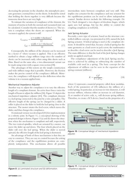
decreasing the pressure in the chamber, the atmospheric pressuregenerates a normal force on the sheets. It should be notedthat holding the sheets together is very difficult because thetransverse shear forces are very high.To estimate the variation <strong>of</strong> compliance <strong>of</strong> the element, themoment <strong>of</strong> inertia in both the normal and vacuumed state canbe calculated. Consider that the number <strong>of</strong> sheets is n. The systemis compliant when the sheets are separated. When thevacuum is applied, the system is stiff.n 3 width 3 thickness3I compliant ¼ (16)12width 3 (n 3 thickness)3I stiff ¼ (17)12Consequently, the stiffness <strong>of</strong> the element can be increasedby a factor n 2 when vacuum is applied. This is an effectivemethod to obtain a large stiffness range since the number <strong>of</strong>sheets can be increased easily when using thin sheets such asfilms. Based on the same idea, a two-dimensional variant canbe made using wires <strong>with</strong> a square cross section [38].The advantages <strong>of</strong> this system are the simple constructionand wide stiffness range that is possible. However, the frictionmakes the precise control <strong>of</strong> the compliance difficult. Moreover,the compliance will depend on the deflection when thevolume is in a vacuum applied state.Mechanical Impedance AdjusterAnother way to adjust the compliance is to vary the effectivelength <strong>of</strong> a compliant element. An active knee brace varies thelength <strong>of</strong> beam to adjust the stiffness [36]. Figure 10 depicts themechanical impedance adjuster [40]. The compliant elementis a leaf spring connected to the joint by a wire and pulley. Theeffective length <strong>of</strong> the spring can be changed by a slider. Aroller is placed on the slider to hold the leaf spring close to thestructure. The motor rotates the feed screw, which moves theslider, and thus changes the compliance.A rotational version was developed [41] for implementationin a robotic joint. In Figure 11, a conceptual drawing <strong>of</strong> theproposed design is shown. Figure 11(a) and (b) shows the situationwhen the mechanism is compliant and stiff, respectively.The two vertical spindles, which are actuated by a motor, canmove the slider up and down. The four wheels placed on theslider roll over the leaf spring. When the slider is movedupward, the effective length <strong>of</strong> the leaf spring is shortened.An advantage <strong>of</strong> both <strong>of</strong> these mechanisms is that they areeasy to construct. They are easy to control because the setting<strong>of</strong> the compliance and the equilibrium position are completelyindependent. This mechanism allows all possibleintermediate states between compliant and very stiff. Thisimplies one actuator for the compliance and one actuator forthe equilibrium position can be used to allow independentcontrol. Similar devices include the following example. DeUri Tasch designed a two-degree-<strong>of</strong>-freedom finger, whichagain uses leaf springs, but has the ability to control thecoupling compliance as well [42].Jack Spring ActuatorRecently, a new type <strong>of</strong> actuator, based on the structure controlledstiffness concept, was presented in [43], named the JackSpring actuator. A helical spring is used as the compliant element.It should be noted that, because a helical spring has thesame geometry as a lead screw or jack screw, the mathematicsto describe a lead screw can be used to describe a Jack Spring.The main difference is that the lead <strong>of</strong> the Jack Spring changesunder an applied axial load.The compliance adjustment <strong>of</strong> the Jack Spring mechanismis achieved by adding or subtracting the number <strong>of</strong>available coils used in a spring. The basic concept for theadjustment <strong>of</strong> stiffness can be seen in the equation <strong>of</strong> thespring constant (stiffness):K ¼Gd48 3 D 3 n a, (18)where G represents a material property called shear modulus.Each <strong>of</strong> the parameters <strong>of</strong> (18) influences the stiffness <strong>of</strong> acoiled spring. In particular, an increase in wire diameter, d, willincrease stiffness, whereas either an increase in coil diameter,D, or number <strong>of</strong> active coils, n a , will decrease spring stiffness.Therefore, to create a SCS device, based on the properties <strong>of</strong> aLeaf SpringMotorWireFeed ScrewTo JointSliderPulleyFigure 10. Conceptual design <strong>of</strong> mechanical impedanceadjuster.F(a)Figure 9. (a) Laminated structure and (b) deformation.(b)(a)Figure 11. Conceptual design <strong>of</strong> rotational mechanicalcompliance adjuster.(b)SEPTEMBER 2009 IEEE Robotics & Automation Magazine 89