Series E Installation Manual PDF - Myers Power Products, Inc.
Series E Installation Manual PDF - Myers Power Products, Inc.
Series E Installation Manual PDF - Myers Power Products, Inc.

You also want an ePaper? Increase the reach of your titles
YUMPU automatically turns print PDFs into web optimized ePapers that Google loves.
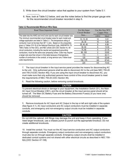
5. Write down the circuit breaker value that applies to your system from Table 5.1:__________6. Now, look at Table 5.2 below, and use the notes below to find the proper gauge wirefor the recommended circuit breaker recorded in step 5.Table 5.2 Recommended Minimum Wire SizesRead These Important Notes! For this Input Use this Size 90°CCircuit Breaker Copper WireSize...This table lists the AWG and mm2 wire size for each circuit breaker size.The minimum recommended circuit breaker sizes for each model andvoltage application are listed in Table 5.1. The temperature rating ofconductor must not be less than 90° C wire. Based on the ampacitiesgiven in Tables 310-16 of the National Electrical Code, ANSI/NFPA 70-1993 (Table 2 of the CEC), and NEC article 220 (CEC Section 4). Allcircuit conductors, including the neutral and equipment-groundingconductors, must be the same size (ampacity) wires. Code may requirea larger wire size than shown in this table because of temperature,number of conductors in the conduit, or long service runs. Follow localcode requirements.AWGMm210, 15, 20 12 3.3125, 30 10 5.2635, 40, 45 8 8.3650, 60 6 13.3070, 80 4 21.1590, 100 2 33.62110 1 42.11125 1/0 53.49150, 175 3/0 67.43225 4/0 74.407. The input circuit breaker in the input service panel provides the means for disconnecting ACto the unit. Only authorized persons shall be able to disconnect AC to the unit [see NEC 700-20and 700-21(CEC Section 46)]. If you are using the input circuit breaker to disconnect AC, youmust make sure that only authorized persons have control of the circuit breaker panel to meetthe requirements of NEC 700-20 (CEC Section 46).8. Read the following caution, before removing conduit knockouts.CAUTIONTo prevent electrical shock or damage to your equipment, the <strong>Installation</strong> Switch (S1), the MainAC Input Circuit Breaker (CB1), and the circuit breaker at the input service panel should all beturned off. The Main DC Battery Fuse and the Battery Disconnect Fuse(s) (if you have one)should be removed.9. Remove knockouts for AC Input and AC Output in the top or left and right side of the system(See figure 4.1). AC input conductors and AC output conductors must be installed in separateconduits, and emergency and non-emergency output circuits must be installed in separateconduits.CAUTIONDo not drill the cabinet; drill filings may damage the unit and keep it from operating. If youneed larger knockouts, use a chassis punch to punch out the appropriate knockout. Do notcreate additional knockouts.10. Install the conduit. You must run the AC input service conductors and AC output conductorsthrough separate conduits. Emergency output conductors and non-emergency output conductorsmust also be run through separate conduits. Emergency output circuits shall be installed indedicated conduit systems and not shared with other electrical circuits as described in NEC 700-9(b) [CEC Section 47-108].11114061 -System <strong>Installation</strong> <strong>Manual</strong>