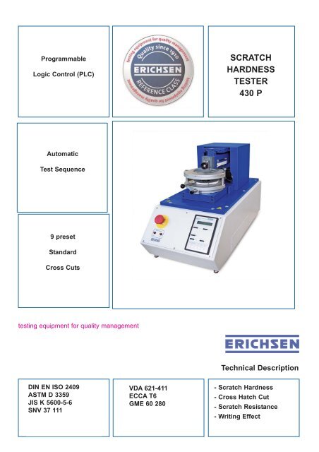
SCRATCH HARDNESS TESTER 430 P
SCRATCH HARDNESS TESTER 430 P
SCRATCH HARDNESS TESTER 430 P
- No tags were found...

Create successful ePaper yourself
Turn your PDF publications into a flip-book with our unique Google optimized e-Paper software.
ProgrammableLogic Control (PLC)<strong>SCRATCH</strong><strong>HARDNESS</strong><strong>TESTER</strong><strong>430</strong> PAutomaticTest Sequence9 presetStandardCross Cutstesting equipment for quality managementTechnical DescriptionDIN EN ISO 2409ASTM D 3359JIS K 5600-5-6SNV 37 111VDA 621-411ECCA T6GME 60 280- Scratch Hardness- Cross Hatch Cut- Scratch Resistance- Writing Effect
<strong>SCRATCH</strong> <strong>HARDNESS</strong> <strong>TESTER</strong> <strong>430</strong> PPurpose and ApplicationThe motor-driven <strong>SCRATCH</strong> <strong>HARDNESS</strong><strong>TESTER</strong> <strong>430</strong> P is a universal testing instrumentdesigned for carrying out a wide range of tests onvarnished and plastic surfaces to determine theirresistance to scratches and cuts. Single cuts,parallel cuts and - by turning the specimen by 90°- cross-cuts can be applied to test panels ofvarious thicknesses.The <strong>SCRATCH</strong> <strong>HARDNESS</strong> <strong>TESTER</strong> <strong>430</strong> P isparticularly provided for adhesion tests using thecross hatch cut method (in accordance with allmostly required standards) and for specificplastics tests according with Opel (scratchresistance and writing effect). For these as well asfor further tests numerous setting possibilites onthe basic instrument and a large variety of testtools are available.Using the <strong>SCRATCH</strong> <strong>HARDNESS</strong> <strong>TESTER</strong><strong>430</strong> P, series testing can be conducted with muchgreater ease. The results of testing arereproducible and well-defined.Design and FunctionThe <strong>SCRATCH</strong> <strong>HARDNESS</strong> <strong>TESTER</strong> <strong>430</strong> P is abenchtop instrument of sound mechanicalconstruction which provides reliable, well-definedcuts, even under extreme test conditions. The testprocedure is carried out automatically and allparameters (cutting speed, cutting stroke, crosscutpattern) can be set using the keyboard. Eachmotion sequence (transport of test panel, cutpositioning and any required pressure adjustment)is driven by a separate step motor.During the test the specimen is conveyed linearlyand at a constant speed under the test tip whichhas been set at the required pressure load (max.40 N). A transmission guide ensures that the testtip is lowered onto the test panel as defined. Thescope of supply includes two control plates fordifferent cross-cut patterns which can be easilyinterchanged.With Model <strong>430</strong> P parallel cross hatch cuts withgraduated test forces are possible. After carryingout the first cross hatch cut the instrument can bestopped and the test force (up to 50 N) can be adjustedindividually before starting the next testtrack.Theoretically, 80 test tracks with a distanceof 0.5 mm of different test forces are possiblewithin the pre-selected cross hatch cutprogramme.The <strong>SCRATCH</strong> <strong>HARDNESS</strong> <strong>TESTER</strong> <strong>430</strong> P ispower-driven and obtainable in two versions - withmanual or with motor-driven force regulation. Onthe manual version it is a simple matter to adjustthe test force to the exact pressure. Theinstrument with motor-driven force regulationprovides the additional benefit of conducting a trialrun with gradually increasing force. In this way,the force required to achieve a through cut can beautomatically ascertained in the course of a "trialcut".A 6-piece weight set is available as an optionalaccessory for conducting special tests in the lowerpressure range and enables cuts with test forcesin the range (1 - 15) N - graduated in 1-N steps.Special Features• 2 cutting speeds and 2 cutting lengths whichcan be combined as required• 9 preset cross-cuts in compliance with themost commonly used standards• 1 freely programmable cross-cut pattern forspecial applications• Setting for cut distance with step motor precision• "Stop"-option within the cross hatch cuttingmode, for individually changing the test forcefor the next scratch track of the concerningcurrent cross-cut pattern• Visual display upon cutting through insulatinglayers to metal substrate• Rapid clamping device for test panels, withwide clamping range.Cross Hatch TestingThe <strong>SCRATCH</strong> <strong>HARDNESS</strong> <strong>TESTER</strong> <strong>430</strong> Penables cross hatch tests to be conducted inaccordance with all the usual standards,summarized in the following table, and carried outimmediately without additional programming. Thefollowing cross-cuts can be selected by pressing akey (number of cuts x distance in mm betweencuts) 2 x 5, 6 x 1, 6 x 2, 6 x 3, 8 x 1, 8 x 2, 11 x 1.The cuts are carried out automatically insuccession using the test tip for cross hatch at acutting speed of 40 mm/s. After turning the testpanel manually by 90°, the procedure is repeatedto complete the cross-cut pattern. The loadrequired to ensure that the layer of varnish will becut through to the substrate must be ascertainedin trial runs. With Model <strong>430</strong> P-II (motor-drivenforce adjustment) this can be carried out verysimply by performing a "trial cut".For the examination of cross hatch cuts amagnifiying glass with 2.5 magnification is includedin the scope of supply. To evaluate thecross hatch pattern achieved, it is visually relatedto a comparison pattern within a scheme indicatedin the relevant standard (cross cut classification).In ECCA T6 it is mentioned that the cross hatchcut test may be intensified by a subsequentcupping test according to DIN EN ISO 1520. Forthis purpose we recommend the ERICHSENLacquer and Paint Testing Machines, models 200and 202 C.Although the results of adhesion tests inaccordance with the cross hatch method arecomparable with each other, they are - due to theirrespective procedures - not transferable to resultsof alternative test methods (e.g. perpendicularpull-off test according to DIN EN ISO 4624).
<strong>SCRATCH</strong> <strong>HARDNESS</strong> <strong>TESTER</strong> <strong>430</strong> PThe ERICHSEN production programme offers thefollowing model for adhesion testing to the pull-offmethod:• Adhesion Test Apparatus, Model 525(manual / inexpensive)Standard Layer thickness No. of cuts x distance (mm)DIN EN ISO 2409 up to 60 µm6 x 1 (for soft substrates)6 x 2 (for hard substrates)6 x 26 x 3JIS K 5600-5-6 over 60 µm to 120 µmover 120 µm to 250 µmASTM D 3359 up to 50 µmover 50 µm to 125 µmSNV 37111 up to 60 µmover 60 µmup to 60 µmVDA 621-411over 60 µm to 120 µmover 120 µmECCA T6 up to 50 µmover 50 µmCross Hatch Standards11 x 16 x 28 x 18 x 26 x 16 x 26 x 36 x 12 x 5Scratch Resistance TestingFor testing scratch resistance in accordance withOpel (GME 60280 / GMW14688) the test tip witha 1 mm ∅ is selected together with the preset grid"20 cuts at a distance of 2 mm" (20 x 2). Thestress pattern in this case is applied with a testload of 5 N (set of weights) by the sameprocedure as for the cross hatch test (cuttingspeed 1m/min).To analyse the scratch resistance test thebrightness variance (ΔL) is determined incomparison with the plastic surface which is notsubjected to strain. The colour measuring deviceto be used for this purpose must fulfil the followingrequirements: illuminant D65, measuringgeometry d/8 with gloss exclusion, measuringaperture ∅ 27 mm.Writing Effect TestingFor testing the writing effect in accordance withOpel the test inset offered as optional accessory,is required. This inset has to be mounted on theload arm instead of the tool holder. The stresspattern is applied with the preset grid "80 cuts at adistance of 0.5 mm" (80 x 0.5) and a test load of7 N (set of weights) analogue to the cross hatchtest (cutting speed 1 m/min).To evaluate the result of the writing effect test thegloss difference is determinded in comparisonwith the plastic surface not subjected to strain.The gloss meter used should be provided with a60° geometry; the measuring area must be smallenough to allow carrying out reproducible glossmeasurements on the surface subjected to strain.For this test purpose all the ERICHSENglossmeters of the PICOGLOSS family are highlyrecommended.Special TestsDeviating from the determinations of the abovementioned tests (cross hatch test, scratchresistance, writing effect) further scratch tests canbe carried out varying the following parameters:• Test tip- ball test tool ∅ 0.5 / 0.75 / 1 / 3 mm- asymmetric test tools: cross cut / Clemen• Test load- rough range 50 N with 2 N graduation (standard)- fine range 15 N in 1 N steps (optional)• Cutting grid- preset, selectable by depression of key: 2 x 5,6 x 1, 6 x 2, 6 x 3, 8 x 1, 8 x 2, 11 x 1, 20 x 2,80 x 0.5 (number of cuts x distance in mm)- freely programmable: all grids max. width40 mm and a multiple of 0.5 mm as cuttingdistance.• Cutting pattern- parallel cuts or cross cuts• Cutting path- 25 mm or 40 mm (exchangeable guide plates)• Cutting speed- 16.7 mm/s (1 m/min) or 40 mm/sIn order to minimize testing time, the smallestpossible length of cut is always selected, togetherwith the relevant connecting member.
<strong>SCRATCH</strong> <strong>HARDNESS</strong> <strong>TESTER</strong> <strong>430</strong> PTechnical DataDimensions (W x H x D)Net weightPower supply 1)ConsumptionTest panel format, min.Test panel format, max.Thickness of specimenStandard load rangeSpecial load range 2)Cutting pathCutting speed1)2)330 x 460 x 750 mmapprox. 40 kg230 VAC / 50 Hz400 W80 x 50 mm165 mm wide,any length0.5 - 20 mm2 - 50 N (2-N grading)1 - 15 N (1-N grading)25 or 40 mm1 m/min or 40 mm/salternatively 115 VAC / 60 Hz(please specify mains supply when ordering)Optional set of weights for bottom load rangeReference Class:Both versions of the <strong>SCRATCH</strong> <strong>HARDNESS</strong><strong>TESTER</strong> <strong>430</strong> P are supplied with aManufacturer’s Certificate M in accordance withDIN 55 350-18 that includes among others thefollowing information:Actual and setting values of loading force,scratching speed and cutting distance, testequipments used with calibration status, productindentification, date, name of inspector.Comparisons of the setting/actual values for thefollowing parameters are made:- Loading force (5 setting values evenlydistributed over the load range- Cutting speed (both desired values incombination with both cutting paths)- Cutting distance (exemplary for setting value0.5 mm).Order No..Order InformationProduct Description0190.01.31 <strong>SCRATCH</strong> <strong>HARDNESS</strong> <strong>TESTER</strong><strong>430</strong> P-Imotor-driven turntable and cuttingposition and with manual adjustment ofloading force, manual turning of testpanels and control plate for cutting pathof 40 mmLoad pressure max. 50 N0190.02.31 <strong>SCRATCH</strong> <strong>HARDNESS</strong> <strong>TESTER</strong><strong>430</strong> P-IIas for Order No. 0190.01.31, but withmotor-driven adjustment of loadingforceIncluded in scope of supply:¨ Transport case with- 3 Allen keys (SW 2 / 2.5 / 3)- Connecting member for cutting path of 25 mm- Folding magnifier (2.5 fold magnification)- Recesses for set of weights, test inset(writing effect) and for max. 8 test tips¨ Mains connection cable¨ Operating instructionsCaution:• Test tips are not included in the scope of supply• Please specify mains supply when orderingAccessories / SparesOrder No.Description of Product0564.01.32 Test tip for cross hatch 1)0539.01.32 Test tip acc. to van Laar (∅ 0.5 mm) 2)0539.02.32 Test tip acc. to Bosch (∅ 0.75 mm) 2)0539.03.32 Test tip acc. to ISO 1518 (∅ 1.0 mm) 2)0539.04.32 Test tip (∅ 3.0 mm) 1)0218.02.32 Test tip acc. to Clemen 2)0539.05.32 Test inset for writing effect0<strong>430</strong>.03.32 Test disc for writing effect0567.01.32 Set of weights for bottom load range(6 pcs.)1) hardened steel2) equipped with hard metalSubject to technical modification.Gr. 12 - TBE <strong>430</strong> P – XI/2009
Spherical InsertsAsymmetric InsertsDescription Test geometry MaterialDescription Test geometry Materialtest tipacc. to van1) 2)Laartest tipacc. to1) 2)Clementest tipacc. to IHD 1)carbide inserttest tipacc. to VW 1)carbide inserttest tipacc. to Bosch 2)test tipacc. toSikkens 1)test tipacc. to ISO 1) 2) carbide insert * )test tipacc. toSikkens 1)test tipacc. to BMW 2)hardenedsteeltest tip forcross hatchcutting 2)hardenedsteel *)* ) additionally covered with an extremly hard layer1)long shaft, directly assembled2)3)short shaft, only for using with the adapter setonly for using with the disc adapter of the universaladapter setduroplasttest discacc. tocopperOesterle 3) stainless steelstainless steel *)Technical DataDimensions (L x W x H)580 mm x 280 mm x 210 mmSpecimen dimensions max. 150 mm x 210 mm (DIN A 5)Power supply(100 - 240) VAC, (47 - 63) HzNet weightapprox. 13 kgScratching force(0.5 – 20) NMedium test speed22/35/200 mm/s (fixed)(20 – 200) mm/s programmableLength of cycle60/110 mm (with/without guide plate)
Universal Adapter SetIn addition to the standard range of test tools the Universal Adapter Set allows the use of a variety of additions toolinserts. In this way individual test problems with specific tool geometries deviating from established determinations canbe solved in an easy manner. The adapter set consists of the following components:Universal shaftRound rod (5 mm diameter) made of stain-lesssteel, with an axial bore with internal thread(M2.5) at one end and a clamping area overthe total length. The universal shaft is mountedon the load arm vertically; there the adapterdescribed here-after can be fixed.Clamping adapterCylindrical part made of stainlesssteel, with one axial boreeach of 4 mm and 5 mm diameteras well as radialthreaded bores with clampingscrews. The clamping adapteris intended for tool insertsusing a cylindrical shaft (4 mmdia.).Disc adapterCylindrical part made of stainlesssteel with axial bore (5 mm dia.)and radial threaded bores withclamping screws at one end; atthe other end plane millingparallel to the axis with threeradial threaded bores (M3). Thedisc adapter serves for fixing ofplane tool inserts, especially suchwith circular letter disc geometry.Chucking adapterClamping huck made ofgunmetal finish steel with threepiececollet chuck se for 1/2.35/3 mm dia. The chucking adapterserves as a support for acylindrical tool insert withspherical or pointed tip (pins,needles etc.).Direct assemblyGauge slide with outsidethread M2.5 (e.g. probetip)Subject to technical modifications.Group 14 - TBE 249 – XII/2009