ECODRIVE DKC03.1 Drive Controller - Bosch Rexroth
ECODRIVE DKC03.1 Drive Controller - Bosch Rexroth
ECODRIVE DKC03.1 Drive Controller - Bosch Rexroth

You also want an ePaper? Increase the reach of your titles
YUMPU automatically turns print PDFs into web optimized ePapers that Google loves.
274132<br />
engineering<br />
mannesmann<br />
<strong>Rexroth</strong><br />
<strong>ECODRIVE</strong><br />
<strong>DKC03.1</strong> <strong>Drive</strong> <strong>Controller</strong><br />
Functional Description: PDP03VRS<br />
DOK-ECODRV-PDP-03VRS**-FKB1-EN-P<br />
Indramat
Title<br />
Document Type Description<br />
Document Type<br />
Internal Filing Notation<br />
What is the purpose of this<br />
documentation?<br />
Change Notice<br />
Copyright<br />
Liability<br />
Publisher<br />
DOK-ECODRV-PDP-03VRS**-FKB1-EN-P • 11.96<br />
<strong>ECODRIVE</strong> <strong>DKC03.1</strong> <strong>Drive</strong> <strong>Controller</strong><br />
Functional Description<br />
DOK-ECODRV-PDP-03VRS**-FKB1-EN-P<br />
• Map 58-03V-EN Register 3<br />
• 209 0073-4312-01<br />
• Based on: 03V06<br />
<strong>ECODRIVE</strong> <strong>DKC03.1</strong> <strong>Drive</strong> <strong>Controller</strong><br />
The following document describes the functions of the firmware FWA-<br />
ECODRV-PDP-03VRS-MS in connection with <strong>Drive</strong>Top 03V03<br />
The document serves:<br />
• to describe all functional characteristics<br />
• for setting parameters for the drive controller<br />
• for data security of the drive parameters<br />
• for error diagnosis and troubleshooting<br />
Document identification of<br />
previous and current releases<br />
Release<br />
date<br />
Remarks<br />
DOK-ECODRV-PDP-03VRS**-FKB1-EN-P 11.96 First release<br />
© INDRAMAT GmbH, 1996<br />
Distribution and reproduction of this documentation, commercial use or<br />
communication of its contents are not permitted without express written<br />
permission. Violation of these stipulations will require compensation. All<br />
rights reserved for the issuance of the patent or registered design.<br />
(DIN 34-1)<br />
We reserve the right to make changes to the contents of the<br />
documentation and the availability of products.<br />
INDRAMAT GmbH • Bgm.-Dr.-Nebel-Str. 2 • D-97816 Lohr a. Main<br />
Telephone 09352/40-0 • Tx 689421 • Fax 09352/40-4885<br />
Dpt. END (OS)
Contents<br />
<strong>ECODRIVE</strong> <strong>DKC03.1</strong> <strong>Drive</strong> <strong>Controller</strong><br />
1 System Overview 1-1<br />
1.1 Ecodrive - The Economical Control <strong>Drive</strong> for Automation.................................................................... 1-1<br />
1.2 Ecodrive - A Family of <strong>Drive</strong> <strong>Controller</strong>s .............................................................................................. 1-1<br />
1.3 Overview of Functions <strong>DKC03.1</strong>.......................................................................................................... 1-2<br />
<strong>DKC03.1</strong> - Modes of Operation..................................................................................................... 1-2<br />
General Features of <strong>DKC03.1</strong>....................................................................................................... 1-3<br />
2 Safety Instructions for Electrical <strong>Drive</strong> <strong>Controller</strong>s 2-1<br />
2.1 General Information ............................................................................................................................. 2-1<br />
2.2 Protection against Contact with Electrical Components ...................................................................... 2-2<br />
2.3 Protection of Safely Separated Low Voltages...................................................................................... 2-3<br />
2.4 Protection from Dangerous Motion ...................................................................................................... 2-3<br />
2.5 Protection During Assembly and Handling........................................................................................... 2-5<br />
3 Preparation for Startup Procedure 3-1<br />
3.1 General Instructions for Startup Procedure ......................................................................................... 3-1<br />
3.2 <strong>Drive</strong>Top Startup Procedure and Diagnostics...................................................................................... 3-1<br />
3.3 <strong>Drive</strong>Top-System Requirements.......................................................................................................... 3-1<br />
3.4 Installation of <strong>Drive</strong>Top ........................................................................................................................ 3-2<br />
Starting the Installation Program................................................................................................... 3-2<br />
Setting Communications Parameters ........................................................................................... 3-3<br />
3.5 Connection of the PC with the <strong>Drive</strong> controller .................................................................................... 3-5<br />
3.6 Minimal Installation for Operating a DKC with <strong>Drive</strong>Top...................................................................... 3-6<br />
3.7 <strong>Drive</strong>Top Startup.................................................................................................................................. 3-7<br />
Scanning for Connected <strong>Drive</strong>s .................................................................................................... 3-7<br />
Online and Offline Operation......................................................................................................... 3-8<br />
Diagnostic Window........................................................................................................................ 3-9<br />
Password Protection ................................................................................................................... 3-10<br />
3.8 <strong>Drive</strong>Top Menu Structure................................................................................................................... 3-13<br />
Files............................................................................................................................................. 3-13<br />
Parameter ................................................................................................................................... 3-13<br />
Setup <strong>Drive</strong>.................................................................................................................................. 3-14<br />
<strong>Drive</strong> ............................................................................................................................................ 3-14<br />
Options........................................................................................................................................ 3-15<br />
Help ............................................................................................................................................. 3-15<br />
3.9 Printing Parameter Data..................................................................................................................... 3-16<br />
4 Motor and <strong>Drive</strong> <strong>Controller</strong> Selection 4-1<br />
4.1 General Information on Selecting a Motor and <strong>Drive</strong> <strong>Controller</strong> .......................................................... 4-1<br />
4.2 Motor Selection .................................................................................................................................... 4-1<br />
DOK-ECODRV-PDP-03VRS**-FKB1-EN-P • 11.96 Contents I
<strong>ECODRIVE</strong> <strong>DKC03.1</strong> <strong>Drive</strong> <strong>Controller</strong><br />
4.3 <strong>Drive</strong> <strong>Controller</strong> Selection .................................................................................................................... 4-3<br />
Selecting the <strong>Drive</strong> <strong>Controller</strong>........................................................................................................ 4-3<br />
Selecting the Overload Factor....................................................................................................... 4-4<br />
Selecting the PWM Frequency...................................................................................................... 4-4<br />
Setting the Operation Mode: Position Control with Positioning Interface ...................................... 4-5<br />
Position Control with Following Error ............................................................................................ 4-5<br />
Position Control without Following Error ....................................................................................... 4-5<br />
Selecting the Appropriate Position Control Mode.......................................................................... 4-5<br />
5 Control Communication Via the Profibus DP 5-1<br />
5.1 Features of the Profibus Device........................................................................................................... 5-1<br />
5.2 <strong>Drive</strong> Control Word .............................................................................................................................. 5-2<br />
5.3 <strong>Drive</strong> Status Word................................................................................................................................ 5-3<br />
5.4 Installation Procedure .......................................................................................................................... 5-4<br />
Turn on the <strong>DKC03.1</strong> .................................................................................................................... 5-4<br />
Turning the Power Supply On and Off. ......................................................................................... 5-5<br />
5.5 Control Functions That Can Be Initiated from the Profibus.................................................................. 5-6<br />
5.6 Profibus Connection............................................................................................................................. 5-6<br />
Cable ............................................................................................................................................. 5-6<br />
Connections and Wiring................................................................................................................ 5-6<br />
Diagnostic message LED.............................................................................................................. 5-7<br />
Address switch .............................................................................................................................. 5-7<br />
6 <strong>DKC03.1</strong> <strong>Drive</strong> <strong>Controller</strong> with Integrated Position Control 6-1<br />
6.1 General Information for Operating with Position Control ..................................................................... 6-1<br />
6.2 Positioning Block Input......................................................................................................................... 6-2<br />
Block Number................................................................................................................................ 6-2<br />
Positioning Block Data .................................................................................................................. 6-3<br />
6.3 Positioning Operation........................................................................................................................... 6-5<br />
Absolute Positioning...................................................................................................................... 6-5<br />
Relative Positioning....................................................................................................................... 6-6<br />
Continuous Motion in Positive/Negative Direction....................................................................... 6-11<br />
Following Block Operation........................................................................................................... 6-12<br />
6.4 Choosing, Starting and Selecting a Positioning block........................................................................ 6-17<br />
Choosing a Positioning Cblock.................................................................................................... 6-17<br />
Starting Positioning Blocks.......................................................................................................... 6-17<br />
Interrupting Positioning Blocks.................................................................................................... 6-17<br />
Acquittance of Positioning Block Selection with <strong>Drive</strong> Enable Active.......................................... 6-18<br />
Acknowledgement When <strong>Drive</strong> Enable is Switched Off.............................................................. 6-20<br />
6.5 Target Position Processing with Modulo Scaling ............................................................................... 6-21<br />
7 General <strong>Drive</strong> Functions 7-1<br />
7.1 Scaling and Mechanical System Data.................................................................................................. 7-1<br />
Linear Scaling................................................................................................................................ 7-1<br />
Rotary Scaling ............................................................................................................................... 7-3<br />
Processing Position Data .............................................................................................................. 7-4<br />
7.2 <strong>Drive</strong> limits............................................................................................................................................ 7-6<br />
Transverse Range Limits .............................................................................................................. 7-6<br />
II Contents DOK-ECODRV-PDP-03VRS**-FKB1-EN-P • 11.96
<strong>ECODRIVE</strong> <strong>DKC03.1</strong> <strong>Drive</strong> <strong>Controller</strong><br />
Limiting the Velocity ...................................................................................................................... 7-8<br />
Torque Limit .................................................................................................................................. 7-8<br />
7.3 Error Handling ...................................................................................................................................... 7-9<br />
7.4 Control Loop Settings......................................................................................................................... 7-10<br />
General Information for Control Loop Settings............................................................................ 7-10<br />
Loading Default Parameters ....................................................................................................... 7-11<br />
Executing the Basic Load Feature After Changing Motor or <strong>Drive</strong> ............................................. 7-11<br />
Executing the Basic Load Feature as a Command in the "Control Loop Setting" Dialog ........... 7-12<br />
Setting the Current Regulator...................................................................................................... 7-13<br />
Setting the Speed <strong>Controller</strong> (Velocity Loop) .............................................................................. 7-14<br />
7.5 Loop Monitoring ................................................................................................................................. 7-18<br />
Velocity Loop Monitoring ............................................................................................................. 7-19<br />
Position Loop Monitoring............................................................................................................. 7-20<br />
7.6 Status Messages................................................................................................................................ 7-21<br />
Ready for Operation (bb)............................................................................................................. 7-21<br />
In Position (INPOS)..................................................................................................................... 7-22<br />
In Motion (INBWG)...................................................................................................................... 7-23<br />
In Reference (INREF) ................................................................................................................. 7-23<br />
Position Switch Point (WSP) ....................................................................................................... 7-23<br />
Profibus status word.................................................................................................................... 7-24<br />
7.7 <strong>Drive</strong>-controlled homing procedure.................................................................................................... 7-25<br />
Homing When Using a Motor With Resolver Feedback (Standard) ........................................... 7-25<br />
Homing When Using a Motor With Integrated Absolute Encoder Function (Optional) ............... 7-31<br />
7.8 Jogging............................................................................................................................................... 7-34<br />
7.9 Positioning at Limited Velocity............................................................................................................ 7-35<br />
Function....................................................................................................................................... 7-35<br />
Applications ................................................................................................................................. 7-35<br />
Example ...................................................................................................................................... 7-36<br />
Parameter ................................................................................................................................... 7-36<br />
Activation..................................................................................................................................... 7-36<br />
7.10 Feedrate Override Feature............................................................................................................... 7-37<br />
7.11 Analog Output .................................................................................................................................. 7-37<br />
7.12 Motor brake...................................................................................................................................... 7-39<br />
7.13 Activating the <strong>Drive</strong> .......................................................................................................................... 7-41<br />
<strong>Controller</strong> Enable......................................................................................................................... 7-41<br />
<strong>Drive</strong> Stop/Start ........................................................................................................................... 7-41<br />
E-Stop Function........................................................................................................................... 7-42<br />
<strong>Controller</strong> Enable, <strong>Drive</strong> Halt and E-Stop Signal Connections.................................................... 7-42<br />
8 Serial Communication 8-1<br />
8.1 General Information for Serial Communication.................................................................................... 8-1<br />
8.2 Communication via the RS232 Interface ............................................................................................. 8-1<br />
8.3 Communication via the RS485 Interface ............................................................................................. 8-2<br />
Operating of Multiple <strong>Drive</strong>s with DRIVETOP ............................................................................... 8-2<br />
Diagnostic Messages and Setting Parameters via a PLC............................................................. 8-3<br />
Diagnostics and Setting Parameters of <strong>Drive</strong> Groups Through an Operator Interface................. 8-4<br />
8.4 Communication Procedures................................................................................................................. 8-5<br />
Communication Parameters ......................................................................................................... 8-5<br />
DOK-ECODRV-PDP-03VRS**-FKB1-EN-P • 11.96 Contents III
<strong>ECODRIVE</strong> <strong>DKC03.1</strong> <strong>Drive</strong> <strong>Controller</strong><br />
Setting the <strong>Drive</strong> Address.............................................................................................................. 8-6<br />
Original State after Establishing the Control Voltage .................................................................... 8-6<br />
Communication with a Specific Bus Unit....................................................................................... 8-6<br />
Parameter Structure...................................................................................................................... 8-7<br />
Writing To a Parameter................................................................................................................. 8-7<br />
Reading a Parameter .................................................................................................................... 8-8<br />
Writing to a List Parameter ........................................................................................................... 8-8<br />
Reading a List Parameter ............................................................................................................. 8-8<br />
Executing Parameter Commands ................................................................................................. 8-9<br />
Requesting the Status of a Command .......................................................................................... 8-9<br />
Ending a Parameter Command................................................................................................... 8-10<br />
Error Messages........................................................................................................................... 8-11<br />
8.5 Application Examples......................................................................................................................... 8-12<br />
Changing Positioning Block Data................................................................................................ 8-12<br />
8.6 Connections ....................................................................................................................................... 8-13<br />
RS485 Connection ...................................................................................................................... 8-13<br />
RS 232 Connection ..................................................................................................................... 8-14<br />
9 Index 9-1<br />
Supplement A: Parameter description<br />
Supplement B: Diagnostic message description<br />
Directory of Customer Service Locations<br />
IV Contents DOK-ECODRV-PDP-03VRS**-FKB1-EN-P • 11.96
1 System Overview<br />
<strong>ECODRIVE</strong> <strong>DKC03.1</strong> <strong>Drive</strong> <strong>Controller</strong><br />
1.1 Ecodrive - The Economical Control <strong>Drive</strong> for Automation<br />
<strong>ECODRIVE</strong> is a digital intelligent automation system which provides a<br />
cost effective way to control single and multiple axis control tasks.<br />
<strong>ECODRIVE</strong> can be used to accomplish all kinds of control tasks in<br />
different fields. It is typically used in applications such as:<br />
• Handling systems<br />
• Packaging machinery<br />
• Assembly systems<br />
1.2 Ecodrive - A Family of <strong>Drive</strong> <strong>Controller</strong>s<br />
An <strong>ECODRIVE</strong> consists of a drive controller and an MKD servomotor.<br />
There are presently four drive controllers available, each with different<br />
control interfaces.<br />
• DKC01.1 with analog, stepping motor and<br />
Positioning interfaces<br />
• DKC11.1 with Analog interface<br />
• DKC02.1 with SERCOS interface<br />
• <strong>DKC03.1</strong> with PROFIBUS-DP interface<br />
This description of functions refers to the <strong>DKC03.1</strong>. Separate<br />
documentation is available for the DKC01.1 and the DKC02.1.<br />
DOK-ECODRV-PDP-03VRS**-FKB1-EN-P • 11.96 System Overview 1-1
<strong>ECODRIVE</strong> <strong>DKC03.1</strong> <strong>Drive</strong> <strong>Controller</strong><br />
1.3 Overview of Functions <strong>DKC03.1</strong><br />
<strong>DKC03.1</strong> - Modes of Operation<br />
Memory-programmable<br />
control<br />
PROFIBUS-DP-<br />
-interface<br />
Selection of<br />
positioning<br />
blocks<br />
MS-DOS ® - PC<br />
Parameters<br />
Diagnostics<br />
Operating data<br />
PROFIBUS-DP-<br />
-interface<br />
Servo drive with integrated positioning control<br />
RS 232<br />
RS 485<br />
Stored<br />
positioning<br />
blocks<br />
2°<br />
2 1<br />
2 2<br />
2 3<br />
2 4<br />
2 5<br />
position 1<br />
position<br />
. 2<br />
position 64<br />
<strong>DKC03.1</strong> drive controller<br />
with PROFIBUS-DP interface<br />
<strong>Drive</strong> computer<br />
Fine interpolation<br />
Position control<br />
Velocity control<br />
Field-oriented<br />
stator current<br />
control<br />
High-resolution<br />
position interface<br />
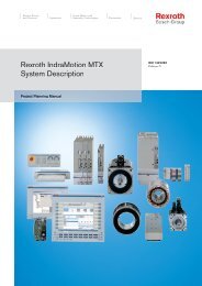
Fig. 1-1: Servo drive with integrated positioning control<br />
AC Servo motor<br />
MKD<br />
1-2 System Overview DOK-ECODRV-PDP-03VRS**-FKB1-EN-P • 11.96<br />
M<br />
3~<br />
~ ~<br />
FS0203D4<br />
• Up to 64 positioning blocks can be stored in the <strong>DKC03.1</strong>. They can<br />
be accessed via 6 bits in the profibus control word. The <strong>DKC03.1</strong><br />
executes position blocks independently.<br />
• The drive controller can conform to mechanical transmission elements<br />
such as gear ratios or feed constants.<br />
• All position, speed, and acceleration data can be scaled rotary or linear<br />
depending on the axial kinetics.<br />
• An internal homing procedure can be used to create a reference<br />
position.<br />
• The axis can be controlled via the jog function for set-up operation.<br />
• The positioning velocity can be limited to a uniform value.<br />
• Limit switch inputs and adjustable parameter position limits are<br />
available to set travel range limits.<br />
• The drive controller status can be determined via status outputs.
General Features of <strong>DKC03.1</strong><br />
Direct Power Supply Connection<br />
<strong>ECODRIVE</strong> <strong>DKC03.1</strong> <strong>Drive</strong> <strong>Controller</strong><br />
The drive controllers can be attached directly to three-phase power<br />
supplies with from 380 V to 480 V, without a transformer. Power rectifiers,<br />
intermediate circuit capacitors, brake resistances and bleeders are<br />
included as standard equipment.<br />
Integrated Brake Activation<br />
The optional brake in MKD motors is activated directly via the drive<br />
controller.<br />
Actual Position Value Measurement<br />
<strong>ECODRIVE</strong> measures the actual position value via the motor feedback<br />
system<br />
• Incremental position measurement (standard)<br />
The actual position value will be set at a random value when the power<br />
supply is first turned on. To give the actual position value a fixed<br />
reference point, the reference point must be set with a defined homing<br />
procedure.<br />
• Absolute position measurement (optional)<br />
After the power supply has been turned on, the absolute actual<br />
position value in relation to a fixed reference point is immediately<br />
available. Thus, completing the homing procedure is unnecessary.<br />
Integrated Diagnostic Display<br />
All internal state and error analysis is displayed via a two digit sevensegment<br />
display.<br />
Easy Installation<br />
The <strong>Drive</strong>Top installation and diagnostic program provides you with userfriendly<br />
installation via the serial RS-232 interface on a PC running<br />
Windows TM 3.1.<br />
DOK-ECODRV-PDP-03VRS**-FKB1-EN-P • 11.96 System Overview 1-3
<strong>ECODRIVE</strong> <strong>DKC03.1</strong> <strong>Drive</strong> <strong>Controller</strong><br />
Notes<br />
1-4 System Overview DOK-ECODRV-PDP-03VRS**-FKB1-EN-P • 11.96
<strong>ECODRIVE</strong> <strong>DKC03.1</strong> <strong>Drive</strong> <strong>Controller</strong><br />
2 Safety Instructions for Electrical <strong>Drive</strong> <strong>Controller</strong>s<br />
2.1 General Information<br />
• The safety information in this user's manual must always be observed.<br />
• Improper use of this device and disregard for the warnings which are<br />
given can lead to damaging the device, injury, or, in extreme cases,<br />
death.<br />
• In case of damage due to neglecting the warnings in this user's<br />
manual, INDRAMAT GmbH does not assume any liability.<br />
• If you do not understand the documentation in this language, request it<br />
in another language you will understand before proceeding with the<br />
startup procedure.<br />
• The accurate and safe operation of this device requires proper<br />
transport, safe storage, assembly and installation as well as careful<br />
servicing and maintenance.<br />
• Use only manufacturer-authorized replacement parts.<br />
• Follow the safety instructions and specifications for the operations<br />
stated.<br />
• The devices are designed for installation in machines that will be used<br />
in industrial applications.<br />
• Installation is prohibited until it is shown that the machine in which the<br />
device is installed complies with EG Standard 89/ 392/ EWG (machine<br />
standards).<br />
• Operation is allowed only when the national EMV regulations for the<br />
following applications are observed. In the EU, the EMV standard 89/<br />
336/ EWG must be observed.<br />
• The technical data, connection requirements and the installation<br />
requirements are found within the user's manual and must be<br />
followed.<br />
Qualified Personnel:<br />
• Only qualified personnel should work on this device or work within the<br />
area of this device.<br />
• Persons are qualified if they are sufficiently experienced with<br />
assembly, installation and operation of the product as well as all of the<br />
warnings and precautions as described in the user's manual.<br />
• Furthermore, he or she must have been taught or authorized to turn on<br />
and off, ground, and designate the current carrying circuits and<br />
devices in accordance with generally accepted safety techniques.<br />
He/she must have appropriate safety equipment and be trained in first<br />
aid.<br />
DOK-ECODRV-PDP-03VRS**-FKB1-EN-P • 11.96 Safety Instructions for Electrical <strong>Drive</strong> <strong>Controller</strong>s 2-1
<strong>ECODRIVE</strong> <strong>DKC03.1</strong> <strong>Drive</strong> <strong>Controller</strong><br />
2.2 Protection against Contact with Electrical Components<br />
Explanation:<br />
Parts with a voltage greater than 50 volts can be dangerous for human<br />
contact. When electrical devices are in operation certain parts always<br />
have a dangerous voltage.<br />
DANGER<br />
High voltage!<br />
Life threatening or serious bodily harm<br />
⇒ The general assembly and safety instructions must<br />
be followed when working in high voltage area.<br />
⇒ After the installation of the drive controller to all<br />
electrical devices, re-check the connection<br />
schematic.<br />
⇒ Even if an operation will only last for a short period of<br />
time, or is for test purposes only, it should only be<br />
undertaken if protective earth conductor is securely<br />
attached to the points provided for it on the<br />
components.<br />
⇒ Before servicing electrical components with a voltage<br />
higher than 50 volts, disconnect the device from the<br />
power source. Ensure that it will not be turned back<br />
on.<br />
⇒ Wait for 5 minutes after the device has been turned<br />
off before handling it so that the capacitors can<br />
completely discharge.<br />
⇒ Do not touch the components' electrical connector<br />
plugs while the device is on.<br />
⇒ Before turning on the device, cover the parts which<br />
are under voltage in order to avoid them being<br />
touched.<br />
⇒ An FI circuit breaker (earth leakage circuit breaker)<br />
cannot be used for AC-drives! The protection against<br />
indirect touching must be produced through other<br />
means, for example through an overload circuit<br />
breaker (according to EN 501787/ 1994 Section<br />
5.3.2.3).<br />
⇒ For flush mounting instruments, protect against<br />
indirect contact of electrical parts by installing a cover<br />
such as a switch gear cabinet, for example<br />
(according to EN 501787/ 1994).<br />
2-2 Safety Instructions for Electrical <strong>Drive</strong> <strong>Controller</strong>s DOK-ECODRV-PDP-03VRS**-FKB1-EN-P • 11.96
DANGER<br />
<strong>ECODRIVE</strong> <strong>DKC03.1</strong> <strong>Drive</strong> <strong>Controller</strong><br />
High Leakage Current<br />
Possible Consequences<br />
Life threatening or serious bodily harm<br />
⇒ Before turning on the device, all components and the<br />
motor must be grounded or connected to ground points<br />
by protective conductors.<br />
⇒ The leakage current is greater than 3.5 mA. It is<br />
required, therefore, that the device has a fixed<br />
connection to the mains power supply (EN 50178/<br />
1994 Section 5.12.11.1).<br />
⇒ Always connect the protective conductor or connect to<br />
the ground before installation, even for testing<br />
purposes. The outer case can have a voltage across it<br />
if not grounded.<br />
2.3 Protection of Safely Separated Low Voltages<br />
Explanation:<br />
The drive components' connections and interfaces for signal voltages in a<br />
voltage range of 5 to 30 volts are safely separated voltage loops which<br />
cannot be touched.<br />
WARNING<br />
2.4 Protection from Dangerous Motion<br />
High electrical voltage through improper connection<br />
Possible Consequences<br />
Life threatening or serious bodily harm<br />
⇒ The signal voltage connection and interface of this<br />
device may only be connected to apparatuses,<br />
electrical components or wires which exhibit a<br />
sufficient safe separation from the active circuit<br />
according to standard IEC 364-4-41, 413.5 or<br />
according to DIN EN 50178, 12.94, Section 5.2.18.<br />
Explanation:<br />
Dangerous motion can be produced through mistakes in the control of the<br />
connected motors.<br />
Different situations can cause this:<br />
• Errors in the software<br />
• Production errors in the components<br />
• Wiring errors<br />
• Errors in the measuring and signal transmitter<br />
• Errors in the servicing of the components<br />
DOK-ECODRV-PDP-03VRS**-FKB1-EN-P • 11.96 Safety Instructions for Electrical <strong>Drive</strong> <strong>Controller</strong>s 2-3
<strong>ECODRIVE</strong> <strong>DKC03.1</strong> <strong>Drive</strong> <strong>Controller</strong><br />
These errors may appear directly after the device is turned on or after any<br />
length of time.<br />
WARNING<br />
Dangerous Motion<br />
Possible Consequences<br />
Life threatening, bodily harm or damage to device!<br />
⇒ The monitors in the drive components prevent errors<br />
in the connected drives in almost all cases. In regards<br />
to personal safety this fact may not be relied upon by<br />
itself. Until the built-in monitors are active, faulty drive<br />
motion will in any case most likely occur, the<br />
magnitude of which depends on the nature of the<br />
malfunction and the operating conditions.<br />
⇒ Ensure personal safety for the afore-mentioned<br />
reasons through monitoring or preventative measures<br />
enacted by the installation. These are provided<br />
according to specific conditions of the plant after a<br />
danger and error analysis by the plant constructor.<br />
These safety requirements which apply to the plant<br />
are included here.<br />
In particular, the following must be closely observed:<br />
⇒ Keep clear of the machine range. Possible measures<br />
to prevent people from accidentally entering this<br />
range: protective fencing, protective railing, protective<br />
covering, and/or light curtains<br />
⇒ Sufficient strength of the fencing and covering against<br />
the maximum possible motion energy.<br />
⇒ Mount emergency stop switches in the area and make<br />
them easily accessible. Ensure that the emergency<br />
stop switch works before installation.<br />
⇒ Protect against unintentional operation through<br />
switching on the drives' power connection by including<br />
an emergency off circuit or using a reliable drive<br />
interlock.<br />
⇒ Before reaching or moving into the danger area, bring<br />
the drives to a safe standstill. Keep the electrical<br />
equipment via the main switch voltage-free and<br />
ensure that it won't be turned back on:<br />
• During maintenance and repair work<br />
• During cleaning<br />
• Before long periods of non-use<br />
⇒ Avoid the operation of high frequency, remote control<br />
and broadcast equipment around the device<br />
electronics and their wiring. If there is no way to avoid<br />
using such devices, carefully check the system and<br />
equipment for any possible malfunctions before the<br />
initial installation. In special cases, a specific EMV test<br />
of the installation is necessary.<br />
2-4 Safety Instructions for Electrical <strong>Drive</strong> <strong>Controller</strong>s DOK-ECODRV-PDP-03VRS**-FKB1-EN-P • 11.96
2.5 Protection During Assembly and Handling<br />
<strong>ECODRIVE</strong> <strong>DKC03.1</strong> <strong>Drive</strong> <strong>Controller</strong><br />
Explanation:<br />
Improper handling and assembly of certain drive components in<br />
unfavorable conditions can lead to injuries.<br />
´<br />
CAUTION<br />
Possible bodily harm through improper handling!<br />
Injury through pinching, sheering, cutting, trimming<br />
⇒ Pay attention to the general installation and safety<br />
instructions for handling and assembly.<br />
⇒ Use suitable assembly and transportation<br />
procedures.<br />
⇒ Prevent pinching and squeezing through proper<br />
precautions.<br />
⇒ Use only the proper tools. Whenever prescribed, use<br />
specialty tools.<br />
⇒ Lifting devices and tools should be used in their<br />
proper manner.<br />
⇒ If necessary use appropriate protective equipment<br />
(such as protective eyewear, safety shoes, safety<br />
gloves, etc.)<br />
⇒ Do not stay under hanging loads.<br />
⇒ Clean up all liquids on the floor due to slipping<br />
danger.<br />
DOK-ECODRV-PDP-03VRS**-FKB1-EN-P • 11.96 Safety Instructions for Electrical <strong>Drive</strong> <strong>Controller</strong>s 2-5
<strong>ECODRIVE</strong> <strong>DKC03.1</strong> <strong>Drive</strong> <strong>Controller</strong><br />
Notes<br />
2-6 Safety Instructions for Electrical <strong>Drive</strong> <strong>Controller</strong>s DOK-ECODRV-PDP-03VRS**-FKB1-EN-P • 11.96
3 Preparation for Startup Procedure<br />
3.1 General Instructions for Startup Procedure<br />
<strong>ECODRIVE</strong> <strong>DKC03.1</strong> <strong>Drive</strong> <strong>Controller</strong><br />
In this chapter the initial operation and diagnostic system <strong>Drive</strong>Top will be<br />
introduced. In general it is necessary to install <strong>Drive</strong>Top on the PC for the<br />
commissioning of the DKC to run. <strong>Drive</strong>Top follows this handbook to run<br />
concurrently offline. In the following chapters the document will refer often<br />
to this program.<br />
Note: If you would just like to get a general overview of the functional<br />
properties of <strong>ECODRIVE</strong>, you can skip to chapter 3.<br />
3.2 <strong>Drive</strong>Top Startup Procedure and Diagnostics<br />
3.3 <strong>Drive</strong>Top-System Requirements<br />
<strong>Drive</strong>Top is a Windows-based application used in the initial operation and<br />
diagnosis of <strong>ECODRIVE</strong> drives.<br />
<strong>Drive</strong>Top has a user-friendly initial operation guide. The initial installer will<br />
be led through a series of function dialogs designed to enter all<br />
operational settings. There are help instructions for each of these dialogs<br />
that can be activated by pressing a key. This alleviates the need for much<br />
paper documentation in the initial installation.<br />
The initial installation parameter setup is arranged so that the user only<br />
needs to deal with settings that are relevant for the selected application.<br />
<strong>Drive</strong>Top is a Windows program and the minimum requirements on the<br />
PC are:<br />
• IBM compatible 80386 / 40MHz or better (80486 recommended)<br />
• 4MB RAM (8MB recommended)<br />
• 5MB free hard drive space.<br />
• A free serial port<br />
• VGA graphics<br />
• Mouse or compatible pointing instrument<br />
• Windows 3.1<br />
DOK-ECODRV-PDP-03VRS**-FKB1-EN-P • 11.96 Preparation for Startup Procedure 3-1
<strong>ECODRIVE</strong> <strong>DKC03.1</strong> <strong>Drive</strong> <strong>Controller</strong><br />
3.4 Installation of <strong>Drive</strong>Top<br />
Starting the Installation Program<br />
<strong>Drive</strong>Top comes on two 3.5" diskettes. (DOS format; 1.44MB)<br />
Note: Please make a backup copy of the <strong>Drive</strong>Top installation diskettes.<br />
Install the software from these copies. Store the original diskettes<br />
in a safe place! For installation on your computer, use the<br />
installation programs on the diskettes. It will not work if you simply<br />
copy the material from the diskettes.<br />
For installation of <strong>Drive</strong>Top do the following steps:<br />
• Turn on the PC and start Windows.<br />
• Place diskette 1 in the disk drive.<br />
• Activate the Windows Program Manager.<br />
• At the menu, click on "FILE" and choose "LOAD" from the drop-down<br />
menu.<br />
• At the command prompt type "A:\INSTALL (if the <strong>Drive</strong>Top diskette is<br />
in drive A:)<br />
• The order of the installation programs is as follows.<br />
After successful completion of the installation you will find the new<br />
program group icon INDRAMAT on your PC. Within this group you will<br />
find the <strong>Drive</strong>Top icon and an icon for the <strong>ECODRIVE</strong> Help system.<br />
Fig. 3-1: INDRAMAT program file with the <strong>Drive</strong>Top and <strong>ECODRIVE</strong> Help icons<br />
3-2 Preparation for Startup Procedure DOK-ECODRV-PDP-03VRS**-FKB1-EN-P • 11.96
Setting Communications Parameters<br />
Fig. 3-2: Communications dialog box<br />
COM Port<br />
<strong>ECODRIVE</strong> <strong>DKC03.1</strong> <strong>Drive</strong> <strong>Controller</strong><br />
Most PCs have several serial interfaces (COM ports).<br />
You can use the COM port setting to select the interface to be used for<br />
communicating with the drive controller. COM1 or COM2 are normally<br />
selected. If you want to use COM3 or COM4, the appropriate information<br />
must be entered in the DTOP.INI file for the interrupt to be used and the<br />
I/O addresses. These two interfaces will then be available for selection.<br />
Mode<br />
<strong>Drive</strong>Top can be connected with a drive controller via an RS232, or to a<br />
work group with up to 32 drives by an external RS232/RS485 interface<br />
converter.<br />
Set the mode you want.<br />
DOK-ECODRV-PDP-03VRS**-FKB1-EN-P • 11.96 Preparation for Startup Procedure 3-3
<strong>ECODRIVE</strong> <strong>DKC03.1</strong> <strong>Drive</strong> <strong>Controller</strong><br />
Baud Rate<br />
The DKC drive controller can communicate at various baud rates:<br />
• 9600 Baud<br />
• 19200 Baud<br />
Answer Delay<br />
The answer delay defines the minimum time that must pass after the last<br />
character of a telegram has been received via the serial interface before<br />
the first character of the response can be sent back by the drive. This<br />
time span is required for RS485 operation for switching from send to<br />
receive mode or vice-versa. This parameter is not actually required for<br />
RS232 mode, but should nevertheless be set to 1ms.<br />
Addressing Method<br />
If multiple drives are to be connected via an RS485 interface to a<br />
common master (PC or PLC), each unit on the bus must have an<br />
individual address. There are two different methods to set the address.<br />
Use switches S2 and S3 located on the drive to specify the effective<br />
RS485 address during Address setup via rotary switch.<br />
If you are Setting the address via software, the switch setting of S2 and<br />
S3 is not the determining factor for the effective address. To specify the<br />
address using this method, enter an address number in the <strong>Drive</strong> address<br />
input field.<br />
3-4 Preparation for Startup Procedure DOK-ECODRV-PDP-03VRS**-FKB1-EN-P • 11.96
3.5 Connection of the PC with the <strong>Drive</strong> controller<br />
<strong>ECODRIVE</strong> <strong>DKC03.1</strong> <strong>Drive</strong> <strong>Controller</strong><br />
A connection cable is required for data transfer between the drive<br />
controller and the PC. This cable can be ordered from INDRAMAT and<br />
can have either a 9-pin or 25-pin D-SUB plug. The pin diagram of the<br />
cable is shown in the following figure.<br />
Also see Chap.8.3 Communication via RS485 Interface<br />
Fig. 3-3: Connection of a PC via the RS232 interface to the DKC<br />
Note: Please pay attention so that the connection of the reference<br />
potential (OV/GND) is made on the inside of the cable's shield!<br />
DOK-ECODRV-PDP-03VRS**-FKB1-EN-P • 11.96 Preparation for Startup Procedure 3-5
<strong>ECODRIVE</strong> <strong>DKC03.1</strong> <strong>Drive</strong> <strong>Controller</strong><br />
3.6 Minimal Installation for Operating a DKC with <strong>Drive</strong>Top<br />
The minimal installation below may be used if you will be working with a<br />
DKC for the first attempts to set parameters.<br />
MS-Dos<br />
®<br />
- PC<br />
X1<br />
X4<br />
X5<br />
X6<br />
X7<br />
3-6 Preparation for Startup Procedure DOK-ECODRV-PDP-03VRS**-FKB1-EN-P • 11.96<br />
1<br />
4<br />
IKS 374<br />
IKL...<br />
+24 V<br />
0 V<br />
Fig. 3-4: Minimal installation for simple parameter setup<br />
=<br />
~~<br />
1 x AC 230V<br />
50...60 Hz<br />
MKD<br />
FP0021d1.drw<br />
Simple parameter setup can be performed with this installation. To<br />
activate the drive and to carry out motion, additional installation is<br />
required.<br />
Note: Detailed installation instructions are found in the Project Planning<br />
Manual.
3.7 <strong>Drive</strong>Top Startup<br />
Scanning for Connected <strong>Drive</strong>s<br />
<strong>ECODRIVE</strong> <strong>DKC03.1</strong> <strong>Drive</strong> <strong>Controller</strong><br />
<strong>Drive</strong>Top can be started by double-clicking on the <strong>Drive</strong>Top icon.<br />
After <strong>Drive</strong>Top starts running, it first searches for connected drives. Every<br />
drive address between 1 and 99 will be tested.<br />
Fig. 3-5: Scanning for drive addresses<br />
If one or more drive controllers are found, the parameter settings from the<br />
first drive found will be read.<br />
Note: You can only find multiple drives if your PC is connected by an<br />
RS232/RS485 interface converter to several drives which are<br />
interfaced with a RS485. All drives must be set to the same<br />
baudrate.<br />
DOK-ECODRV-PDP-03VRS**-FKB1-EN-P • 11.96 Preparation for Startup Procedure 3-7
<strong>ECODRIVE</strong> <strong>DKC03.1</strong> <strong>Drive</strong> <strong>Controller</strong><br />
Online and Offline Operation<br />
If no drive is found then the following dialog box appears:<br />
Fig. 3-6: Dialog box after failed scan<br />
Reasons for this dialog box may be:<br />
• The +24V control voltage for the DKC is not turned on or not<br />
connected.<br />
• Problem in the connection between PC and the drive controller.<br />
Now you can either retry establishing a connection, cancel out of the<br />
program, or go into offline mode.<br />
Parameter Setup through Online Operation Startup Procedure<br />
Online operation means the drive controller is in direct communication. In<br />
online operation, all the parameters that are in the current dialog screen<br />
of the startup sequence are written directly to the drive controller and<br />
become immediately operative. The user can also immediately test the<br />
results of the installation.<br />
Parameter Setup through Offline Operation Startup Procedure<br />
Offline operation means that there is no connection to the drive controller<br />
from the PC. The offline operation makes it easy for the initial installer to<br />
prepare parameter sets which can then be loaded complete onto the<br />
appropriate drive. There remains only a small amount of work left over for<br />
the initial operator which cannot be worked through offline because of the<br />
dependence of the machine.<br />
3-8 Preparation for Startup Procedure DOK-ECODRV-PDP-03VRS**-FKB1-EN-P • 11.96
Diagnostic Window<br />
<strong>ECODRIVE</strong> <strong>DKC03.1</strong> <strong>Drive</strong> <strong>Controller</strong><br />
After a successful drive controller parameter scan, the following<br />
diagnostic window appears on the PC screen.<br />
Fig. 3-7: Diagnostic Window<br />
The diagnosis window displays the following information:<br />
• <strong>Drive</strong> controller status and error messages<br />
• Command value and actual value<br />
• Power on status and status signals<br />
• Model descriptions of installed components<br />
Note: The diagnostic window appears only in online operation. In offline<br />
mode, a graphic with the <strong>ECODRIVE</strong> components is displayed<br />
instead of the diagnostic window.<br />
DOK-ECODRV-PDP-03VRS**-FKB1-EN-P • 11.96 Preparation for Startup Procedure 3-9
<strong>ECODRIVE</strong> <strong>DKC03.1</strong> <strong>Drive</strong> <strong>Controller</strong><br />
Password Protection<br />
General Information on Password Protection<br />
A user-defined password can be used to prevent access to the drive<br />
parameters. No more changes are then possible to the parameters until a<br />
user with access to the password enters it to unlock the drive. The<br />
password protection itself is integrated into the drive.<br />
You can call up the features for password protection from the via menu<br />
path Options/Password protection.<br />
The default password in the drive is '007'. This can be used to unlock the<br />
drive, i.e., to turn password protection off.<br />
A user password may consist of the letters from A-Z and a-z (upper and<br />
lower case letters are distinct!) and the numbers from 0-9. Passwords<br />
must be at least 3 characters long, and may be up to 10 characters in<br />
length.<br />
Also see parameter P-0-4025, Password<br />
Change Password<br />
This dialog box is used to change the existing password or to restore the<br />
password '007' back to the drive. The dialog box can be called up from<br />
the Options/Password protection/Change password dialog box.<br />
Fig. 3-8: The 'Change password' dialog box<br />
3-10 Preparation for Startup Procedure DOK-ECODRV-PDP-03VRS**-FKB1-EN-P • 11.96
<strong>ECODRIVE</strong> <strong>DKC03.1</strong> <strong>Drive</strong> <strong>Controller</strong><br />
Procedure: To enter a new password, all editing three fields must be filled<br />
in. Enter the current password in the first field (either '007' or an existing<br />
password defined by a user). Write the new password into both of the<br />
other two fields. Now when the close dialog box with the 'OK' key, if all the<br />
passwords are correct, the new password becomes active and protects<br />
the drive.<br />
Remove Password Protection<br />
To remove a user password and permanently unprotect the drive enter<br />
'007' again as a new password.<br />
Unlock drive<br />
To change a parameter (when password protection is active), select the<br />
menu item Options/password protection/unlock drive. The following<br />
dialog box appears.<br />
Fig. 3-9: Unlocking the drive<br />
Procedure: Enter the current user password and close the dialog box with<br />
the OK key. The drive is now unlocked.<br />
DOK-ECODRV-PDP-03VRS**-FKB1-EN-P • 11.96 Preparation for Startup Procedure 3-11
<strong>ECODRIVE</strong> <strong>DKC03.1</strong> <strong>Drive</strong> <strong>Controller</strong><br />
Lock drive<br />
To lock the drive, select the menu item Options/Password<br />
protection/Lock drive. The following dialog box appears.<br />
Fig. 3-10: Lock drive<br />
Procedure: Press the 'OK' - key, and the drive will be locked.<br />
Locking with RS - 485<br />
If a user password is entered, the drive will be locked when starting or<br />
leaving <strong>Drive</strong>Top. If a new drive is selected with <strong>Drive</strong>Top (RS 485), both<br />
the old and the new drive will be locked.<br />
3-12 Preparation for Startup Procedure DOK-ECODRV-PDP-03VRS**-FKB1-EN-P • 11.96
3.8 <strong>Drive</strong>Top Menu Structure<br />
Files<br />
Parameter<br />
Load<br />
Save<br />
Exit Alt+F4<br />
Scan<br />
List of All Parameters<br />
List of all Invalid Parameters<br />
<strong>ECODRIVE</strong> <strong>DKC03.1</strong> <strong>Drive</strong> <strong>Controller</strong><br />
You can choose from a list of available parameter-files. The data within<br />
these parameter files will be taken into the drive.<br />
Note: In offline operation the content of the parameter files can be<br />
viewed and changed.<br />
The current parameters of a connected drive will be stored in a parameter<br />
file in the PC.<br />
Note: Please do not overwrite the parameter file "DKC31.par" which<br />
comes with the product. You can use this parameter file at any<br />
time to restore the drive controller to its original state. For your<br />
own parameter data, you should use other file names.<br />
The menu item "End" allows you to leave the <strong>Drive</strong>Top program.<br />
When <strong>Drive</strong>Top is started, all the parameter information is read from the<br />
connected drive. Due to speed reasons, in some dialog boxes only the<br />
contents of the parameters are read.<br />
Often it is convenient to move from one the drive controller to another<br />
without restarting the <strong>Drive</strong>Top program. In order to keep the parameter<br />
window valid, you must perform a new parameter scan after plugging the<br />
interface cable into the new drive controller.<br />
In this menu you can examine a list of all of the parameters of the drive<br />
and make changes as necessary. This offers a "low-level" way to set<br />
parameters which must only be used in exceptional cases. Normally all<br />
the drive parameters settings are performed as part of the initial<br />
installation.<br />
By switching from set parameter mode to operating mode, the current<br />
parameters will be checked for validity. All the incorrect parameters and<br />
those that will lead to limit violations will be placed in a list of invalid<br />
parameters, where they can be corrected.<br />
Also see S-0-0022, IDN List of Invalid Op. Data for Comm. Phase 3<br />
DOK-ECODRV-PDP-03VRS**-FKB1-EN-P • 11.96 Preparation for Startup Procedure 3-13
<strong>ECODRIVE</strong> <strong>DKC03.1</strong> <strong>Drive</strong> <strong>Controller</strong><br />
Setup <strong>Drive</strong><br />
<strong>Drive</strong><br />
Mode<br />
Motor type<br />
<strong>Drive</strong> <strong>Controller</strong>/Operating<br />
Mode Selection<br />
Additional Dialog Boxes for<br />
Setting Parameters<br />
Hardware Connections<br />
Parameter Setting<br />
Scan<br />
Select<br />
Offline<br />
The drive recognizes a parameter mode and a drive mode. You can use<br />
this menu to switch modes. A number of parameters can only be changed<br />
in set parameter mode. (Seven-segment display P2). Travel is only<br />
possible in operating mode.<br />
Also see S-0-0014, Interface Status<br />
You can use this menu item to read information about the type of<br />
connected motor. In offline operation this activity must be performed<br />
manually.<br />
Also see S-0-0141, Motor Type<br />
This menu item can be used to read information about the connected<br />
drive controller. From this information the input of the overload factors<br />
and the PWM frequency within which the drive should run are read. In<br />
offline operation, all of these activities must be performed manually by the<br />
user.<br />
You can also select the desired operating mode from a list.<br />
Also see S-0-0140, <strong>Controller</strong> Type<br />
Depending on the operating mode, other parameter dialog boxes are<br />
found in the parameter menu. These dialog boxes are self-explanatory<br />
and will not be discussed further.<br />
You can use this menu item to open a help system where the connections<br />
to the device are displayed.<br />
The parameter settings in the initial installation lead the installer step-bystep<br />
through a series of individual dialog boxes. At the end of this<br />
process, all settings required for the application have been made.<br />
<strong>Drive</strong>Top can be physically connected to more that one drive controller at<br />
the same time with the help of a RS232/RS485 interface converter.<br />
<strong>Drive</strong>Top looks for connected drives under menu item "Scan".<br />
If <strong>Drive</strong>Top is connected to more than one drive with the RS485 interface,<br />
then you can use this menu item to determine which device is using which<br />
connection.<br />
<strong>Drive</strong>Top can be operated online as well as offline.<br />
3-14 Preparation for Startup Procedure DOK-ECODRV-PDP-03VRS**-FKB1-EN-P • 11.96
Options<br />
Help<br />
Language<br />
Password Protection<br />
Communication<br />
Contents<br />
Using Help<br />
Information About...<br />
<strong>ECODRIVE</strong> <strong>DKC03.1</strong> <strong>Drive</strong> <strong>Controller</strong><br />
You can use this menu item to switch the language in which <strong>Drive</strong>Top<br />
operates, the language of the parameters and drive controller diagnostics.<br />
Also see P-0-0005, Language selection<br />
Here you can:<br />
• Enter your own password.<br />
• Lock (protect) the drive so parameter settings cannot be changed by<br />
unauthorized users.<br />
• Unlock the drive to make changes to parameters.<br />
Also see P-0-4025, Password<br />
The Communications menu item allows you to make settings regarding<br />
data exchange between the drive controller and the PC.<br />
• Selection of COM ports<br />
• Determining the baud rate<br />
• Setting addresses<br />
This menu provides access to the online handbook. This handbook<br />
contains a wide range of information regarding the functional<br />
characteristics of the drive system, parameter descriptions, and<br />
diagnostic descriptions.<br />
General Information Regarding Use of the Help System.<br />
Information regarding the software version of <strong>Drive</strong>Top.<br />
DOK-ECODRV-PDP-03VRS**-FKB1-EN-P • 11.96 Preparation for Startup Procedure 3-15
<strong>ECODRIVE</strong> <strong>DKC03.1</strong> <strong>Drive</strong> <strong>Controller</strong><br />
3.9 Printing Parameter Data<br />
There is no direct way in <strong>Drive</strong>Top to print out parameter files.<br />
Parameter files are stored as ASCII files and can be viewed and printed<br />
with almost any editor. If you need to print a parameter file, we suggest<br />
you use the "Notepad" editor. Notepad is a part of Windows 3.1 and is<br />
therefore available under within Windows 3.1. To print a parameter file,<br />
following these instructions:<br />
Example: Parameter file "X_Axis.par:"<br />
• From the Program Manager menu choose "Run - File..."<br />
• At the command prompt enter "Notepad X_Axis.par" and click the<br />
"OK" icon.<br />
• Click on "Print files." (The printing process will begin.)<br />
3-16 Preparation for Startup Procedure DOK-ECODRV-PDP-03VRS**-FKB1-EN-P • 11.96
4 Motor and <strong>Drive</strong> <strong>Controller</strong> Selection<br />
<strong>ECODRIVE</strong> <strong>DKC03.1</strong> <strong>Drive</strong> <strong>Controller</strong><br />
4.1 General Information on Selecting a Motor and <strong>Drive</strong><br />
<strong>Controller</strong><br />
4.2 Motor Selection<br />
An <strong>ECODRIVE</strong>- drive system consists of a drive control device (DKC)<br />
and a Servomotor (MKD). A drive controller and motor suited to a<br />
particular application can be selected with the aid of selection documents<br />
(selection lists). These documents are available from INDRAMAT.<br />
Specific information about the motor and the drive controller to be used<br />
for the axis in question is required for a startup procedure. During online<br />
operation, this information is read from the connected motor and drive<br />
controller and does not have to be entered by the user. In offline operation<br />
the drive controller and motor are not connected, and the user must enter<br />
this information directly.<br />
Specific information about the motor to be used for the specific<br />
application is needed for offline operation. <strong>Drive</strong>Top needs this<br />
information to be able to use motor-specific data to determine specific<br />
parameter settings. (motor current, velocity, standard control parameters,<br />
feedback type, etc.)<br />
DOK-ECODRV-PDP-03VRS**-FKB1-EN-P • 11.96 Motor and <strong>Drive</strong> <strong>Controller</strong> Selection 4-1
<strong>ECODRIVE</strong> <strong>DKC03.1</strong> <strong>Drive</strong> <strong>Controller</strong><br />
Fig. 4-1: Motor selection<br />
Note: If incorrect information about the type of motor is entered here,<br />
the diagnostic message "UL" will appear in the drive controller<br />
after the parameter settings have been loaded. This means that<br />
the type of motor in the parameter settings is not identical with the<br />
type of motor that is actually connected. If this happens, do the<br />
following:<br />
Also see C700, Basic Load<br />
• Acknowledge the error by pushing the S1-button on the drive<br />
controller. If the drive controller does not discover any additional<br />
errors, "bb" is displayed.<br />
• Reset the installation parameters and recalculate the parameters of<br />
the drive controller limits.<br />
4-2 Motor and <strong>Drive</strong> <strong>Controller</strong> Selection DOK-ECODRV-PDP-03VRS**-FKB1-EN-P • 11.96
4.3 <strong>Drive</strong> <strong>Controller</strong> Selection<br />
Selecting the <strong>Drive</strong> <strong>Controller</strong><br />
Fig. 4-2: <strong>Drive</strong> controllers<br />
<strong>ECODRIVE</strong> <strong>DKC03.1</strong> <strong>Drive</strong> <strong>Controller</strong><br />
For offline operation, select the type of drive controller. There are three<br />
drive controllers which can be selected:<br />
• <strong>DKC03.1</strong>-040-7-FW<br />
• DKC01.1-030-3-FW<br />
• DKC01.1-040-7-FW<br />
The type of drive controller selected determines the availability of modes<br />
of operation and functions. This adjustment takes place automatically<br />
during online operation by reading the "drive controller type" parameter of<br />
the connected drive controller.<br />
DOK-ECODRV-PDP-03VRS**-FKB1-EN-P • 11.96 Motor and <strong>Drive</strong> <strong>Controller</strong> Selection 4-3
<strong>ECODRIVE</strong> <strong>DKC03.1</strong> <strong>Drive</strong> <strong>Controller</strong><br />
Selecting the Overload Factor<br />
Selecting the PWM Frequency<br />
The overload factor is used to define the transient operating torque of the<br />
drive controller. The velocities and torques available with the different<br />
combinations of drive controllers and motors and power supply input<br />
voltages are listed in the DKC/MKD selection lists. The overload factor<br />
needed to obtain the drive controller data can be read off of the last<br />
column in each line of the selection list.<br />
Note: The projected selection data is necessary for the correct<br />
adjustment<br />
Also see P-0-0006, Overload Factor<br />
The clock frequency of the power output (PWM-frequency) of the drive<br />
controller can be set to either 4 kHz or 8 kHz. The PWM frequency<br />
determines the noise level of the motor, the permanent current carrying<br />
capacity of the drive controller, and also the available transient operating<br />
torque of the drive controller. The following rules apply to the settings:<br />
• The 4 kHz PWM frequency should be used in standard applications to<br />
maintain the high transient operating torque of the drive controller.<br />
• The 8 kHz setting should be used in applications where the<br />
environment requires a low noise level. It is important to note that<br />
when using the 8 kHz PWM frequency, the drive controller has a lower<br />
permanent current carrying capacity as well as reduced transient<br />
torque. All permanent current and permanent torque data are reduced<br />
by a factor of 0.9.<br />
Also see P-0-4019, Process Block Mode<br />
4-4 Motor and <strong>Drive</strong> <strong>Controller</strong> Selection DOK-ECODRV-PDP-03VRS**-FKB1-EN-P • 11.96
<strong>ECODRIVE</strong> <strong>DKC03.1</strong> <strong>Drive</strong> <strong>Controller</strong><br />
Setting the Operation Mode: Position Control with Positioning Interface<br />
Position Control with Following Error<br />
Position Control without Following Error<br />
The operating mode "Position control with positioning interface" can be<br />
set in the <strong>Drive</strong>/operating modes dialog box.<br />
When positioning in this mode, a speed-dependent difference between<br />
the command position and the actual position will be created (following<br />
error). This synchronized behavior during positioning is dependent on the<br />
Kv factor setting and results in "creeping" towards the desired position,<br />
especially with a small Kv factor.<br />
In the position control without following error mode, a velocity<br />
feedforward ensures that the command position and actual position are<br />
always the same. Therefore there will not be any velocity-dependent<br />
differences between command position and actual position.<br />
Selecting the Appropriate Position Control Mode<br />
In general, the position control without following error is advantageous<br />
because in this mode the drive reaches the desired position the quickest<br />
(no Kv-factor-dependent creeping).<br />
In less rigidly controlled mechanical systems, the surges in acceleration<br />
created by this mode cause undesirable mechanical vibrations. The<br />
position control with following error mode should nevertheless be used if<br />
the application allows this disadvantage.<br />
Vibration will then be damped by reducing the Kv factor. Doing this<br />
creates a compromise between the positioning action and the load<br />
rigidity.<br />
DOK-ECODRV-PDP-03VRS**-FKB1-EN-P • 11.96 Motor and <strong>Drive</strong> <strong>Controller</strong> Selection 4-5
<strong>ECODRIVE</strong> <strong>DKC03.1</strong> <strong>Drive</strong> <strong>Controller</strong><br />
Notes<br />
4-6 Motor and <strong>Drive</strong> <strong>Controller</strong> Selection DOK-ECODRV-PDP-03VRS**-FKB1-EN-P • 11.96
<strong>ECODRIVE</strong> <strong>DKC03.1</strong> <strong>Drive</strong> <strong>Controller</strong><br />
5 Control Communication Via the Profibus DP<br />
5.1 Features of the Profibus Device<br />
PC with <strong>Drive</strong>Top<br />
RS232<br />
DKC DKC DKC DKC<br />
FS0008d1.drw<br />
DOK-ECODRV-PDP-03VRS**-FKB1-EN-P • 11.96 Control Communication Via the Profibus DP 5-1<br />
SPS<br />
Profibus-DP<br />
Fig. 5-1: Configuration with drives attached to the profibus<br />
I/O signal transmission via the profibus DP<br />
The <strong>DKC03.1</strong> has a PROFIBUS DP interface for communication with a<br />
superordinate PLC. This standardized serial bus replaces the parallel<br />
transmission of digital I/O signals. The profibus connection has 16 inputs<br />
and 16 outputs.<br />
Parameters are set on the drives locally via an RS-232 interface and the<br />
PC-supported installation and setup program <strong>Drive</strong>Top.You can also use<br />
this system to save and open parameter sets conveniently. This includes<br />
process blocks for positioning in all modes, absolute and relative.
<strong>ECODRIVE</strong> <strong>DKC03.1</strong> <strong>Drive</strong> <strong>Controller</strong><br />
5.2 <strong>Drive</strong> Control Word<br />
Enabling, commands and travel command from the control to the drive.<br />
32 16 8 4 2 1<br />
bit 0 : RF<br />
1 : drive enable<br />
0 : drive lock<br />
Bit 1 : A Start<br />
1 : drive start<br />
0 : drive halt<br />
Bit 2 : NF = Zero travel =<br />
drive-controlled homing<br />
1 : start homing<br />
0 : end homing<br />
Bit 3 : Strobe<br />
0->1 : Change positioning block<br />
Bit 4 : Positioning with limited velocity<br />
1 : limited velocity<br />
Bit 5 : FReset = reset error<br />
1 : start command<br />
0 : emd command<br />
Bit 6 : Jog+<br />
1 : move forward manually<br />
Bit 7 :Jog-<br />
1 : move backwards manually<br />
Bit 8 - 13 :<br />
Process block selection 0...63<br />
Fig. 5-2: <strong>Drive</strong> control word, from profibus to the drive<br />
Bit Abbr. Effect of 1 Description<br />
0 RF <strong>Drive</strong> Enable Chap. 7.13<br />
1 AH/start Begin motion Chap. 7.13+6.4<br />
2 NF Zero travel/drive-controlled homing Chap. 7.7<br />
3 Strobe Change process block with start =<br />
1<br />
4 Posit. w.<br />
lim<br />
Vel.<br />
Chap. 6.4 Part 1<br />
Positioning at limited velocity Chap. 7.9 Part 2<br />
5 FReset See Trouble shooting guide Descrpt of<br />
Diagnostic Mess.<br />
1.1<br />
6 Jog+ Jog travel in positive direction Chap. 7.8<br />
7 Jog- Jog travel in negative direction Chap. 7.8<br />
Fig. 5-3: The drive control word to the profibus, lowest-order byte<br />
5-2 Control Communication Via the Profibus DP DOK-ECODRV-PDP-03VRS**-FKB1-EN-P • 11.96
5.3 <strong>Drive</strong> Status Word<br />
<strong>ECODRIVE</strong> <strong>DKC03.1</strong> <strong>Drive</strong> <strong>Controller</strong><br />
Messages, acknowledgements and diagnostic messages from the drive<br />
to the control system<br />
Bit 1 : WSP position switch point<br />
1 : right from WSP<br />
0 : left from WSP<br />
Bit 2 : InRef<br />
1 : drive is homed<br />
Bit 3 : InBwg<br />
1 : In motion<br />
Velocity > Standstill window<br />
Bit 4 : InPos.<br />
1 : drive is in positioning window<br />
Bit 5 : OK<br />
1 : OK<br />
0 : drive error<br />
Bit 6 : Readyt<br />
1 : ready<br />
Bit 7 : Power<br />
1 power turned on<br />
Bit 0 : Operating mode<br />
0 : positioning<br />
1 : jogging<br />
Bit 8 - 13 : Process block acknowledgment<br />
inverted: pre-selection<br />
positive: block running<br />
Fig. 5-4:<strong>Drive</strong> status word from drive to profibus, lowest-ordered bit<br />
Bit Abbr.<br />
corr.<br />
Parameter meaning for 1 Description<br />
0 S-0-0135 1 = jog Chap. 7.8<br />
1 WSP S-0-0059 right from<br />
position switch point<br />
Chap. 7.6 Part 5<br />
2 INREF S-0-0403 <strong>Drive</strong> is homed Chap. 7.6 Part 4<br />
3 INBWG S-0-0331 <strong>Drive</strong> is in<br />
motion Vel. ><br />
Standstill window. 1 )<br />
4 INPOS S-0-0182<br />
Bit 6<br />
<strong>Drive</strong> is in<br />
desired<br />
Position window. 2 )<br />
5 OK <strong>Drive</strong> OK, no error<br />
Chap. 7.6 Part 3<br />
Chap. 7.6 Part 2<br />
6 ready Chap. 7.6 Part 1<br />
7 Power is on, bits 6<br />
& 7 on: under torque<br />
Fig. 5-5: The drive status word to the profibus<br />
Chap. 5.4<br />
DOK-ECODRV-PDP-03VRS**-FKB1-EN-P • 11.96 Control Communication Via the Profibus DP 5-3
<strong>ECODRIVE</strong> <strong>DKC03.1</strong> <strong>Drive</strong> <strong>Controller</strong><br />
5.4 Installation Procedure<br />
Turn on the <strong>DKC03.1</strong><br />
Before switching on with the two-decimal address rotary switches S3 &<br />
S2, select a slave address.<br />
5-4 Control Communication Via the Profibus DP DOK-ECODRV-PDP-03VRS**-FKB1-EN-P • 11.96<br />
Tens<br />
Ones<br />
Fig. 5-6: <strong>DKC03.1</strong>, Switches for the bus address<br />
fs0009d1.drw<br />
Turn on the control voltage, but not the mains power supply.<br />
If this is an initial installation, load the standard parameter set for<br />
<strong>DKC03.1</strong> via the serial interface. To correct errors, do Basic load, fix<br />
invalid parameters in the *.PAR file and reload.
Turning the Power Supply On and Off.<br />
1. Turn on control voltage<br />
(switch 24 V DC to X4/1, X4/4)<br />
2. Turn on power<br />
(bit 1 in drive control word must be<br />
at "0 = drive halt"<br />
3. Turn on drive enable<br />
after initial K1 power protection<br />
delay expires.<br />
(Set bit 1 in drivecontrol word to 1<br />
- positive edge)<br />
Switch Bb contact<br />
(X4 5,6)<br />
Bits in status word<br />
Bit 7 power ON<br />
Bit 6 ready<br />
(<strong>Drive</strong> ready to turn power on)<br />
Bit 5 OK<br />
Continue switching within switch-on sequence only after confirmation<br />
of presence of given sample bit in the status word.<br />
1. "Control voltage ON"<br />
then<br />
2. "Power ON"<br />
then<br />
3. <strong>Drive</strong> enable<br />
H1 display on DKC 3.1 --><br />
Holding brake<br />
24 V to X6 3,4 ->holding brake releases<br />
0 V to X6 3,4 -> holding brake catches<br />
1)<br />
Bit 7 6 5<br />
0 1 1<br />
Bit 7 6 5<br />
1 0 1<br />
Bit 7 6 5<br />
1 1 1<br />
1<br />
0<br />
1<br />
0<br />
1<br />
0<br />
1<br />
0<br />
24V<br />
0 V<br />
1) For more information on bits in the status word, see "<strong>ECODRIVE</strong> <strong>Drive</strong> <strong>Controller</strong> <strong>DKC03.1</strong>"<br />
- Functional Description<br />
1<br />
0<br />
1<br />
0<br />
1<br />
0<br />
<strong>ECODRIVE</strong> <strong>DKC03.1</strong> <strong>Drive</strong> <strong>Controller</strong><br />
5.5 Control Functions That Can Be Initiated from the Profibus<br />
5.6 Profibus Connection<br />
Cable<br />
Connections and Wiring<br />
• Positioning operation see Chap. 6.3<br />
• Jogging, see Chap. 7.8<br />
• <strong>Drive</strong>-controlled homing, see Chap. 7.7<br />
• Error Reset<br />
For a note on trouble shooting, see diagnostic description Chap 1.1.<br />
Twisted pair with insulation.<br />
Topology: Line, no branching. A master needs not be located at the<br />
beginning of the line.<br />
9-pin D-SUB connector<br />
Fig. 5-8: Profibus, electrical connections<br />
5-6 Control Communication Via the Profibus DP DOK-ECODRV-PDP-03VRS**-FKB1-EN-P • 11.96<br />
1<br />
2<br />
3<br />
4<br />
5<br />
6<br />
7<br />
8<br />
9<br />
fs0010d1.drw<br />
9p. Trapezoidal jack (Sub-D), female on the device. The longer side of<br />
the trapezoid is on the left side of the front panel. The cable is oriented<br />
towards the top.<br />
The plug can contain a switchable termination (termination resistances).<br />
The termination should be turned on at the physical beginning and end of<br />
the profibus line, otherwise off.<br />
Pin Signal<br />
1 free<br />
2 free<br />
3 RS-485_B<br />
4 RTS<br />
5 GND_Bus (galv. separated)<br />
6 +5V_Bus (galv. separated)<br />
7 free<br />
8 RS-485_A<br />
9 Cntr-N<br />
Fig. 5-9: Pin assignment for profibus plug
Diagnostic message LED<br />
Address switch<br />
<strong>ECODRIVE</strong> <strong>DKC03.1</strong> <strong>Drive</strong> <strong>Controller</strong><br />
A green diagnostic LED is located on the front panel to indicate "RUN"<br />
(the bus is running). Its name is H3.#<br />
2 x decimal coding switches are accessible from the front panel. They<br />
allow for addresses up to 99. For a description and illustration with the<br />
position of the switches, see the chapter "Installation Procedure".<br />
DOK-ECODRV-PDP-03VRS**-FKB1-EN-P • 11.96 Control Communication Via the Profibus DP 5-7
<strong>ECODRIVE</strong> <strong>DKC03.1</strong> <strong>Drive</strong> <strong>Controller</strong><br />
Notes<br />
5-8 Control Communication Via the Profibus DP DOK-ECODRV-PDP-03VRS**-FKB1-EN-P • 11.96
6 <strong>DKC03.1</strong> <strong>Drive</strong> <strong>Controller</strong> with Integrated<br />
Position Control<br />
<strong>ECODRIVE</strong> <strong>DKC03.1</strong> <strong>Drive</strong> <strong>Controller</strong><br />
6.1 General Information for Operating with Position Control<br />
Up to 64 different position blocks can be stored with the <strong>DKC03.1</strong>. The 6<br />
bits in the Profibus control word can be used to select one of these<br />
positioning blocks and bring it to execution with a start signal. The<br />
following motion parameters can be placed in a position block:<br />
• P-0-4006 Process block Target Position<br />
• P-0-4007, Process block Velocity<br />
• P-0-4008, Process block Acceleration<br />
• P-0-4009, Process block Jerk<br />
• P-0--4019, Process block Mode<br />
Note: Positioning velocity can be affected by the Feedrate override<br />
function and by Positioning with limited velocity.<br />
DOK-ECODRV-PDP-03VRS**-FKB1-EN-P • 11.96 <strong>DKC03.1</strong> <strong>Drive</strong> <strong>Controller</strong> with Integrated Position Control 6-1
<strong>ECODRIVE</strong> <strong>DKC03.1</strong> <strong>Drive</strong> <strong>Controller</strong><br />
6.2 Positioning Block Input<br />
Block Number<br />
Positioning block data is specified in the positioning block input dialog<br />
box.<br />
Fig. 6-1: Positioning Block Input<br />
Block numbers 0 to 63 designate the address of a positioning block by<br />
means of which the block can be accessed by the profibus.<br />
6-2 <strong>DKC03.1</strong> <strong>Drive</strong> <strong>Controller</strong> with Integrated Position Control DOK-ECODRV-PDP-03VRS**-FKB1-EN-P • 11.96
Positioning Block Data<br />
Target position<br />
<strong>ECODRIVE</strong> <strong>DKC03.1</strong> <strong>Drive</strong> <strong>Controller</strong><br />
The position to which the drive should be moved is entered in the Target<br />
position input field. The desired position can be relative or absolute,<br />
depending on the positioning mode.<br />
Also see P-0-4006, Process Block Target Position<br />
Teach-in actual position<br />
The Teach-in function places the current actual position in the target<br />
position of the block being handled.<br />
Velocity<br />
The positioning velocity at which the desired position will be reached is<br />
set here.<br />
The Feedrate override function can be used to change this velocity<br />
dynamically during positioning. The function "Positioning with limited<br />
velocity" can be used for the same purpose.<br />
Also see P-0-4007, Process block Velocity and S-0-0259, Positioning<br />
velocity<br />
Acceleration<br />
The positioning acceleration at which the drive accelerates and<br />
decelerates can be defined for every positioning block. When<br />
acceleration is determined, the following aspects are considered:<br />
• Maximum torque of the axis in response of the motor/drive<br />
combination<br />
• Inertial torque and frictional torque of the connected mechanical<br />
system<br />
If the acceleration is physically impossible (too great) the error F228<br />
Excessive control deviation will be generated.<br />
Also see P-0-4008, Process block acceleration<br />
Jerk<br />
"Jerk" refers to changes in the acceleration of a motion over time.<br />
<strong>ECODRIVE</strong> allows you to limit the jerk of a motion. One reason for<br />
setting the jerk limit is to avoid vibration caused by acceleration or<br />
deceleration. This effect occurs especially in less rigid mechanical<br />
systems.<br />
DOK-ECODRV-PDP-03VRS**-FKB1-EN-P • 11.96 <strong>DKC03.1</strong> <strong>Drive</strong> <strong>Controller</strong> with Integrated Position Control 6-3
<strong>ECODRIVE</strong> <strong>DKC03.1</strong> <strong>Drive</strong> <strong>Controller</strong><br />
Setting the positioning jerk<br />
In most cases the jerk limit is not required and should be turned off<br />
during the initial installation. The jerk limit can be deactivated by<br />
entering 0.<br />
If unacceptable vibrations arise in the acceleration and braking phases of<br />
a positioning process, a number of steps can be taken to change the<br />
positioning jerk and thus minimize the cause of vibration in the<br />
mechanical system.<br />
To do this, begin with the maximum jerk value and continue reducing it<br />
until an acceptable positioning motion arises.<br />
Also see S-0-4009, Process Block Jerk<br />
A rough approximation validating the jerk limit<br />
Jerk [ mm<br />
s<br />
3 ]<br />
Fig. 6-2: Jerk limit with linear scaling<br />
Jerk<br />
rad<br />
[ ] 3<br />
s<br />
Fig. 6-3: Jerk limit with rotary scaling<br />
acceleration<br />
2<br />
speed [ mm<br />
⎛<br />
mm<br />
⎜<br />
[ ]<br />
⎞ s<br />
⎟ ⋅60<br />
[ ]<br />
⎝<br />
2<br />
s ⎠ min<br />
> ⋅<br />
]<br />
min<br />
(acceleration<br />
2<br />
speed [ rev<br />
rad 2 s<br />
[ ] ) ⋅60<br />
[ ]<br />
2<br />
> ⋅<br />
s min<br />
rad<br />
] ⋅2⋅π[ ]<br />
min rev<br />
When this relation is exceeded, a "creeping" effect results.<br />
Positioning mode<br />
The positioning mode determines whether the pos. block is relative or<br />
absolute target position. In addition, a selection list can be used to<br />
determine whether and how the next positioning block should be<br />
executed (following block operation).<br />
Data Receiving<br />
The given positioning block data is initially not active. The data is not<br />
written to the drive until you exit the dialog box. During setup it is helpful if<br />
the data can be tested directly. For this case all the given positioning<br />
blocks can be loaded into the drive through the "accept data immediately"<br />
key without having to leave the dialog box.<br />
6-4 <strong>DKC03.1</strong> <strong>Drive</strong> <strong>Controller</strong> with Integrated Position Control DOK-ECODRV-PDP-03VRS**-FKB1-EN-P • 11.96<br />
2
6.3 Positioning Operation<br />
Absolute Positioning<br />
<strong>ECODRIVE</strong> <strong>DKC03.1</strong> <strong>Drive</strong> <strong>Controller</strong><br />
Absolute positioning blocks store the desired position as a firm (absolute)<br />
position in the machine coordinate system.<br />
Example: Absolute positioning with a desired position = 700<br />
Speed<br />
profile<br />
STANDSTILL WINDOW<br />
POS1...POS5<br />
POSQ1...POSQ5<br />
AH/START<br />
INPOS<br />
INBWG<br />
<strong>Drive</strong> Enable<br />
v<br />
DOK-ECODRV-PDP-03VRS**-FKB1-EN-P • 11.96 <strong>DKC03.1</strong> <strong>Drive</strong> <strong>Controller</strong> with Integrated Position Control 6-5<br />
200<br />
Positioning inputs valid<br />
Positioning acknowledgement outputs show the negated status of the positioning inputs<br />
Positioning acknowledgement outputs show after valid record acceptance the<br />
position inputs are in a noninverted condition<br />
SV0001D1.drw<br />
Fig. 6-4: Absolute positioning block<br />
Fig. 6-5: Positioning block input with absolute target position<br />
Requirements for Executing an Absolute Positioning block:<br />
• The drive must be homed.<br />
• The working area can be restricted with the position limit. Absolute<br />
positioning blocks will only be executed if the desired position lies<br />
within the admissible working area.<br />
700<br />
x<br />
t
<strong>ECODRIVE</strong> <strong>DKC03.1</strong> <strong>Drive</strong> <strong>Controller</strong><br />
Relative Positioning<br />
In a relative positioning block, the desired position is referred to as a<br />
relative distance from the actual position, ot the last reached target pos.<br />
A measurement string can be positioned through a string of relative<br />
positioning blocks.<br />
Note: If relative positioning is used to start a string of position blocks, it<br />
is important to recognize that the string of distances will be lost<br />
under the following conditions:<br />
· Cycling the drive enable signal<br />
· Jogging between positioning blocks<br />
· Continuous motion in the positive/negative direction between<br />
positioning blocks.<br />
· Activation of a relative positioning block after<br />
an interrupted absolute positioning block.<br />
· Homing<br />
· Absolute encoder setting.<br />
In these cases, the current relative positioning refers to the actual<br />
feedback position.<br />
If a positioning block is rejected, the drive reacts as if this block<br />
had never been initialized.<br />
If a string of relative positioning blocks is positioning continuously<br />
forwards or backwards (conveyor belt), then the scaling of the position<br />
data must be fixed in modulo format. (Modulo value = conveyor belt<br />
length).<br />
Fig. 6-6: Positioning block input with relative target position<br />
6-6 <strong>DKC03.1</strong> <strong>Drive</strong> <strong>Controller</strong> with Integrated Position Control DOK-ECODRV-PDP-03VRS**-FKB1-EN-P • 11.96
<strong>ECODRIVE</strong> <strong>DKC03.1</strong> <strong>Drive</strong> <strong>Controller</strong><br />
Example: Relative positioning with a desired position = 700 (actual<br />
position = 200)<br />
Relative positioning blocks will also be executed if the drive has not been<br />
homed. (In this case, however, the position limits have no effect).<br />
Speed<br />
profile<br />
STANDSTILL WINDOW<br />
POS1...POS5<br />
POSQ1...POSQ5<br />
AH/START<br />
INPOS<br />
INBWG<br />
<strong>Drive</strong> Enable<br />
v<br />
Positioning inputs valid<br />
200 900<br />
Positioning acknowledgement outputs show the negated status of the positioning inputs<br />
Positioning acknowledgement outputs show after valid record acceptance the<br />
position inputs are in a noninverted condition SV0002_d1.drw<br />
DOK-ECODRV-PDP-03VRS**-FKB1-EN-P • 11.96 <strong>DKC03.1</strong> <strong>Drive</strong> <strong>Controller</strong> with Integrated Position Control 6-7<br />
< 14 ms<br />
Fig. 6-7: Relative positioning block<br />
x<br />
t
<strong>ECODRIVE</strong> <strong>DKC03.1</strong> <strong>Drive</strong> <strong>Controller</strong><br />
Interruption of relative positioning blocks<br />
Example: Interrupted relative positioning block with desired position =<br />
600<br />
Velocity profile<br />
STANDSTILL WINDOW<br />
POS1...POS5<br />
POSQ1...POSQ5<br />
AH/START<br />
INPOS<br />
INBWG<br />
<strong>Drive</strong> Enable<br />
v<br />
6-8 <strong>DKC03.1</strong> <strong>Drive</strong> <strong>Controller</strong> with Integrated Position Control DOK-ECODRV-PDP-03VRS**-FKB1-EN-P • 11.96<br />
100<br />
< 14 ms<br />
Positioning input is valid.<br />
Positioning acknowledgement output shows negated state of positioning input.<br />
Positioning acknowledgement output after valid block is accepted shows<br />
non-inverted state of positioning input.<br />
SV0041d2.drw<br />
01<br />
~01 01 01<br />
01<br />
Fig. 6-8: Interruption of relative positioning blocks<br />
Note: After the interruption of a relative positioning block, another<br />
relative positioning block will be started refering the actual<br />
position. The relation of the string of distances will be lost.<br />
700<br />
x<br />
t
<strong>ECODRIVE</strong> <strong>DKC03.1</strong> <strong>Drive</strong> <strong>Controller</strong><br />
Relative Positioning Block after Jogging Operation.<br />
Example: Interruption of the relative positioning block after the jogging<br />
operation with target position = 600<br />
Velocity profile<br />
STANDSTILL WINDOW<br />
POS1...POS5<br />
POSQ1...POSQ5<br />
AH/START<br />
INPOS<br />
INBWG<br />
<strong>Drive</strong> Enable<br />
Jog+<br />
v<br />
Positioning input is valid.<br />
DOK-ECODRV-PDP-03VRS**-FKB1-EN-P • 11.96 <strong>DKC03.1</strong> <strong>Drive</strong> <strong>Controller</strong> with Integrated Position Control 6-9<br />
150<br />
01<br />
~01 01<br />
< 14 ms<br />
Positioning acknowledgement output shows negated state of positioning input.<br />
Positioning acknowledgement output after valid block is accepted shows the number<br />
of the active positioning block.<br />
SV0037d2.drw<br />
Fig. 6-9: Relative positioning block after the jogging operation<br />
750<br />
x<br />
t
<strong>ECODRIVE</strong> <strong>DKC03.1</strong> <strong>Drive</strong> <strong>Controller</strong><br />
Relative Positioning Block after Activation of the <strong>Drive</strong><br />
Enable<br />
Example: Interruption of relative process block after activation of RF<br />
(=<strong>Drive</strong> enable) with target position = 600.<br />
Velocity profile<br />
STANDSTILL WINDOW<br />
POS1...POS5<br />
POSQ1...POSQ5<br />
AH/START<br />
INPOS<br />
INBWG<br />
<strong>Drive</strong> Enable<br />
v<br />
Positioning input is valid.<br />
6-10 <strong>DKC03.1</strong> <strong>Drive</strong> <strong>Controller</strong> with Integrated Position Control DOK-ECODRV-PDP-03VRS**-FKB1-EN-P • 11.96<br />
200<br />
t1<br />
t1 > 10ms<br />
Positioning acknowledgement output shows negated state of positioning input.<br />
Positioning acknowledgement output after valid block is accepted shows the<br />
number of the active positioning block.<br />
01<br />
02 03<br />
800<br />
x<br />
t<br />
SV0038d2.drw<br />
Fig. 6-10: Relative positioning block after activation of drive controller enable
Continuous Motion in Positive/Negative Direction<br />
<strong>ECODRIVE</strong> <strong>DKC03.1</strong> <strong>Drive</strong> <strong>Controller</strong><br />
Should a motor move with a defined speed, acceleration and jerk, but<br />
without a specific desired position, then one of the process mode, "Motion<br />
in the positive direction" or "Motion in the negative direction" must be<br />
assigned. The drive moves continuously in the given direction until the<br />
start signal is removed (i.e. one of the position limits or travel limit<br />
switches is reached).<br />
The input target position has no meaning in this positioning mode.<br />
Also see Chap.7.8 Jogging<br />
Velocity profile<br />
STANDSTILL WINDOW<br />
POS1...POS5<br />
POSQ1...POSQ5<br />
AH/START<br />
INPOS<br />
INMOT<br />
<strong>Drive</strong> Enable<br />
XX<br />
v<br />
> 10 ms<br />
Positioning input is valid, for example positioning block 01.<br />
State of positive input is not relevant.<br />
Positioning acknowledgement output shows negated state of positioning input,<br />
for example positioning block No. 1 negated.<br />
Positioning acknowledgement output after valid block is accepted shows non-inverted<br />
state of the positioning input, for example positioning block 01.<br />
SV0003D2.drw<br />
DOK-ECODRV-PDP-03VRS**-FKB1-EN-P • 11.96 <strong>DKC03.1</strong> <strong>Drive</strong> <strong>Controller</strong> with Integrated Position Control 6-11<br />
01<br />
XX<br />
~01 01<br />
< 14ms<br />
Fig. 6-11: Continuous motion in positive/negative direction<br />
Fig. 6-12: Positioning block input for continuous travel without target position<br />
x<br />
t
<strong>ECODRIVE</strong> <strong>DKC03.1</strong> <strong>Drive</strong> <strong>Controller</strong><br />
Following Block Operation<br />
General Information on Following Block Operation<br />
Following block processing in <strong>ECODRIVE</strong> allows you to execute several<br />
positioning blocks in uninterrupted sequence, without a new start signal<br />
having been given.<br />
Typical applications are positioning procedures in which a long path must<br />
be covered at a high velocity, and then, without any intervening time,<br />
positioning to the end position must take place at a low velocity.<br />
• Picking up or setting down goods to be transported in handling<br />
robotics.<br />
• Performing tasks in assembly facilities<br />
A sequence chain consists of a starting block and one or more following<br />
blocks. The starting block is selected and activated as usual. The<br />
transition to a following block can take place in various ways.<br />
Two different modes of block switching are possible:<br />
• Position-dependent block switching<br />
Switching to another block, to the block with the next higher block<br />
number upon traversing the programmed target position.<br />
• Switch-signal-dependent block switching<br />
The block switch to the block with the next higher number is initiated<br />
by an externally generated switching signal.<br />
Following block operation is possible both with absolute and relative<br />
positioning blocks.<br />
Selection and activation of a block with following block takes place in the<br />
usual manner. The following block is always the block with the next higher<br />
number. A following block can itself take a following block. Up to 63<br />
following blocks can be set up after the starting block. The following block<br />
which would come after number 63 is block 0.<br />
Also see Chap.6.4 Starting Positioning blocks<br />
6-12 <strong>DKC03.1</strong> <strong>Drive</strong> <strong>Controller</strong> with Integrated Position Control DOK-ECODRV-PDP-03VRS**-FKB1-EN-P • 11.96
Block switching Mode 1<br />
Block switching Mode 2<br />
Position-Dependent Block Switching<br />
<strong>ECODRIVE</strong> <strong>DKC03.1</strong> <strong>Drive</strong> <strong>Controller</strong><br />
In position-dependent block switching, the switching to the following block<br />
takes place at the starting block's target position. There are three<br />
possibilities for the block transition:<br />
• Block transition with old positioning velocity (Mode 1)<br />
• Block transition with new positioning velocity (Mode 2)<br />
• Block transition with pause<br />
In this mode the target position of the starting block is traversed at the<br />
velocity of the starting block. Then the positioning velocity switches to the<br />
velocity of the following block.<br />
Velocity profile<br />
POS1...POS5<br />
POSQ1...POSQ5<br />
AH/START<br />
INPOS<br />
INBWG<br />
<strong>Drive</strong> Enable<br />
v<br />
Positioning input is valid.<br />
~01 01 02<br />
Positioning acknowledgement output shows negated state of positioning input.<br />
Positioning acknowledgement output after valid block is accepted shows the<br />
number of the active positioning block.<br />
SV0007D2.drw<br />
Fig. 6-13: Position-dependent block switching (Mode 1)<br />
Fig. 6-14: Positioning block input with following block mode 1<br />
In following block mode 2 with position-dependent block switching, the<br />
target position of the starting block is traversed at the positioning speed of<br />
the following block. The necessary braking or acceleration procedures to<br />
adjust to this velocity have already been performed in the starting block.<br />
DOK-ECODRV-PDP-03VRS**-FKB1-EN-P • 11.96 <strong>DKC03.1</strong> <strong>Drive</strong> <strong>Controller</strong> with Integrated Position Control 6-13<br />
01<br />
x<br />
t
<strong>ECODRIVE</strong> <strong>DKC03.1</strong> <strong>Drive</strong> <strong>Controller</strong><br />
Block Switching with Pause<br />
Velocity profile<br />
STANDSTILL WINDOW<br />
POS1...POS5<br />
POSQ1...POSQ5<br />
AH/START<br />
INPOS<br />
INBWG<br />
<strong>Drive</strong> Enable<br />
v<br />
Positioning input is valid.<br />
~01 01 02<br />
Positioning acknowledgement output shows negated state of positioning input.<br />
Positioning acknowledgement output after valid block is accepted shows the<br />
number of the active positioning block.<br />
SV0008d2.drw<br />
Fig. 6-15: Position-dependent block switching (Mode 2)<br />
Fig. 6-16: Positioning block input with following block, Mode 2<br />
In block switching with pause, the drive first positions to the target position<br />
of the starting block. When the actual position within the positioning<br />
window has reached the target position, the following block is<br />
automatically started without any new external start signal having been<br />
given.<br />
Fig. 6-17: Positioning block input with following block and pause<br />
Switch-Signal-Dependent Block Switching<br />
Switch-signal-dependent block switching enables transition to a following<br />
block based on an external switch signal. <strong>ECODRIVE</strong>'s two limit switch<br />
inputs are available as switch signal inputs.<br />
6-14 <strong>DKC03.1</strong> <strong>Drive</strong> <strong>Controller</strong> with Integrated Position Control DOK-ECODRV-PDP-03VRS**-FKB1-EN-P • 11.96<br />
01<br />
x<br />
t
<strong>ECODRIVE</strong> <strong>DKC03.1</strong> <strong>Drive</strong> <strong>Controller</strong><br />
Note: If switch-signal dependent block switch is used, the function<br />
"Travel area limit with limit switch" cannot be used!<br />
When a switch signal is created at input LIMIT+, control switches to the<br />
next block after the started block. A signal at input LIMIT- causes control<br />
to switch to the block after the next one, in respect to the starting block.<br />
HIGH<br />
HIGH<br />
0V ext<br />
inputs:<br />
input voltage<br />
HIGH<br />
LOW<br />
input resistance<br />
6k3 10k<br />
2k 10n<br />
Fig. 6-18: Connection diagram Limit+/-<br />
max. 20 m<br />
min. max.<br />
16 V 30 V<br />
-0,5 V 8 V<br />
ca. 8 kOhm<br />
0,5 mm 2<br />
0,5 mm 2<br />
NS<br />
free<br />
free<br />
Limit+<br />
Limit-<br />
AP0010d1.drw<br />
DOK-ECODRV-PDP-03VRS**-FKB1-EN-P • 11.96 <strong>DKC03.1</strong> <strong>Drive</strong> <strong>Controller</strong> with Integrated Position Control 6-15<br />
1<br />
2<br />
3<br />
4<br />
5<br />
6<br />
7<br />
8<br />
9<br />
10<br />
11<br />
12<br />
X3<br />
AK1<br />
0V<br />
AK2<br />
0V<br />
free<br />
free<br />
Limit- Limit+ <strong>Drive</strong> Response<br />
0 0 <strong>Drive</strong> goes to target<br />
position from block n<br />
0 0->1 Block n+1 is started<br />
0->1 0 Block n+2 is started<br />
0->1 1 Block n+1 is started<br />
1 0->1 Block n+1 is started<br />
Fig. 6-19: <strong>Drive</strong> reaction with various switch signal sequences<br />
n: the block currently being executed.<br />
(n must be set in the appropriate parameter as a following block.)
<strong>ECODRIVE</strong> <strong>DKC03.1</strong> <strong>Drive</strong> <strong>Controller</strong><br />
Absence of the switching signal<br />
for a block transition<br />
Velocity profile<br />
STANDSTILL<br />
WINDOW<br />
POS1...POS5<br />
POSQ1...POSQ5<br />
Limit -<br />
Limit +<br />
AH/START<br />
INPOS<br />
INBWG<br />
<strong>Drive</strong> Enable<br />
v<br />
Positioning input is valid.<br />
~01 01 02 03<br />
02<br />
Positioning acknowledgement output shows negated state of positioning input.<br />
Positioning acknowledgement output after valid block is accepted shows the<br />
number of the active positioning block.<br />
SV0010d2.drw<br />
Fig. 6-20: Switch-signal-dependent block switching<br />
Fig. 6-21:Positioning block input with following block after switch signal<br />
The starting block of a switch-signal-dependent following block can be<br />
either an absolute or a relative positioning block.This means that if the<br />
switch signal for switching to the next block is not encountered before the<br />
target position is reached, the drive will stop.<br />
If a switch signal is generated subsequently, the drive executes the<br />
following block.<br />
6-16 <strong>DKC03.1</strong> <strong>Drive</strong> <strong>Controller</strong> with Integrated Position Control DOK-ECODRV-PDP-03VRS**-FKB1-EN-P • 11.96<br />
01<br />
x<br />
t
Velocity profile<br />
STANDSTILL<br />
WINDOW<br />
POS1...POS5<br />
POSQ1...POSQ5<br />
Limit+<br />
AH/START<br />
INPOS<br />
INBWG<br />
<strong>Drive</strong> Enable<br />
v<br />
Positioning input is valid.<br />
<strong>ECODRIVE</strong> <strong>DKC03.1</strong> <strong>Drive</strong> <strong>Controller</strong><br />
~01 01 02<br />
Positioning acknowledgement output shows negated state of positioning input.<br />
Positioning acknowledgement output after valid block is accepted shows the<br />
number of the active positioning block.<br />
SV0011d2.drw<br />
Fig. 6-22: Switch-signal-dependent block transition (reaction to absent switchingsignal)<br />
6.4 Choosing, Starting and Selecting a Positioning block<br />
Choosing a Positioning Cblock<br />
Starting Positioning Blocks<br />
Interrupting Positioning Blocks<br />
Six binary selection inputs in the profibus control word are available for<br />
selecting a positioning block with <strong>DKC03.1</strong>. The block number of the<br />
desired positioning block is written into the highest-ordered byte of the<br />
control word.<br />
Positioning blocks are basically started by the drive control word. There<br />
are two possibilities.<br />
• Creating a 0-1 edge at bit AH/start.<br />
• Creating a 0-1 edge at the strobe bit while AH/start stays on. If you use<br />
strobe, process block change is also possible during the travel.<br />
Positioning blocks can be interrupted during the block operation by<br />
removing the start signal (AH/START = 0).<br />
DOK-ECODRV-PDP-03VRS**-FKB1-EN-P • 11.96 <strong>DKC03.1</strong> <strong>Drive</strong> <strong>Controller</strong> with Integrated Position Control 6-17<br />
01<br />
x<br />
t
<strong>ECODRIVE</strong> <strong>DKC03.1</strong> <strong>Drive</strong> <strong>Controller</strong><br />
Acquittance of Positioning Block Selection with <strong>Drive</strong> Enable<br />
Active<br />
If the drive is in "<strong>Drive</strong> Halt" (AH/start-signal not active), the complement<br />
of the positon input signals will be sent to the position acknowledgement<br />
outputs.<br />
After the AH/start-signal has been activated, a check is made to see if the<br />
selected positioning block can be accepted. If the positioning block is<br />
accepted, the number of the accepted positioning block appears at the<br />
acknowledgement outputs, coded in binary.<br />
For positioning blocks that are not executed, the complement of the<br />
number of the selected positioning block is generated.<br />
Velocity profile<br />
STANDSTILL WINDOW<br />
POS1...POS5<br />
POSQ1...POSQ5<br />
AH/START<br />
INPOS<br />
INBWG<br />
<strong>Drive</strong> Enable<br />
XX<br />
v<br />
> 10 ms<br />
Positioning input is valid, for example positioning block 01.<br />
State of input is not relevant.<br />
Positioning acknowledgement output shows negated state of positioning input,<br />
for example positioning block No. 1 negated.<br />
Positioning acknowledgement output after valid block is accepted shows non-inverted<br />
state of the positioning input, for example positioning block 01.<br />
SV0003D2.drw<br />
6-18 <strong>DKC03.1</strong> <strong>Drive</strong> <strong>Controller</strong> with Integrated Position Control DOK-ECODRV-PDP-03VRS**-FKB1-EN-P • 11.96<br />
01<br />
XX<br />
~01 01<br />
< 14ms<br />
Fig. 6-23: Acknowledgement with an executable positioning block<br />
Note: After the AH/start-signal has been activated, the acceptance of<br />
the new positioning block is acknowledged after 14 ms by means<br />
of block selection acknowledgement bits. At the same time as the<br />
block selection acknowledgement bits, the INPOS signal = 0 as<br />
long as the new target position has not yet been reached.<br />
x<br />
t
Velocity profile<br />
POS1...POS5<br />
POSQ1...POSQ5<br />
AH/START<br />
INPOS<br />
INBWG<br />
<strong>Drive</strong> Enable<br />
XX<br />
v<br />
Positioning input is valid, for example positioning block No. 01.<br />
State of input is not relevant.<br />
<strong>ECODRIVE</strong> <strong>DKC03.1</strong> <strong>Drive</strong> <strong>Controller</strong><br />
01 XX<br />
Positioning acknowledgement output shows negated state of positioning input,<br />
for example positioning block No. 1 negated.<br />
Positioning acknowledgement output after valid block is accepted shows non-inverted<br />
state of the active positioning block, for example positioning block No. 1.<br />
SV0042D1.drw<br />
DOK-ECODRV-PDP-03VRS**-FKB1-EN-P • 11.96 <strong>DKC03.1</strong> <strong>Drive</strong> <strong>Controller</strong> with Integrated Position Control 6-19<br />
~01<br />
Fig. 6-24: Acknowledgement with a non-accepted positioning block<br />
In following block operation, the number of the block that is presently<br />
being processed is acknowledged.<br />
Velocity profile<br />
STANDSTILL<br />
WINDOW<br />
POS1...POS5<br />
POSQ1...POSQ5<br />
AH/START<br />
INPOS<br />
INBWG<br />
<strong>Drive</strong> Enable<br />
XX<br />
v<br />
01 XX XX XX 05<br />
~01 01 02 03 ~05<br />
>14ms
<strong>ECODRIVE</strong> <strong>DKC03.1</strong> <strong>Drive</strong> <strong>Controller</strong><br />
Acknowledgement When <strong>Drive</strong> Enable is Switched Off<br />
After the <strong>Drive</strong> enable is switched off, the last positioning block accepted<br />
is sent to the acknowledgement outputs. If the drive is at the target<br />
position of the last accepted positioning block, the<br />
"IN-POS" message is generated as well.<br />
The last accepted positioning block is saved in parameter P-0-4052, Last<br />
accepted positioning block when power is turned off, and when it is<br />
turned back on again, the last accepted positioning block is always<br />
generated. So, if an absolute value encoder and absolute positioning<br />
blocks are being used, there is a way to determine after control voltage<br />
has been turned off and back on whether the drive was "IN-POS".<br />
Velocity profile<br />
POS1...POS5<br />
POSQ1...POSQ5<br />
AH/START<br />
INPOS<br />
INBWG<br />
<strong>Drive</strong> Enable<br />
XX<br />
v<br />
6-20 <strong>DKC03.1</strong> <strong>Drive</strong> <strong>Controller</strong> with Integrated Position Control DOK-ECODRV-PDP-03VRS**-FKB1-EN-P • 11.96<br />
01<br />
XX ~02 XX 01<br />
~01 01 ~02 01 ~01 01<br />
<strong>ECODRIVE</strong> <strong>DKC03.1</strong> <strong>Drive</strong> <strong>Controller</strong><br />
6.5 Target Position Processing with Modulo Scaling<br />
If the scaling of the position data is in modulo format, the target position<br />
can only be entered within the range from -(modulo value) to +(modulo<br />
value).<br />
The path of travel of a positioning block can also have only the modulo<br />
value as a maximum amount.<br />
Also see S-0-0103, Modulo value<br />
Example 1:<br />
270°<br />
SB0001D1.ds4<br />
DOK-ECODRV-PDP-03VRS**-FKB1-EN-P • 11.96 <strong>DKC03.1</strong> <strong>Drive</strong> <strong>Controller</strong> with Integrated Position Control 6-21<br />
0°<br />
180°<br />
90°<br />
Fig. 6-27: Positioning with modulo scaling (positive direction)<br />
In this case, the modulo value is 360°, and the drive is at 90°. By<br />
activating an absolute positioning block, with target position = 180°, or by<br />
activating a relative positioning block with target position = 90°, the drive<br />
will move from 90° to 180°.<br />
Also see Chap. 7.1 Processing Position Data
<strong>ECODRIVE</strong> <strong>DKC03.1</strong> <strong>Drive</strong> <strong>Controller</strong><br />
Example 2:<br />
270°<br />
6-22 <strong>DKC03.1</strong> <strong>Drive</strong> <strong>Controller</strong> with Integrated Position Control DOK-ECODRV-PDP-03VRS**-FKB1-EN-P • 11.96<br />
0°<br />
180°<br />
90°<br />
Fig. 6-28: Positioning with modulo scaling (negative direction)<br />
SB0001d1.drw<br />
By activating an absolute positioning block with a target position of 0° or<br />
by activating a relative positioning block with a target position of 270°, the<br />
drive moves back by 90°.<br />
Note: You can force a certain rotation by setting the "command value<br />
mode for modulo format" (only negative, or always positive). (Also<br />
see P-0-0013, Command Value Mode for Modulo Format).<br />
For relative travel in negative direction, negative values are also possible<br />
for the target position to be entered.
7 General <strong>Drive</strong> Functions<br />
7.1 Scaling and Mechanical System Data<br />
Linear Scaling<br />
<strong>ECODRIVE</strong> <strong>DKC03.1</strong> <strong>Drive</strong> <strong>Controller</strong><br />
With <strong>ECODRIVE</strong> it is possible to process position, velocity, and<br />
acceleration data with respect to machine motions and mechanical<br />
transmission elements.<br />
The Scaling/mechanical system dialog in <strong>Drive</strong>Top provides all the<br />
settings which are necessary to allow machine mechanical systems to<br />
work with the drive controller.<br />
Fig. 7-1: Scaling/mechanical system<br />
In applications where a linear carriage is to be moved, all output variables<br />
of the shaft should be entered and recorded in linear units. Linear scaling<br />
should be selected and the mechanical data of the shaft entered (S-0-<br />
0123, Feed constant; S-0-0121, Transmission input revolutions and S-0-<br />
0122, Transmission output revolutions).<br />
DOK-ECODRV-PDP-03VRS**-FKB1-EN-P • 11.96 General <strong>Drive</strong> Functions 7-1
<strong>ECODRIVE</strong> <strong>DKC03.1</strong> <strong>Drive</strong> <strong>Controller</strong><br />
A standard arrangement of a mechanical system with a circular rotation<br />
shaft is shown in the diagram. Other similar mechanical combinations can<br />
be derived from this standard configuration.<br />
For rack and pinion mechanical systems, the feed constant equals the<br />
effective circumference of the pinion. It is calculated as follows:<br />
Feed constant = actual diameter * π<br />
Fig. 7-2: Calculating the feed constant for rack and pinion mechanical systems<br />
7-2 General <strong>Drive</strong> Functions DOK-ECODRV-PDP-03VRS**-FKB1-EN-P • 11.96<br />
Z2<br />
Optional transmission<br />
Dm: Actual pinion diameter<br />
n1<br />
Z1<br />
Fig. 7-3: <strong>Drive</strong> system with rack and pinion<br />
n2<br />
D m<br />
AP0004d1.drw<br />
The unit of the feed constant to be entered depends on the unit of<br />
measure which has been selected for the position data.<br />
Data References<br />
When using linear scaling, all output variables such as position, velocity,<br />
and acceleration are interpreted in reference to the load.
Rotary Scaling<br />
Unit of Measure<br />
<strong>ECODRIVE</strong> <strong>DKC03.1</strong> <strong>Drive</strong> <strong>Controller</strong><br />
When using linear scaling, the unit of measure in which position data,<br />
velocity data, and acceleration data will be displayed can be adjusted<br />
between inch and mm.<br />
The feed constant must be entered in the unit per revolution that has<br />
previously been selected.<br />
Example:<br />
Unit of Measure: mm<br />
Unit for feed constant: mm/revolution<br />
Negating Position, Velocity, and Torque Data<br />
Position, velocity, and torque data can be negated in order to adapt the<br />
output variables to the logical direction of motion of an axis.<br />
Negating this data has absolutely no effect on the control logic sense.<br />
Positive feedback in the velocity or position control loops cannot be<br />
caused by changing these polarities.<br />
Fig. 7-4: Rotary scaling<br />
DOK-ECODRV-PDP-03VRS**-FKB1-EN-P • 11.96 General <strong>Drive</strong> Functions 7-3
<strong>ECODRIVE</strong> <strong>DKC03.1</strong> <strong>Drive</strong> <strong>Controller</strong><br />
Processing Position Data<br />
For applications in which a rotary table or rotating shaft is to be driven, it<br />
is convenient to enter all output variables for the axis in rotary units, and<br />
for them to be displayed in these same units. For this, you should purpose<br />
select rotary scaling and enter the mechanical transmission data for the<br />
axis (coupling ratio input turns n1 and output turns n2). A standard<br />
arrangement for a typical mechanical system is shown in the figure. Other<br />
mechanical combinations (such as those with multi-leveled transmissions)<br />
can be derived from this standard arrangement. For example, a toothed<br />
gear or wheel transmission system can be configured by counting the<br />
input wheel Z1 and entering that value in the output turns n2 parameter,<br />
and counting the output wheel teeth Z2 and entering that value in the<br />
input turns n1 parameter.<br />
Mechanical transmission ratio = n1/n2 = Z2/Z1<br />
Data References<br />
The position, velocity and acceleration data which is displayed can be<br />
referenced to either the load side or the motor side in the rotary scaling<br />
mode. Normally the load side is selected.<br />
Position data can be processed in absolute or modulo format.<br />
Absolute format<br />
Motion in one direction will show a continually ascending or descending<br />
position value when processing in absolute format. In other words, the<br />
position data is displayed as an absolute position over many revolutions of<br />
the motor or the load. It overflows at the end of the position data<br />
presentation area.<br />
Maximum Presentation Range with Absolute Position Data<br />
Processing<br />
The maximum presentation range with absolute position data processing<br />
is 4096 motor revolutions.<br />
Modulo Format<br />
Position data for shafts or rotary tables which are to be moved<br />
continuously in one direction is normally processed in modulo format.This<br />
means that the position data overflows at a defined location (at the<br />
modulo value).<br />
If modulo processing is selected, a "modulo value" must be entered. The<br />
position data will then always fall within this modulo range. The modulo<br />
value of a simple rotary table is usually set at 360°. This means that after<br />
one revolution of the round table, the position counter will begin again at<br />
0°.<br />
Different modes of modulo processing can be selected:<br />
Also see Chapter 6.5 Target positioning Processing in Modulo<br />
Scaling<br />
7-4 General <strong>Drive</strong> Functions DOK-ECODRV-PDP-03VRS**-FKB1-EN-P • 11.96
<strong>ECODRIVE</strong> <strong>DKC03.1</strong> <strong>Drive</strong> <strong>Controller</strong><br />
• Shortest Path<br />
The given target position is always approached via the shortest path. If<br />
the distance in a given direction between the actual position and the<br />
target position is larger than half of the modulo value, the drive will<br />
approach the target position from the opposite direction.<br />
• Positive Direction<br />
The given target position is always approached in the positive<br />
direction.<br />
• Negative Direction<br />
The given target position is always approached in the negative<br />
direction.<br />
Border Conditions for Modulo Processing<br />
Several border conditions, which are checked in the general parameter<br />
test that is performed when switching from Set parameter mode to<br />
Operating mode, must be met for proper modulo processing. If<br />
necessary, violations of these conditions are displayed with the diagnosis:<br />
C227 Modulo range error.<br />
• The contents of parameter S-0-0103, Modulo value, may not be<br />
greater that one half the maximum travel range. The maximum travel<br />
range is 4096 revolutions (in reference to the motor shaft).<br />
• For rotary scaling and position data referenced at the load, the product<br />
of S-0-0103 Modulo value * 4 and S-0-0121 Input revolutions of<br />
load gear must be less than 2^63.<br />
DOK-ECODRV-PDP-03VRS**-FKB1-EN-P • 11.96 General <strong>Drive</strong> Functions 7-5
<strong>ECODRIVE</strong> <strong>DKC03.1</strong> <strong>Drive</strong> <strong>Controller</strong><br />
7.2 <strong>Drive</strong> limits<br />
Transverse Range Limits<br />
Fig. 7-5: <strong>Drive</strong> limits<br />
<strong>ECODRIVE</strong> provides two internal methods to monitor the travel range of<br />
an axis:<br />
• Travel limit switches<br />
• Position limits<br />
A message indicating the travel range has been exceeded is generated if<br />
a directional travel limit switch is tripped, or when a position feedback<br />
value referenced to the machine zero point exceeds one of the position<br />
limit values.<br />
7-6 General <strong>Drive</strong> Functions DOK-ECODRV-PDP-03VRS**-FKB1-EN-P • 11.96
<strong>ECODRIVE</strong> <strong>DKC03.1</strong> <strong>Drive</strong> <strong>Controller</strong><br />
Activation and Parameters for Position Limit Monitoring<br />
The drive must be homed before the position limit can be monitored.<br />
The position limit monitor can be activated or deactivated. In particular,<br />
the position limit monitor must be deactivated in applications with<br />
continually rotating shafts.<br />
The positive and negative position limits can be independently entered.<br />
The current position feedback value is displayed to assist with orientation.<br />
Activating and Setting Parameters for Limit Switches<br />
Travel limit switches are available to limit the travel range. These limit<br />
switches can be activated and deactivated. The logic to be used with the<br />
limit switch can be selected when actively using the limit switches (limit<br />
switch inputs may be configured to be either active high or active low).<br />
Connecting the Travel Limit Switch<br />
HIGH<br />
HIGH<br />
0V ext<br />
inputs:<br />
input voltage<br />
HIGH<br />
LOW<br />
input resistance<br />
max. 20 m<br />
positive limit switch<br />
negative limit switch<br />
min. max.<br />
16 V 30 V<br />
-0,5 V 8 V<br />
ca. 8 kOhm<br />
6k3 10k<br />
2k 10n<br />
Fig. 7-6: Connecting the travel limit switch<br />
0,5 mm 2<br />
0,5 mm 2<br />
NS<br />
free<br />
free<br />
Limit+<br />
Limit-<br />
AP0245D4<br />
DOK-ECODRV-PDP-03VRS**-FKB1-EN-P • 11.96 General <strong>Drive</strong> Functions 7-7<br />
1<br />
2<br />
3<br />
4<br />
5<br />
6<br />
7<br />
8<br />
9<br />
10<br />
11<br />
12<br />
X3<br />
AK1<br />
0V<br />
AK2<br />
0V<br />
free<br />
free
<strong>ECODRIVE</strong> <strong>DKC03.1</strong> <strong>Drive</strong> <strong>Controller</strong><br />
Transverse Range Violations as<br />
a Warning Response<br />
Transverse Range Violations as<br />
an Error Response<br />
Limiting the Velocity<br />
Torque Limit<br />
Reaction to Transverse Range Violations<br />
The drive has several responses to going beyond the travel range. The<br />
following responses can be selected:<br />
The drive reacts to going beyond the transverse range by switching the<br />
velocity command value to zero without turning off the drive enable and<br />
without opening the bb-contact. The warning is automatically recalled<br />
when command values are given which lead into the proper transverse<br />
range.<br />
The drive responds to going beyond the transverse range by switching the<br />
velocity command value to zero, automatically turning off the drive enable,<br />
and opening the bb-contact. To resume operation, clear the error, turn on<br />
the mains power supply, and enable the drive again. As long as the<br />
transverse range is exceeded, only command values which lead back into<br />
the proper transverse range will be accepted. Command values outside of<br />
this range result in another error.<br />
Also see: Error handling<br />
The maximum velocity to be reached by the drive can be set with<br />
parameter S-0-0091, Bipolar velocity limit value. If the requested<br />
velocity is greater than this limit, the drive will automatically contain the<br />
velocity at the limit value.<br />
Also see Chap. 7.9 Positioning at Limited Velocity<br />
In order to protect the components of the machine, it may be necessary to<br />
reduce the maximum torque of the drive. The method available for doing<br />
this is:<br />
• Permanently limiting torque via parameters<br />
Limiting Torque via Parameter<br />
The maximum torque to be produced by the drive can be set with<br />
parameter S-0-0092, Bipolar torque limit value. This value is entered as<br />
a percentage. One hundred percent corresponds to the motor`s<br />
continuous stall torque.<br />
If process commands are started which are not physically possible with<br />
the limits set for them, error F228, Excessive control deviation will be<br />
generated during the travel.<br />
7-8 General <strong>Drive</strong> Functions DOK-ECODRV-PDP-03VRS**-FKB1-EN-P • 11.96
7.3 Error Handling<br />
<strong>ECODRIVE</strong> <strong>DKC03.1</strong> <strong>Drive</strong> <strong>Controller</strong><br />
Many functions are monitored in connection with operating modes and<br />
parameter settings of a drive. If a condition is recognized which will not<br />
allow proper functioning of the drive, an error message is generated and<br />
the drive will automatically respond to the error.<br />
Fig. 7-7: Error handling<br />
Error Classes<br />
Errors are divided into different classes:<br />
Error Class<br />
Seven-Segment<br />
Display Message<br />
<strong>Drive</strong> Error Response<br />
Fatal F8/xx Switch to torque-free state<br />
Transverse<br />
range<br />
F6/xx Velocity command value<br />
set to zero<br />
Interface F4/xx may be selected<br />
Non-fatal<br />
Fig. 7-8: Error classes<br />
F2/xx may be selected<br />
DOK-ECODRV-PDP-03VRS**-FKB1-EN-P • 11.96 General <strong>Drive</strong> Functions 7-9
<strong>ECODRIVE</strong> <strong>DKC03.1</strong> <strong>Drive</strong> <strong>Controller</strong><br />
<strong>Drive</strong> Error Response<br />
If the drive is in control mode and an error is detected, an error response<br />
is automatically carried out. An alternating indicator is visible on the H1<br />
display (Fx/xx).<br />
If the error allows for a variable response, either Switching to torquefree<br />
state or Setting the velocity control value to zero can be selected<br />
as the error response. After the drive has responded to the error, it will<br />
automatically switch to torque-free operation and open the ready-foroperation<br />
relay.<br />
U B<br />
<strong>Drive</strong> error<br />
7.4 Control Loop Settings<br />
bb<br />
Fig. 7-9: Bb timing when switching on the supply voltage<br />
General Information for Control Loop Settings<br />
It is usually not necessary to<br />
"optimize" the control settings.<br />
7-10 General <strong>Drive</strong> Functions DOK-ECODRV-PDP-03VRS**-FKB1-EN-P • 11.96<br />
t b1<br />
t bb<br />
~<br />
tb1 ~ 5s, if no initializing error exists<br />
t < 10ms, if a fatal drive error occurs<br />
bb ~<br />
t ~ 500ms, if a non-fatal drive error occurs<br />
bb<br />
SV0028d1.drw<br />
The control loop settings in a digital drive controller are important for the<br />
performance characteristics of the servo axis. Determining the regulator<br />
circuit settings requires expert knowledge.<br />
For this reason, all INDRAMAT digital drive controllers have motorspecific<br />
control parameters.<br />
For some exceptions, however, it may be necessary to adjust the control<br />
loop settings for a specific application. The following section gives a few<br />
simple but important rules for setting the control loop parameters in cases<br />
such as these.<br />
In any case the prescribed methods should only be viewed as a guideline<br />
leading to a robust control setting. Specific aspects of some applications<br />
may require settings which deviate from these guidelines.<br />
t
Loading Default Parameters<br />
<strong>ECODRIVE</strong> <strong>DKC03.1</strong> <strong>Drive</strong> <strong>Controller</strong><br />
The Load default parameters function is used to activate factory-set<br />
control parameters . The parameters are specified for a matched moment<br />
of inertia relationship of Jmotor = Jload. These parameters will work with<br />
standard applications.<br />
Default values are available for the following parameters:<br />
• S-0-0106, Proportional Gain 1 Current Regulator 1<br />
• S-0-0107, Current Regulator 1 Integral Action Time<br />
• S-0-0100, Velocity Loop Proportional Gain<br />
• S-0-0101, Velocity Loop Integral Action Time<br />
• P-0-0004, Smoothing Time Constant<br />
• S-0-0104, Position Loop Kv Factor (Closed-Loop Control)<br />
• P-0-1003, Velocity Feedback Value Filter Time Base<br />
Executing the Basic Load Feature After Changing Motor or <strong>Drive</strong><br />
The drive controller will recognize if it is operating with a motor type for<br />
the first time. The drive controller will read "UL" on the 7-digit display.<br />
Pressing the S1 key on the drive controller or the reset button in the<br />
DRIVETOP diagnostic display<br />
parameters in the drive.<br />
will activate the standard control<br />
Also see C700, Basic load<br />
DOK-ECODRV-PDP-03VRS**-FKB1-EN-P • 11.96 General <strong>Drive</strong> Functions 7-11
<strong>ECODRIVE</strong> <strong>DKC03.1</strong> <strong>Drive</strong> <strong>Controller</strong><br />
Executing the Basic Load Feature as a Command in the "Control Loop<br />
Setting" Dialog<br />
The standard control loop parameters can be activated in the "Control<br />
loop setting" dialog. This can create a stable default condition if the basic<br />
tuning values have been lost while changing the control settings.<br />
Fig. 7-10: Setting standard control parameters<br />
7-12 General <strong>Drive</strong> Functions DOK-ECODRV-PDP-03VRS**-FKB1-EN-P • 11.96
Setting the Current Regulator<br />
Fig. 7-11: Control loop settings: current loop<br />
<strong>ECODRIVE</strong> <strong>DKC03.1</strong> <strong>Drive</strong> <strong>Controller</strong><br />
The parameters for the current control loop are set by INDRAMAT and<br />
cannot be adjusted for specific applications. The parameter values<br />
predefined by the manufacturer are set during the Basic load command<br />
(Set default values).<br />
The parameters for the current regulator are set via:<br />
• S-0-0106, Proportional Gain 1 Current Regulator<br />
• S-0-0107, Current Regulator 1 Integral Action Time<br />
Note: Any change to an INDRAMAT-defined value is unacceptable and<br />
can lead to motor and drive controller damage.<br />
DOK-ECODRV-PDP-03VRS**-FKB1-EN-P • 11.96 General <strong>Drive</strong> Functions 7-13
<strong>ECODRIVE</strong> <strong>DKC03.1</strong> <strong>Drive</strong> <strong>Controller</strong><br />
Setting the Speed <strong>Controller</strong> (Velocity Loop)<br />
Fig. 7-12: Control loop settings: the velocity loop<br />
The velocity loop is set via the parameters<br />
• S-0-0100, Velocity Loop Proportional Gain<br />
• S-0-0101, Velocity Loop Integral Action Time<br />
• P-0-0004, Smoothing Time Constant<br />
• P-0-1003, Velocity Feedback Value Filter Time Base<br />
These can be set either by executing the Basic load function once or by<br />
completing the following procedure.<br />
7-14 General <strong>Drive</strong> Functions DOK-ECODRV-PDP-03VRS**-FKB1-EN-P • 11.96
Preparations for Setting the Velocity Loop<br />
<strong>ECODRIVE</strong> <strong>DKC03.1</strong> <strong>Drive</strong> <strong>Controller</strong><br />
A number of preparations must be made in order to set the velocity loop:<br />
• The mechanical system must be set up in its final form in order to<br />
have true relationships while setting the parameters.<br />
• The drive must be properly connected as described in the user<br />
manual.<br />
• The safety limit switches must be checked for proper functionality (if<br />
applicable).<br />
Begin the adjustment procedure by settings the following parameters to<br />
the indicated values:<br />
S-0-0100, Velocity regulator proportional amplifier = default value of<br />
the connected motor.<br />
S-0-0101, Velocity Loop Integral Action Time = 0 ms<br />
P-0-0004, Velocity Loop Smoothing Time Constant = Minimum value<br />
(500µs)<br />
P-0-1003, Velocity Feedback Value Filter Time Constant = 500µs<br />
S-0-0104, Position Loop Kv Factor = 1.0 x 1000/min<br />
Determining the Critical Proportional Gain and<br />
P-0-0004, Smoothing Time Constant<br />
• After turning on the controller enable, let the drive move at a slow<br />
speed (10..20 rpm).<br />
• Increase S-0-0100, Velocity loop proportional gain until unstable<br />
operating behavior begins (continuous limit cycle oscillation).<br />
• Determine the frequency of the oscillation by measuring the actual<br />
velocity with an oscilloscope. When the frequency of the oscillation is<br />
substantially higher than 500Hz, raise P-0-0004, Smoothing time<br />
constant until the oscillation goes away. After this, raise S-0-0100,<br />
Velocity loop proportional gain until it becomes unstable again.<br />
• Reduce S-0-0100, Velocity loop proportional gain until the<br />
oscillation goes away on its own.<br />
The value found using this process is called the "Critical velocity loop<br />
proportional gain."<br />
Determining the Critical Integral Action Time<br />
• Set S-0-0100, Velocity loop proportional amplification = 0.5 x<br />
critical proportional amplification. Set S-0-0101 to its own default<br />
value.<br />
• Lower S-0-0101, Velocity control integral action time until unstable<br />
operating behavior results.<br />
• Raise S-0-0101, Velocity control integral action time until<br />
continuous oscillation stops.<br />
The value found using this process is called the "Critical integral action<br />
time."<br />
DOK-ECODRV-PDP-03VRS**-FKB1-EN-P • 11.96 General <strong>Drive</strong> Functions 7-15
<strong>ECODRIVE</strong> <strong>DKC03.1</strong> <strong>Drive</strong> <strong>Controller</strong><br />
Application Type:<br />
Feed axis on<br />
standard machine<br />
machine<br />
Feed axis on<br />
perforating machine<br />
or punch machines<br />
Feed drive on<br />
cut-off<br />
device<br />
Velocity<br />
loop<br />
proportional<br />
gain:<br />
Determining the Velocity Loop Setting<br />
The critical value which is determined can be used to derive a control<br />
setting with the following characteristics:<br />
• It is independent of changes to the axis since there is a large enough<br />
safety margin to the stability boundaries.<br />
• It provides a safe reproduction of the characteristics in production<br />
machines.<br />
The following table shows many of the most frequently used application<br />
types and the corresponding control loop settings.<br />
Kp = 0.5 x Kpcrit Tn = 2 x Tncrit<br />
Kp = 0.8 x Kpcrit Tn = 0<br />
Velocity<br />
loop<br />
integral action<br />
time: Remarks:<br />
Good load rigidity and good<br />
drive characteristics<br />
High proportional amplification; no I-gain<br />
to achieve short transient periods.<br />
Kp = 0.5 x Kpcrit Tn = 0 relatively undynamic control setting<br />
without I-piece to avoid bracing the<br />
material to be separated with the separation<br />
device.<br />
Fig. 7-13: Application-specific velocity control loop settings<br />
Fir. 7-14: Control loop setting: position loop<br />
7-16 General <strong>Drive</strong> Functions DOK-ECODRV-PDP-03VRS**-FKB1-EN-P • 11.96
Setting the position loop is done with parameter<br />
<strong>ECODRIVE</strong> <strong>DKC03.1</strong> <strong>Drive</strong> <strong>Controller</strong><br />
• S-0-0104, Position loop Kv factor (closed-loop control)<br />
This can be set by either executing the Basic load function once, or by<br />
following this process:<br />
Preparations for Setting the Position Control Circuit<br />
A number of preparations must be made in order to set the position<br />
controller:<br />
• The mechanical system must be set up in its final form in order to<br />
have true relationships while setting the parameters.<br />
• The drive must be properly connected as described in the user<br />
manual.<br />
• The safety limit switches must be checked for proper functionality (if<br />
applicable)<br />
• Position control operating mode must be selected in the drive<br />
controller.<br />
• The underlying velocity controller must be properly installed. The<br />
beginning value selected for the Kv factor should be relatively small (Kv<br />
= 1).<br />
Determining the Critical Position Loop Gain<br />
• Run the axis at a low velocity, for example by jogging the connected<br />
NC control system (10...20 rpm).<br />
• Raise the Kv-factor until it begins to be unstable.<br />
• Reduce the Kv factor until the continuous oscillation disappears by<br />
itself.<br />
The Kv factor determined through this process is the "Critical position<br />
control loop gain".<br />
Position Loop Setting<br />
In most applications, an appropriate position control setting will lie<br />
between 50% and 80% of the critical position control loop gain.<br />
This means:<br />
S-0-0104, Position loop Kv factor (closed-loop control)<br />
= 0.5..0.8 x KvCrit<br />
DOK-ECODRV-PDP-03VRS**-FKB1-EN-P • 11.96 General <strong>Drive</strong> Functions 7-17
<strong>ECODRIVE</strong> <strong>DKC03.1</strong> <strong>Drive</strong> <strong>Controller</strong><br />
7.5 Loop Monitoring<br />
The following loop monitors are provided to ensure that the drive<br />
controller functions properly:<br />
• Velocity loop monitoring<br />
• Position loop monitoring<br />
Fig. 7-15: Loop monitoring<br />
7-18 General <strong>Drive</strong> Functions DOK-ECODRV-PDP-03VRS**-FKB1-EN-P • 11.96
Velocity Loop Monitoring<br />
<strong>ECODRIVE</strong> <strong>DKC03.1</strong> <strong>Drive</strong> <strong>Controller</strong><br />
Velocity loop monitoring is also useful in Position control operating mode.<br />
Primary Mode of Operation for the Velocity Loop Monitor<br />
The velocity loop monitor functions according to the following principle:<br />
As soon as the peak current limit (peak torque limit) is active, the<br />
difference between the velocity command value and the velocity actual<br />
value is checked to see if it is greater than 10% of S-0-0113 Maximum<br />
motor velocity. If this is the case, the velocity loop monitor checks to see<br />
if the drive controller is accelerating in the given direction. If, over a time<br />
period of 20ms, an acceleration in the opposite direction is detected, the<br />
velocity loop monitor will generate error F878 Error in the velocity<br />
control loop.<br />
Possible reasons for triggering the velocity loop monitor:<br />
• Faulty wiring in the motor power cables<br />
• Defect in the power supply of the drive controller<br />
• Defect in the feedback system<br />
• Insufficient gain in the velocity regulator parameters<br />
Deactivating the Velocity Loop Monitor<br />
DANGER<br />
<strong>Drive</strong> controller errors or faulty wiring can lead to<br />
uncontrollable axis motion.<br />
⇒ The velocity loop monitor should be activated under<br />
normal circumstances and should only be deactivated<br />
in certain exceptional cases.<br />
The velocity loop monitor can be deactivated for specific applications in<br />
which the drive controller is specifically operated at its power limit (for<br />
example moving to a positive stop and similar situations).<br />
DOK-ECODRV-PDP-03VRS**-FKB1-EN-P • 11.96 General <strong>Drive</strong> Functions 7-19
<strong>ECODRIVE</strong> <strong>DKC03.1</strong> <strong>Drive</strong> <strong>Controller</strong><br />
Position Loop Monitoring<br />
The position loop monitor helps to diagnose errors in the position control<br />
loop.<br />
Basic Mode of Operation for the Position Loop Monitor<br />
An estimated position feedback value is generated from the position<br />
command value. If the difference between the measured and the<br />
estimated position feedback value is greater than the value entered in the<br />
monitoring window, the drive will execute its error handling routine<br />
according to the parameters which have been set (Also see Error<br />
Handling).<br />
Possible reasons for triggering the position loop monitor:<br />
• Exceeding the torque or acceleration capability of the drive.<br />
• Blockage of the axis mechanical system<br />
• Disruptions in the position feedback<br />
• Exceeding S-0-0113, Maximum velocity of the motor by entering too<br />
great a transversing velocity or setting too great a position command<br />
value difference.<br />
• Incorrect controller parameters<br />
Also see F228, Excessive Control Deviation<br />
Requirements for Setting the Position Loop Monitor Correctly<br />
• Be sure that the velocity- and position control loops are set properly.<br />
• The axis in question should be checked regarding its mechanics, and<br />
should be in its final condition.<br />
Setting the Position Loop Monitor<br />
A typical processing or load cycle should be entered into the connected<br />
control system. In so doing the maximum intended velocity and<br />
acceleration should be reached.<br />
The maximum variance between the measured and estimated position<br />
feedback values is continuously displayed in parameter P-0-0098,<br />
Maximum model deviation. (Note: the contents of this parameter are<br />
not saved online; this means that when the power supply is turned on, its<br />
contents equal zero).<br />
The value determined for the maximum deviation helps to suggest how to<br />
set the monitoring window. The contents of parameter S-0-0159,<br />
Maximum position deviation, multiplied by a safety factor should be<br />
written to the "Monitoring window" parameter. A safety factor between 1.5<br />
and 2.0 is recommended.<br />
7-20 General <strong>Drive</strong> Functions DOK-ECODRV-PDP-03VRS**-FKB1-EN-P • 11.96
7.6 Status Messages<br />
Ready for Operation (bb)<br />
<strong>ECODRIVE</strong> <strong>DKC03.1</strong> <strong>Drive</strong> <strong>Controller</strong><br />
The current status of the drive can be determined by a superordinate<br />
control through different status messages and evaluated for technical<br />
control purposes. Four status messages are available in addition to the<br />
potential free operating condition contact (Bb) which indicates readiness<br />
for use in closed state.<br />
Also see Chapter 5.3 <strong>Drive</strong> Status Word<br />
The drive indicates that no internal error is present through the operating<br />
condition contact "Bb". After the supply voltage is switched on, the drive<br />
controller initializes itself. If the initialization is successful, the Bb-contact<br />
will close after several seconds. After this the power supply can be<br />
switched on and the drive can be put into operation.<br />
When an internal error occurs, the Bb-contact opens. The time delay<br />
between the occurrence of the error and the opening of the Bb-contact<br />
depends on the type of error. For fatal errors the contact is opened<br />
immediately, while for non-fatal errors the internal error handling routine is<br />
executed first.<br />
U B<br />
<strong>Drive</strong> error<br />
bb<br />
DOK-ECODRV-PDP-03VRS**-FKB1-EN-P • 11.96 General <strong>Drive</strong> Functions 7-21<br />
t b1<br />
t bb<br />
~<br />
tb1 ~ 5s, if no initializing error exists<br />
t < 10ms, if a fatal drive error occurs<br />
bb ~<br />
t ~ 500ms, if a non-fatal drive error occurs<br />
bb<br />
Fig. 7-16: Bb timing when switching on the supply voltage<br />
SV0028d1.drw<br />
t
<strong>ECODRIVE</strong> <strong>DKC03.1</strong> <strong>Drive</strong> <strong>Controller</strong><br />
In Position (INPOS)<br />
The message "INPOS" refers to positioning operation and drive-controlled<br />
homing procedures.<br />
The message "INPOS" is given by the drive if the following requirements<br />
has been satisfied:<br />
• The difference between the target position and the actual position is<br />
less than the value set in parameter S-0-0057, Position window.<br />
This message can help a superordinate control system determine the<br />
correct completion of a positioning command.<br />
Note: The INPOS message defaults to being inactive during jogging and<br />
when the controller enable is switched off.<br />
Also see Acknowledgement when <strong>Controller</strong> Enable is Switched Off<br />
Speed<br />
profile<br />
POS1...POS5<br />
POSQ1...POSQ5<br />
AH/START<br />
INPOS<br />
INBWG<br />
<strong>Drive</strong> enable<br />
v<br />
Positioning inputs valid<br />
Desired position 1<br />
Positioning<br />
window<br />
7-22 General <strong>Drive</strong> Functions DOK-ECODRV-PDP-03VRS**-FKB1-EN-P • 11.96<br />
01<br />
~01 ~01 ~02<br />
02<br />
Desired position 2<br />
Positioning acknowledgement outputs show the negated status of the positioning inputs<br />
Positioning acknowledgement outputs show after valid record acceptance the number of the<br />
active position records.<br />
SV0039d1.drw<br />
Fig. 7-17: INPOS message response during positioning procedures<br />
Note: After a positioning command is started, the INPOS message is<br />
set to zero at the same time as the output of the command<br />
selection acceptance POSQ, as long as the target position has<br />
not yet been reached.<br />
x<br />
t
In Motion (INBWG)<br />
In Reference (INREF)<br />
Position Switch Point (WSP)<br />
<strong>ECODRIVE</strong> <strong>DKC03.1</strong> <strong>Drive</strong> <strong>Controller</strong><br />
The INBWG message is given if the drive is moving at a velocity greater<br />
than the value set in parameter S-0-0124, Standstill window parameter.<br />
Note: If an very small value is selected for the standstill window, the<br />
drive may display INBWG even though it is not in motion. This can<br />
be explained by the limited resolution of the actual velocity.<br />
Entering larger values will solve this problem. (Standstill window =<br />
20 rpm)<br />
Also see S-0-0331, Status nfeedback = 0<br />
The INREF message shows that the internal position feedback value<br />
refers to the machine zero point. The INREF message has the following<br />
properties:<br />
• When motors with resolver feedback are used, the INREF message is<br />
only given after successful execution of the drive internally controlled<br />
homing procedure.<br />
• In applications with motors with the resolver feedback and absolute<br />
encoder option, the INREF message is given after the supply voltage<br />
is switched on. This requires that the "Set absolute measurement"<br />
command has previously been executed once.<br />
Also see S-0-0403, Status position feedback value<br />
The DKC has a function for actualizing a position switch point. A bit in the<br />
profibus status word is sent to a position set by parameter, which can be<br />
sent to a PLC for further processing. This enables position-dependent<br />
switching functions to be activated. The logic of the position switch point is<br />
as follows:<br />
Actual position > Position switch point function:<br />
Path switch point output = 1<br />
Actual position < Position switch point function:<br />
Path switch point output = 0<br />
The path switch point signal can be negated to adapt to the superordinate<br />
control system.<br />
Also see: S-0-0059, Position Switch Flag Parameter<br />
Note: The position switch point function is only active in drive controllers<br />
which have been homed, because the absolute relationship to the<br />
machine's zero point can only be known in a drive in which the<br />
homing procedure has been carried out.<br />
DOK-ECODRV-PDP-03VRS**-FKB1-EN-P • 11.96 General <strong>Drive</strong> Functions 7-23
<strong>ECODRIVE</strong> <strong>DKC03.1</strong> <strong>Drive</strong> <strong>Controller</strong><br />
Profibus status word<br />
Position Switch Point When Using Motors With Resolver<br />
Feedback (Standard)<br />
Before using the position switch point function, the drive-controlled<br />
homing procedure must be executed.<br />
Position Switch Point When Using Motors with Resolver<br />
Feedback and Absolute Encoder (Option)<br />
If a switch signal is required within the travel region of an axis, it is usually<br />
realized with a cam-actuated switch attached to the machine mechanical<br />
system.<br />
Using a motor with absolute encoder (optional) <strong>ECODRIVE</strong> saves the<br />
expenditure for a mechanical cam switch. When using a motor with<br />
absolute encoder, the positin reference is available as soon as the supply<br />
voltage is turned on. Consequently, the position switch point signal is also<br />
valid and can be used as a replacement for a mechanical cam.<br />
Messages, acknowledgements and diagnostic messages from the drive<br />
to the control system<br />
Bit 2 : InRef<br />
1 : <strong>Drive</strong> is homed<br />
Bit 3 : InBwg<br />
1 : In motion<br />
Velocity > Standstill window<br />
Bit 4 : InPos.<br />
1 : <strong>Drive</strong> is in positioning window<br />
Bit 5 : OK<br />
1 : OK<br />
0 : drive error<br />
Bit 6 : Ready<br />
1 : ready<br />
Bit 0 :Operation mode<br />
0 : positioning<br />
1 : jogging<br />
Bit 1 : WSP position switch point<br />
1 : right from WSP<br />
0 : left from WSP<br />
Bit 7 : Power<br />
1 Power turned on<br />
Bit 8 -.13 : Process block acknowledgement<br />
inverted: pre-selection<br />
positive: block running<br />
Fig. 7-18: Profibus status word, from the drive to the profibus<br />
7-24 General <strong>Drive</strong> Functions DOK-ECODRV-PDP-03VRS**-FKB1-EN-P • 11.96
7.7 <strong>Drive</strong>-controlled homing procedure<br />
<strong>ECODRIVE</strong> <strong>DKC03.1</strong> <strong>Drive</strong> <strong>Controller</strong><br />
The measuring relationship to the machine zero point can be derived in<br />
"Position control with positioning interface" operating modes using the<br />
drive-internal homing procedure.<br />
Homing When Using a Motor With Resolver Feedback (Standard)<br />
Absolute positioning sets and position limit value monitoring can only be<br />
used after the drive controlled homing procedure is successfully<br />
executed.<br />
The homing procedure should be used in the following situations when<br />
using a motor with resolver feedback:<br />
• After turning on the control voltage<br />
• Whenever there is a transition from operating mode to set parameter<br />
mode and back to the operating mode.<br />
The status message INREF signals to a connected control system that<br />
the drive controller has established a measurement relationship, or, in<br />
other words, that the homing procedure was successfully executed. This<br />
message must be processed immediately for applications which require a<br />
measurement relationship.<br />
Fig. 7-19: <strong>Drive</strong>-controlled homing procedure for motors with resolver feedback<br />
DOK-ECODRV-PDP-03VRS**-FKB1-EN-P • 11.96 General <strong>Drive</strong> Functions 7-25
<strong>ECODRIVE</strong> <strong>DKC03.1</strong> <strong>Drive</strong> <strong>Controller</strong><br />
Direction of Motion During the Homing Procedure<br />
The user must determine the direction of motion for the drive-controlled<br />
homing procedure in conjunction with the machine mechanical system,<br />
the placement of the home switch and/or the determination of the home<br />
point. This determination always occurs in relation to the motor shaft<br />
without regard to the axis mechanical system.<br />
Homing with Evaluation of the Home Switch<br />
The drive moves at the specified acceleration and velocity in the home<br />
direction until it receives the home switch signal. This point is the home<br />
point (or reference point). Then the drive brakes, reverses and moves<br />
back to the home point.<br />
If the axis is located at the home switch cam at the start of the drivecontrolled<br />
homing procedure, it will move away from the cam and head<br />
back towards the home switch cam until the edge of the home point<br />
switching signal is received.<br />
v<br />
Reference point<br />
switch signal<br />
Starting point<br />
Reference point<br />
Fig. 7-20: Homing with evaluation of the home switch<br />
7-26 General <strong>Drive</strong> Functions DOK-ECODRV-PDP-03VRS**-FKB1-EN-P • 11.96<br />
x<br />
SV0031d1.drw
<strong>ECODRIVE</strong> <strong>DKC03.1</strong> <strong>Drive</strong> <strong>Controller</strong><br />
Homing with Evaluation of the Position Encoder Reference<br />
Mark<br />
The drive controller moves at the specified acceleration and velocity in the<br />
home direction and positions itself on the next home referencing mark of<br />
the motor encoder. This point is the home point.<br />
Reference<br />
impulse of<br />
the motor<br />
generator<br />
v<br />
Reference point<br />
Starting point<br />
Reference mark<br />
Fig. 7-21: Homing with evaluation of the position encoder homing mark<br />
DOK-ECODRV-PDP-03VRS**-FKB1-EN-P • 11.96 General <strong>Drive</strong> Functions 7-27<br />
x<br />
SV0032d1.drw<br />
Note: Multiple home referencing marker pulses per motor revolution will<br />
appear with MKD motors:<br />
• MKD025/MKD041: 3 home referencing marks<br />
• MKD071/MKD090/MKD112: 4 home referencing marks<br />
Homing with Evaluation of the Home Switch and the<br />
Reference Mark<br />
The drive moves in the home direction until it receives the home switch<br />
signal. The drive controller then positions itself on the next motor encoder<br />
homing mark which appears. This point is the home point.<br />
If the axis is on the home switch cam at the start of the drive controlled<br />
homing procedure, it will first move away from the cam until the home<br />
switch signal is removed, reverse direction and head back again in the<br />
direction of the home switch cam to find the home point.
<strong>ECODRIVE</strong> <strong>DKC03.1</strong> <strong>Drive</strong> <strong>Controller</strong><br />
Reference distance 1<br />
Reference Offset 1<br />
v<br />
Reference marks<br />
Reference point<br />
switch signal<br />
Reference point<br />
Starting point<br />
Reference mark<br />
SV0033d1.drw<br />
Fig. 7-22: Homing with evaluation of the home switch and the refence home mark<br />
Note: S-0-0041, Homing velocity may not be greater than 1000 rpm (in<br />
reference to the motor shaft); if it is greater, there will be no way to<br />
calculate the position of the home switch signal and the home<br />
reference of the motor encoder unambiguously.<br />
Homing to the Current Actual Value<br />
The drive does not move. The actual position value is set equal to the<br />
value of parameter Reference S-0-0052, Reference distance 1<br />
immediately after the homing procedure is activated.<br />
Homing Parameters<br />
When the internal homing procedure is finished, the drive positions itself<br />
on the home point and enters the value of parameter S-0-0052,<br />
Reference distance 1 into the current actual position value.<br />
The home point can be offset in relation to the home reference of the<br />
motor encoder using this parameter.<br />
When the motor is attached to a specific mechanical system, the home<br />
reference mark of the motor encoder is in an arbitrary position with<br />
respect to the desired home point. Zero should initially be entered into<br />
parameter S-0-0150, Reference offset 1 when setting up. After the first<br />
homing attempt, calculate the difference between the desired home point<br />
and the position where the drive controller stops at the end of the first<br />
homing procedure.<br />
This value should be entered in the Reference offset 1 parameter. The<br />
sign is significant. After another homing procedure, the drive controller will<br />
be in the desired home position.<br />
7-28 General <strong>Drive</strong> Functions DOK-ECODRV-PDP-03VRS**-FKB1-EN-P • 11.96<br />
x
Homing velocity,<br />
Homing Acceleration and<br />
Positioning Jerk<br />
Position window<br />
<strong>ECODRIVE</strong> <strong>DKC03.1</strong> <strong>Drive</strong> <strong>Controller</strong><br />
These parameters determine the motion profile of the drive controller<br />
while executing the drive-controlled homing procedure. These parameters<br />
must be set for each specific application.<br />
The drive must be positioned on the home point at the end of the homing<br />
process. If the drive controller moves around the home point within the<br />
positioning window, the drive controller will recognize the successful<br />
completion of the homing procedure and will display the INREF (In<br />
Reference) message.<br />
Note: Parameter S-0-0057, Position Window is also used in<br />
connection with the positioning sets.<br />
Effects on velocity during drive-controlled homing<br />
The velocity at which the drive moves during the homing procedure can<br />
be controlled with the Feedrate override feature. The value in the<br />
"Feedrate override" parameter determines at what proportional velocity<br />
the drive should move with respect to the programmed S-0-0041,<br />
Homing velocity. In other words, at 100% the drive controller will move<br />
at precisely the homing velocity value.<br />
Detailed information on this can be found in the chapter "Feedrate<br />
Override Feature."<br />
The feature Positioning at limited velocity also limits the velocity for<br />
homing.<br />
Home Switch Configuration<br />
The home switch cam should be configured as shown in the figure shown<br />
below to ensure that the homing procedure can be started from any<br />
position in the transverse range.<br />
Fig. 7-23: Configuration of the home switch cams<br />
DOK-ECODRV-PDP-03VRS**-FKB1-EN-P • 11.96 General <strong>Drive</strong> Functions 7-29
<strong>ECODRIVE</strong> <strong>DKC03.1</strong> <strong>Drive</strong> <strong>Controller</strong><br />
Connecting the Home Switch Input<br />
HIGH<br />
0V ext<br />
inputs:<br />
input voltage<br />
HIGH<br />
LOW<br />
input resistance<br />
Reference switch flag<br />
min.<br />
16 V<br />
-0,5 V<br />
6k3 10k<br />
2k 10n<br />
max. 20 m<br />
ca. 8 kOhm<br />
Fig. 7-24: Connecting the home switch input<br />
0,5 mm2<br />
AP0244D4<br />
7-30 General <strong>Drive</strong> Functions DOK-ECODRV-PDP-03VRS**-FKB1-EN-P • 11.96<br />
max.<br />
30 V<br />
8 V<br />
Initiating the <strong>Drive</strong>-Controlled Homing Procedure<br />
1<br />
2<br />
3<br />
4<br />
5<br />
6<br />
7<br />
8<br />
9<br />
10<br />
11<br />
12<br />
X3<br />
NS<br />
free<br />
free<br />
Limit+<br />
Limit-<br />
AK1<br />
0V<br />
AK2<br />
0V<br />
free<br />
free<br />
The homing procedure can be initiated by the following series of signals:<br />
The homing procedure is selected at the NF signal input. Activating the<br />
START signal begins the homing procedure. After successful completion<br />
of the procedure, the message INREF (In Reference) is generated.<br />
Afterwards, deactivating the NF signal and the AH/START signal can<br />
terminate the homing procedure.
<strong>Drive</strong> enable<br />
RF<br />
<strong>Drive</strong>-controlled<br />
homing NF<br />
Start<br />
InReference INREF<br />
t1 > 2ms<br />
Fig. 7-25: <strong>Drive</strong>-controller homing procedure<br />
<strong>ECODRIVE</strong> <strong>DKC03.1</strong> <strong>Drive</strong> <strong>Controller</strong><br />
Homing When Using a Motor With Integrated Absolute Encoder<br />
Function (Optional)<br />
SV0043d1.drw<br />
DOK-ECODRV-PDP-03VRS**-FKB1-EN-P • 11.96 General <strong>Drive</strong> Functions 7-31<br />
t1<br />
When using a motor with an integrated absolute encoder function<br />
(optional), the measurement relationship is available immediately after<br />
turning on the supply voltage, assuming that the command "Set absolute<br />
measurement" was executed during the initial installation.<br />
This enables execution of absolute process commands without a homing<br />
procedure immediately after the supply voltage is switched on.<br />
The status message INREF (In Reference) signals to the connected<br />
control system that the drive has a measurement relationship to the<br />
machine zero point.
<strong>ECODRIVE</strong> <strong>DKC03.1</strong> <strong>Drive</strong> <strong>Controller</strong><br />
Fig. 7-26: <strong>Drive</strong>-controlled homing procedure with a motor with integrated<br />
absolute encoder function<br />
Setting the Absolute Position<br />
The relationship to the machine mechanical system (the machine zero<br />
point) must be established when an axis is initially installed with a motor<br />
with an absolute value encoder (optional). This is done by following these<br />
steps:<br />
• Move the motor to a position known in relation to the machine zero<br />
point either via the jogging function or manually.<br />
• Enter the value in parameter S-0-0052, Reference distance 1 which<br />
should be given as the actual position value of this known position.<br />
• Enter 0 in parameter "S-0-0150 Reference offset 1".<br />
• Press the "Absolute encoder set" button.<br />
After command P-0-0012, C3 Set absolute measurment is executed,<br />
the current actual position is set equal to the value found in parameter S-<br />
0-0052, Reference distance 1, as long as the controller enable is<br />
currently deactivated. If the controller enable is active, the calculation for<br />
accepting the homing position is made. The actual acceptance of the<br />
homing value in the actual position value will not occur until after the<br />
controller enable is deactivated.<br />
7-32 General <strong>Drive</strong> Functions DOK-ECODRV-PDP-03VRS**-FKB1-EN-P • 11.96
Moving Towards the Home Position<br />
<strong>ECODRIVE</strong> <strong>DKC03.1</strong> <strong>Drive</strong> <strong>Controller</strong><br />
If a motor with an integrated absolute encoder is being used, then "drivecontrolled<br />
homing" means travel in the homing position.<br />
The velocity, acceleration, and jerk with which motion to the home<br />
position should be carried out can be entered via the appropriate homing<br />
motion parameters.<br />
The drive moves to the home position when the "NF" signal is set and the<br />
start signal is given. This requires that the drive controller has been<br />
homed, or, in other words, that the "Set absolute measure" command has<br />
been successfully executed.<br />
<strong>Drive</strong> enable<br />
RF<br />
<strong>Drive</strong>-controlled<br />
homing NF<br />
Start<br />
t1 > 2ms<br />
Fig. 7-27: Moving towards the home position<br />
SV0044d1.drw<br />
DOK-ECODRV-PDP-03VRS**-FKB1-EN-P • 11.96 General <strong>Drive</strong> Functions 7-33<br />
t1<br />
Absolute Encoder Monitoring<br />
v<br />
Homing position<br />
To ensure the safety of the absolute encoder function, the DKC has a<br />
monitoring system which can recognize errors in determining the absolute<br />
actual position value. The current actual position is saved when the DKC<br />
supply voltage is turned off. When it is turned on again, the actual position<br />
which was saved is compared to the current motor position as read from<br />
the motor encoder. If the difference between the two position values is<br />
greater than the value entered in parameter P-0-0097, Absolute encoder<br />
monitoring window, error message F276, Absolute encoder out of<br />
allowed window will be generated.<br />
Various circumstances can trigger that absolute encoder monitor:<br />
• The axis was moved while the drive was turned off.<br />
• The motor encoder is showing a function error.<br />
• Changing motors<br />
t<br />
t<br />
t<br />
t
<strong>ECODRIVE</strong> <strong>DKC03.1</strong> <strong>Drive</strong> <strong>Controller</strong><br />
7.8 Jogging<br />
Setting the Absolute Encoder Monitoring Window<br />
The value for the absolute encoder monitoring window must be<br />
determined specifically for each application. It should be selected such<br />
that possible motion of the axis while the power is turned off are taken<br />
into account so that the monitor is not unnecessarily activated.<br />
The axis can be moved with the jog function in the "Position control with<br />
step motor interface" and "Position control with positioning interface"<br />
operating modes. The parameters relevant to the jog function can be<br />
entered in the "Jog" dialog.<br />
Fig. 7-28: Entering the jogging parameters<br />
Also see S-0-4030, Jogging velocity<br />
Jog+ Jog- <strong>Drive</strong> Display<br />
0 0 stops AH<br />
0->1 0 moves forward JF<br />
0 0->1 moves<br />
backwards<br />
Jb<br />
1 1 stops AH<br />
Fig. 7-29: Boolean truth table for jogging operation<br />
7-34 General <strong>Drive</strong> Functions DOK-ECODRV-PDP-03VRS**-FKB1-EN-P • 11.96
Feedrate Override Feature While Jogging<br />
7.9 Positioning at Limited Velocity<br />
Function<br />
Applications<br />
<strong>ECODRIVE</strong> <strong>DKC03.1</strong> <strong>Drive</strong> <strong>Controller</strong><br />
Note: The speed at which the drive moves while jogging can be<br />
controlled with the Feedrate override feature. The feature<br />
Positioning with limited velocity also has an immediate effect<br />
on the jogging velocity.<br />
For more details, please refer to the chapter "Feedrate Override<br />
Function".<br />
By moving at limited velocity = Slow travel you can uniformly limit all<br />
positioning drive travel to a selectable maximum velocity S-0-0259,<br />
Positioning velocity. Travel which is slower than this will not be affected<br />
(this is different than the proportional reduction with Feedrate override).<br />
The limit works with<br />
• Travel with process blocks<br />
• Jogging<br />
• Homing/zero travel<br />
The limit becomes effective immediately, even for the travel in progress.<br />
The same applies to deactivation.<br />
The velocity limit is useful for<br />
• Set-up operation, test travel<br />
• Reduced velocity in dangerous ranges,<br />
but only in combination with other monitoring, since:<br />
WARNING<br />
⇒ The function "Limited velocity" does not in and of<br />
itself provide any personal protection.<br />
DOK-ECODRV-PDP-03VRS**-FKB1-EN-P • 11.96 General <strong>Drive</strong> Functions 7-35
<strong>ECODRIVE</strong> <strong>DKC03.1</strong> <strong>Drive</strong> <strong>Controller</strong><br />
Example<br />
Parameter<br />
Activation<br />
Velocity profile<br />
POS1...POS5<br />
POSQ1...POSQ5<br />
Bit 4<br />
AH/START<br />
INPOS<br />
INBWG<br />
<strong>Drive</strong> Enable<br />
v<br />
Positioning input is valid.<br />
Positioning acknowledgement output shows negated state of positioning input.<br />
Positioning acknowledgement output after valid block is accepted shows the<br />
number of the active positioning block.<br />
SV0040d1.drw<br />
7-36 General <strong>Drive</strong> Functions DOK-ECODRV-PDP-03VRS**-FKB1-EN-P • 11.96<br />
01<br />
Limited velocity<br />
~01 01 02<br />
~02<br />
Fig. 7-30: Travel with and without limited velocity<br />
The value of the acceleration remains the same. The travel time<br />
increases when the velocity is lower, while acceleration times and paths<br />
decrease. Axes which had equal travel times at full velocity will arrived at<br />
different times at a reduced velocity.<br />
The amount to which the velocity is limited is S-0-0259, Positioning<br />
velocity. This parameter depends from the as the basis of scaling for<br />
velocities, whether rotary or linear.<br />
For <strong>ECODRIVE</strong> with Profibus, limited velocity is activated by setting<br />
bit 4 (value 10hex) in the drive control word. This bit affects the drive in<br />
conjunction with bit 6 of the function parameter.<br />
bit 4 = 1 Limited velocity<br />
bit 4 = 0 Full velocity, as pre-selected<br />
The limitation becomes effective immediately. Even a positioning<br />
procedure currently in progress will be limited in velocity.<br />
02<br />
x<br />
t
7.10 Feedrate Override Feature<br />
7.11 Analog Output<br />
<strong>ECODRIVE</strong> <strong>DKC03.1</strong> <strong>Drive</strong> <strong>Controller</strong><br />
The velocity of the positioning sets, the homing velocity, and the jogging<br />
velocity are influenced by the feedrate override feature. Parameter S-0-<br />
0108, Feedrate override, determines at what velocity travel will take<br />
place, as a percentage of the programmed velocity. In other words, at<br />
100% the drive will move precisely at programmed velocity.<br />
DKC drive controllers operate digitally. This means that all output<br />
variables are available as digital information from the DKC. The DKC has<br />
two analog diagnostic outputs to make values for velocity, speed currents,<br />
etc. visible via an oscilloscope.<br />
Fig. 7-31: Analog output<br />
DOK-ECODRV-PDP-03VRS**-FKB1-EN-P • 11.96 General <strong>Drive</strong> Functions 7-37
<strong>ECODRIVE</strong> <strong>DKC03.1</strong> <strong>Drive</strong> <strong>Controller</strong><br />
The selection of the output signals includes the following values:<br />
Number: Signal selection: Scaling:<br />
0x0 Zero point 0V<br />
0x1 Torque-producing command current P-0-0136<br />
0x2 Velocity feedback actual value (after<br />
mixing and filtering)<br />
P-0-0040<br />
0x3 S-0-0036, Velocity command value P-0-0040<br />
0x4 Position command value difference P-0-0040<br />
0x5 S-0-0051, Position feedback value 1 P-0-0042<br />
0x6 S-0-0053, Position feedback value 2 P-0-0042<br />
0x7 S-0-0189, Following error P-0-0042<br />
0x8 Sine signal of motor feedback 1: 1<br />
0x9 Cosine signal of motor feedback 1: 1<br />
0xa P-0-0139 1:1<br />
0xb P-0-0140 1:1<br />
0xd Velocity command value P-0-0040<br />
0x10 Sine signal external feedback 1: 1<br />
0x11 Cosine signal external feedback 1: 1<br />
0x12 Torque-producing current actual<br />
value<br />
P-0-0136<br />
0x13 Magnetization current actual value P-0-0136<br />
0x14 Velocity feedback value of the motor<br />
feedback<br />
P-0-0040<br />
0X16 Continuous bleeder load 10V = 100%<br />
Fig. 7-32: Signal selection for analog output<br />
Note: Velocity and position data always refer to the motor shaft! The<br />
scalable output signals can reach overload if the scale is selected<br />
such that the current signal value exceeds the +/-10V limit. The<br />
exceeded value is emulated in the displayable range (+/-10V) and<br />
makes it possible to examine signals with a higher resolution.<br />
Oscilloscope, etc.<br />
CH1 CH2<br />
Outputs:<br />
Output voltage<br />
min. max.<br />
AK1-0V; AK2-0V<br />
- 10 V + 10 V<br />
DA converter 8 Bit<br />
Resolution per bit 78 mV<br />
Fig. 7-33: Connections for analog outputs<br />
AP0246D4<br />
7-38 General <strong>Drive</strong> Functions DOK-ECODRV-PDP-03VRS**-FKB1-EN-P • 11.96<br />
7<br />
8<br />
9<br />
10<br />
X3<br />
AK1<br />
0V<br />
AK2
7.12 Motor brake<br />
<strong>ECODRIVE</strong> <strong>DKC03.1</strong> <strong>Drive</strong> <strong>Controller</strong><br />
Servo axes must be secured against undesired motion when the power is<br />
off, if this motion could cause damage.<br />
INDRAMAT motors offer optionally available integrated holding brakes.<br />
<strong>ECODRIVE</strong> DKC drive controllers have an integrated brake control.<br />
Note: INDRAMAT motors have optional holding brakes, which are not<br />
designed to be operating brakes. In a closed state, holding brakes<br />
become worn after approximately 20000 motor revolutions. It is<br />
therefore important to pay close attention to the proper function of<br />
the holding brake when installing a drive with an integrated brake.<br />
Proper release of the brake can be checked by a "clack-noise"<br />
when activating the controller enable.<br />
Connecting the Motor Brake<br />
A regulated voltage DC is required for the brake's power supply.<br />
(24V / +/-10%)<br />
Internal<br />
brake<br />
control<br />
DKC<br />
control dive<br />
Voltage connection<br />
for brake<br />
DC 24 V ± 10 %<br />
AP0209d1.drw<br />
DOK-ECODRV-PDP-03VRS**-FKB1-EN-P • 11.96 General <strong>Drive</strong> Functions 7-39<br />
TM+<br />
TM-<br />
X6<br />
Fig. 7-34: Connecting the motor brake<br />
1<br />
2<br />
3<br />
4<br />
8<br />
7<br />
6<br />
5<br />
conf. Cable<br />
IKG 006<br />
0V<br />
24V<br />
5<br />
6<br />
7<br />
8<br />
1<br />
2<br />
+<br />
-<br />
MKD<br />
servo motor<br />
X2<br />
1<br />
2<br />
+<br />
-<br />
U<br />
Brake<br />
PTC
<strong>ECODRIVE</strong> <strong>DKC03.1</strong> <strong>Drive</strong> <strong>Controller</strong><br />
Brake Reaction After Switching Off the <strong>Controller</strong> Enable and<br />
in Error Conditions<br />
The brake is controlled via the drive controller. The diagrams below show<br />
the chronological reaction of the brake control after the controller enable<br />
is turned off and in error conditions.<br />
External<br />
<strong>Drive</strong> Enable<br />
via control<br />
Velocity command<br />
value = 0<br />
Motor torque<br />
Brake activation<br />
7-40 General <strong>Drive</strong> Functions DOK-ECODRV-PDP-03VRS**-FKB1-EN-P • 11.96<br />
1<br />
0<br />
1<br />
0<br />
1<br />
0<br />
1<br />
0<br />
n10 min -1<br />
0 100 200 300 400 500<br />
1) The brake falls below a velocity of 10min -1 and is activated.<br />
2) The brake is activated after 400 ms, even if the motor<br />
velocity > 10 min -1.<br />
3) The brake is released at the same time the <strong>Drive</strong> enable is set.<br />
4) Warning: 100 ms after the brake has been activated the motor<br />
will become torque free.<br />
Fig. 7-35: Brake: Reaction after removal of controller enable<br />
Error<br />
Velocity command<br />
zero switch<br />
Motor torque<br />
Holding brake<br />
begins operation<br />
Time axis<br />
1<br />
0<br />
1<br />
0<br />
1<br />
0<br />
1<br />
0<br />
3<br />
1)<br />
1)<br />
2)<br />
n10 min -1<br />
0 100 200 300 400<br />
500 4)<br />
1) The holding brake is activated if error response is set to 1.<br />
4)<br />
3) t [ms]<br />
SV0027d1.drw<br />
2) Error response<br />
The holding brake is activated if velocity of 10 rpm is not maintained. .<br />
The holding brake is activated after 400 ms, even if the rotation of the<br />
motor is >10 rpm.<br />
t [ms]<br />
3) If error response is set to 3, the holding brake is activated when the error<br />
warning period of 30 seconds has expired, as above in 2).<br />
4) After the cause of the error has been eliminated, the holding brake is deactivated<br />
simultaneously to setting the drive enable.<br />
sv0026d1.ds4<br />
Fig. 7-36: Brake: Reaction in error conditions
7.13 Activating the <strong>Drive</strong><br />
<strong>Controller</strong> Enable<br />
<strong>Drive</strong> Stop/Start<br />
The drive is activated via the drive enable signal.<br />
<strong>ECODRIVE</strong> <strong>DKC03.1</strong> <strong>Drive</strong> <strong>Controller</strong><br />
Requirements for Activating the <strong>Drive</strong> <strong>Controller</strong><br />
The drive must be ready for operation and the power supply must be<br />
turned on for the drive to be activated. (state display: "Ab")<br />
If the drive enable is set while missing power supply, the drive will register<br />
F226 Under Voltage Error.<br />
<strong>Drive</strong> <strong>Controller</strong> Stop/Start During Positioning Operation<br />
If the drive halt signal is active (bit drive start = 0), the drive will remain in<br />
position control at the current position. If the drive is in motion when the<br />
drive halt is activated, the motor will brake at the programmed<br />
acceleration to a standstill.<br />
The drive can be moved in drive halt state by the jog bits in the <strong>Drive</strong><br />
control word.<br />
When the start signal is activated, the previously selected Positioning<br />
set is started.<br />
Fig. 7-37: Smallest time<br />
t1<br />
Smallest time t1 = 10ms<br />
<strong>Drive</strong> <strong>Controller</strong> Stop/Start During a <strong>Drive</strong>-Controlled Homing<br />
Procedure<br />
If the drive-controlled homing signal is activated (Bit NF in the Profibus<br />
control word = 1) and then the <strong>Drive</strong> start signal is activated, the drive will<br />
perform the internal Homing procedure.<br />
DOK-ECODRV-PDP-03VRS**-FKB1-EN-P • 11.96 General <strong>Drive</strong> Functions 7-41
<strong>ECODRIVE</strong> <strong>DKC03.1</strong> <strong>Drive</strong> <strong>Controller</strong><br />
E-Stop Function<br />
The E-Stop function (Emergency Stop) makes it possible to bring the<br />
drive to a standstill locally on the drive. When P-0-0008, E-Stop Function<br />
Activation = 1 is activated, a voltage (24V) must be present on the E-<br />
Stop input so that the drive can operate.<br />
Parameter P-0-0008, E-Stop function activation, activates the E-Stop<br />
input. The E-Stop input itself is always 0-active. The polarity of the E-<br />
Stop input cannot be selected; it can only be operative (with P-0-0008 = 1)<br />
or non-operative (with P-0-0008 = 0).<br />
Initiating the E-Stop feature causes the non-fatal error F234, Emergenca<br />
Stop in the drive.<br />
<strong>Controller</strong> Enable, <strong>Drive</strong> Halt and E-Stop Signal Connections<br />
DKC control voltage connection<br />
input :<br />
input voltage<br />
input resistance<br />
Emergency-Stop<br />
Zero-reference for control voltage<br />
Ready for operation<br />
min.<br />
16 V<br />
-0,5 V<br />
6k3 10k<br />
2k 10n<br />
AP0247D4<br />
7-42 General <strong>Drive</strong> Functions DOK-ECODRV-PDP-03VRS**-FKB1-EN-P • 11.96<br />
HIGH<br />
LOW<br />
Fig. 7-38: Bb and E-Stop connections<br />
1<br />
2<br />
3<br />
4<br />
5<br />
6<br />
ca. 8 kOhm<br />
max.<br />
30 V<br />
8 V<br />
X4<br />
+24V<br />
free<br />
E-STOP<br />
0V<br />
Bb<br />
Bb
8 Serial Communication<br />
8.1 General Information for Serial Communication<br />
<strong>ECODRIVE</strong> <strong>DKC03.1</strong> <strong>Drive</strong> <strong>Controller</strong><br />
The DKC01.1/DKC11.1 contains one serial interface port. Parameter and<br />
diagnostic information can be exchanged through this interface. You can<br />
choose to operate the interface either in RS232 mode or in RS485 mode.<br />
8.2 Communication via the RS232 Interface<br />
The RS232 interface is specifically designed to connect a PC with the<br />
DRIVETOP installation program. The maximum cable length possible is<br />
15 m.<br />
PC with <strong>Drive</strong>Top<br />
PLC<br />
RS232<br />
Profibus-DP<br />
Fig. 8-1: : Communication via the RS-232 interface<br />
DKC DKC DKC DKC<br />
FS0014d1.drw<br />
DOK-ECODRV-PDP-03VRS**-FKB1-EN-P • 11.96 Serial Communication 8-1
<strong>ECODRIVE</strong> <strong>DKC03.1</strong> <strong>Drive</strong> <strong>Controller</strong><br />
8.3 Communication via the RS485 Interface<br />
Communication via the RS485 interface allows the realization of a serial<br />
bus with the following specifications:<br />
• Up to 32 drives can be connected with a bus master.<br />
• Transmission rate: 9600 and 19200 baud<br />
• Maximum cable length: 1000m<br />
• Half duplex operation via 2 wire transmission line<br />
Types of data exchange via RS485:<br />
• Parameter<br />
• Commands<br />
• Diagnostics<br />
Operating of Multiple <strong>Drive</strong>s with DRIVETOP<br />
Operational Advantages:<br />
• Startup of several DKCs without reconnection of the interface cable<br />
(central connection for diagnostics and setting parameters).<br />
• Realization of a central PC-supported visualization unit<br />
PC with <strong>Drive</strong>Top<br />
PLC<br />
RS232<br />
RTS<br />
RS232/RS485<br />
converter<br />
Profibus-DP<br />
Fig. 8-2: Operating multiple drives with DRIVETOP<br />
RS485-bus<br />
DKC DKC DKC DKC<br />
FS0015d1.drw<br />
8-2 Serial Communication DOK-ECODRV-PDP-03VRS**-FKB1-EN-P • 11.96
Diagnostic Messages and Setting Parameters via a PLC<br />
Operational Advantages:<br />
<strong>ECODRIVE</strong> <strong>DKC03.1</strong> <strong>Drive</strong> <strong>Controller</strong><br />
• You can change parameters via a PLC (for example to adjust the<br />
positioning commands).<br />
• Expanded diagnostic possibilities for the PLC through processing of<br />
the error codes.<br />
PLC<br />
Profibus-DP<br />
Fig. 8-3: Diagnostics and setting parameters via a PLC<br />
RS485-bus<br />
DKC DKC DKC DKC<br />
FS0016d1.drw<br />
DOK-ECODRV-PDP-03VRS**-FKB1-EN-P • 11.96 Serial Communication 8-3
<strong>ECODRIVE</strong> <strong>DKC03.1</strong> <strong>Drive</strong> <strong>Controller</strong><br />
Diagnostics and Setting Parameters of <strong>Drive</strong> Groups Through an<br />
Operator Interface<br />
Operational Advantages:<br />
• Implementation of a central visual display unit<br />
RS232<br />
User interface unit<br />
PLC<br />
RS232/RS485<br />
converter<br />
Profibus-DP<br />
RS485-bus<br />
DKC DKC DKC DKC<br />
Fig. 8-4: Diagnostics and setting parameters for drive groups through an<br />
operator interface<br />
FS0017d1.drw<br />
8-4 Serial Communication DOK-ECODRV-PDP-03VRS**-FKB1-EN-P • 11.96
8.4 Communication Procedures<br />
Communication Parameters<br />
P-0-4022, <strong>Drive</strong> Address<br />
P-0-4021, Baud Rate<br />
(RS232/485)<br />
P-0-4050,<br />
Answer Delay RS232/485<br />
<strong>ECODRIVE</strong> <strong>DKC03.1</strong> <strong>Drive</strong> <strong>Controller</strong><br />
The data exchange over the serial interface is controlled by three<br />
parameters:<br />
• P-0-4022, <strong>Drive</strong> Address<br />
• P-0-4021, Baud Rate (RS232/485)<br />
• P-0-4050, Answer Delay RS232/485<br />
RS232 Interface<br />
With an RS232 interface, there is no need to determine the drive address<br />
explicitly, since in this case only one drive can be connected at a time.<br />
RS485 Interface<br />
If multiple drives are connected via the RS485 interface, then the data<br />
exchange must be organized by the allocation of drive addresses to the<br />
individual units on the bus.<br />
The baud rate of the serial interface is set by parameter. The following<br />
settings are possible:<br />
0: 9600 Baud<br />
1: 19200 Baud<br />
⇒ All the devices on the bus must be set to the same<br />
baud rate.<br />
The RS485 interface operates in half duplex mode with 1 twisted pair.<br />
The direction of the data must be switched during the data exchange. The<br />
switch of the data direction happens in less than half a milli-second for the<br />
DKC devices. In order for the connected terminal devices (PC or SPS) to<br />
be given enough time for the data direction switch to occur, the answer<br />
delay/SPS time of the drive can be set in this parameter.<br />
The input is in ms. The maximum setting is 200ms.<br />
The default value for the answer delay is set at 1ms by the manufacturer.<br />
From past experience, most PCs will function without any problems with<br />
this setting.<br />
If communication problems appear, for example a "TIMEOUT display" in<br />
<strong>Drive</strong>Top, then the value for the answering delay can be gradually set to a<br />
higher value until no more problems occur. For a safe margin, the limit<br />
value so determined should be multiplied by 1.5 and then entered as the<br />
answering delay.<br />
DOK-ECODRV-PDP-03VRS**-FKB1-EN-P • 11.96 Serial Communication 8-5
<strong>ECODRIVE</strong> <strong>DKC03.1</strong> <strong>Drive</strong> <strong>Controller</strong><br />
Setting the <strong>Drive</strong> Address<br />
Setting the drive address by coding switch<br />
In the case where communication takes place via the RS485 bus, each of<br />
the bus communication devices must be provided with a unique bus<br />
address, which is set with the coding switch. In order to avoid access<br />
conflicts, each drive address may only be used once.<br />
The <strong>DKC03.1</strong> has 2 coding switches for addresses 0..99. The switches<br />
determine the bus address for the profibus. The profibus address is<br />
evaluated only when the device is turned on.<br />
Setting the drive address by parameter<br />
If the address of the RS-485 interface needs to be different from the<br />
profibus address, the desired address must be entered via <strong>Drive</strong>Top im<br />
parameter P-0-4022, <strong>Drive</strong> address.Valid addresses range from 0 to 99.<br />
To assign address selection to the coding switch again, enter the value<br />
256 into P-0-4022, <strong>Drive</strong> address.<br />
Original State after Establishing the Control Voltage<br />
Communication with a Specific Bus Unit<br />
After turning on the control voltage, all drives connected via the RS485<br />
bus are in the "passive mode".<br />
In passive mode, there is no possibility of communication. To reach the<br />
active mode, a drive must be targeted and contacted with a "Change<br />
drive" command.<br />
In order to establish communication with a unit on a bus, a CHANGE<br />
DRIVE command must be issued with the target to the specific drive<br />
address on the bus. With every CD command, the contacted drive will be<br />
activated and all other drives will be switched into the passive mode. The<br />
contacted drive reports with its prompt. From this point the<br />
communication continues with the activated drive, until communication is<br />
switched to another drive through a subsequent CHANGE DRIVE<br />
command.<br />
Example:<br />
BCD:04 (CR) Command for switching communication to drive 4<br />
A04:> Response of the contacted drive. All other drives<br />
operate passively.<br />
8-6 Serial Communication DOK-ECODRV-PDP-03VRS**-FKB1-EN-P • 11.96
Parameter Structure<br />
Writing To a Parameter<br />
<strong>ECODRIVE</strong> <strong>DKC03.1</strong> <strong>Drive</strong> <strong>Controller</strong><br />
All parameters of the drive are stored in a standard parameter structure.<br />
Each parameter consists of 7 elements. The table below defines the<br />
individual elements and the access possibilities. The following sections<br />
will reference each diagrammed parameter structure.<br />
Element-No. Data Block Element Access Possibilities<br />
1 ID number Read<br />
2 Name Read<br />
3 Attribute Read<br />
4 Unit Read<br />
5 Min. input value Read<br />
6 Max. input value Read<br />
7 Operating Data Read / Write<br />
Fig. 8-5: Parameter Structure<br />
Note: the Supplement contains a description of parameters with detailed<br />
specifications of the features of all the available parameters.<br />
The general form for writing to a parameter is as follows:<br />
A01:> ID number of the parameter, data block element number, w,<br />
operational datum (Carriage Return)<br />
After a completed writing operation, the unit responds again with its<br />
prompt.<br />
For example, to write to the datum value of parameter P-0-0004,<br />
Smoothing time constant the following input is required:<br />
A01:>P-0-0004,7,w,500 (Carriage Return)<br />
A01:> The drive writes the value 500 as the operating datum (data block<br />
element 7).<br />
DOK-ECODRV-PDP-03VRS**-FKB1-EN-P • 11.96 Serial Communication 8-7
<strong>ECODRIVE</strong> <strong>DKC03.1</strong> <strong>Drive</strong> <strong>Controller</strong><br />
Reading a Parameter<br />
Writing to a List Parameter<br />
Reading a List Parameter<br />
Reading a parameters takes place as follows:<br />
A01:> ID number of the parameter, data block element number, r<br />
(carriage return)<br />
The drive responds with the contents of the contacted data block element<br />
again.<br />
For example, to access the operating data of parameter P-0-0004,<br />
Smoothing time constant the following entry would be required:<br />
A01:>P-0-0004,7,r (Carriage Return)<br />
1000<br />
The drive returns 1000 as the operating data (data block element 7).<br />
There is a number of list parameters in the drive. These lists must be<br />
accessed in a somewhat different manner for write operations.<br />
A01:> ID number of the parameter, data block element number, w><br />
(carriage return)<br />
?List element 1 (carriage return)<br />
?List element 2 (carriage return)<br />
...<br />
?List element x (carriage return)<br />
?< (Carriage Return<br />
It is important to end the input with the
Executing Parameter Commands<br />
Requesting the Status of a Command<br />
<strong>ECODRIVE</strong> <strong>DKC03.1</strong> <strong>Drive</strong> <strong>Controller</strong><br />
A number of commands can be processed in the DKC. The execution of<br />
commands takes place automatically within the controller. There are<br />
commands for:<br />
• Switching between operating and set parameter modes<br />
S-0-0127, C1 Communications phase 3 transition check<br />
S-0-0128, C2 Communications phase 4 transition check<br />
P-0-4023, C4 Transition to Phase 2<br />
• S-0-0262, Basic Load Command<br />
• S-0-0099, Reset class 1 diagnostics<br />
• S-0-0148 <strong>Drive</strong>-Controlled Homing Procedure Command<br />
• P-0-0012, Command Set Absolute Measurement<br />
S-0-0099, Reset Class 1 Diagnostics 1 and S-0-0148, C6 Command<br />
<strong>Drive</strong>-Controlled Homing Procedure are also available via the Profibus.<br />
A command can be started, interrupted or ended via the serial interface.<br />
The status of the command execution can also be read via this interface.<br />
The general form for executing a command is as follows:<br />
A01:> ID number of the parameter, 7, w, 11 (carriage return)<br />
The actual status of a command can be requested. Using the request for<br />
the command status is especially important when it is necessary to<br />
establish that the drive side of the command process is completed before<br />
the connected control (or the PC) ends a command.<br />
The general form for requesting the status of a parameter command is as<br />
follows:<br />
A01:> ID number of the parameter, 1, w, 0 (carriage return)<br />
The drive responds to the request to write to the ID number of the<br />
command parameter by returning the current command status. For<br />
example:<br />
11 (meaning the command in the drive is set and enabled)<br />
Possible status messages:<br />
• Command is set in the drive<br />
• Command execution terminated in the drive<br />
• Command is not yet completed<br />
• Command execution is not possible (error)<br />
• Command successfully completed<br />
• Command operation interrupted in the drive<br />
• Command is not set in the drive<br />
DOK-ECODRV-PDP-03VRS**-FKB1-EN-P • 11.96 Serial Communication 8-9
<strong>ECODRIVE</strong> <strong>DKC03.1</strong> <strong>Drive</strong> <strong>Controller</strong><br />
Ending a Parameter Command<br />
The command status will be transmitted in the form of a bit list. The<br />
meaning of each bit is displayed below.<br />
reserve reserve<br />
Bit 8 :<br />
Fig. 8-6: Command reception (data status)<br />
Bit 0 :<br />
0 : command not set in drive<br />
1 : command set in drive<br />
Bit 1 :<br />
0 : execution of command in drive<br />
interrupted<br />
1 : execution of command in drive<br />
enabled<br />
Bit 2 :<br />
0 :command executed<br />
1 :command not yet executed<br />
Bit 3:<br />
0 : no error<br />
1 : error: execution of command is not<br />
possible<br />
0 : operating data valid<br />
1 : operating data invalid<br />
The general form for ending a parameter command is as follows:<br />
A01:> ID number of the parameter, 7, w, 0 (carriage return)<br />
8-10 Serial Communication DOK-ECODRV-PDP-03VRS**-FKB1-EN-P • 11.96
Error Messages<br />
List of the possible error codes<br />
<strong>ECODRIVE</strong> <strong>DKC03.1</strong> <strong>Drive</strong> <strong>Controller</strong><br />
If illegal parameter access is attempted or for example writing access to a<br />
read-only data block element is attempted, an error message is issued by<br />
the drive.<br />
Error code: Error description:<br />
#1001 ID number missing<br />
#1009 Invalid access to element 1<br />
#2001 Name is missing<br />
#2002 Transmitted name is too short<br />
#2003 Transmitted name is too long<br />
#2004 Name cannot be written to<br />
#2005 Name is currently not editable<br />
#3002 Transmitted attribute is too short<br />
#3003 Transmitted attribute is too long<br />
#3004 Attribute cannot be changed<br />
#3005 Attribute is currently write-protected<br />
#4001 Unit missing<br />
#4002 Transmitted unit is too short<br />
#4003 Transmitted unit is too long<br />
#4004 Unit cannot be changed<br />
#4005 Unit cannot currently be changed<br />
#5001 Min. value missing<br />
#5002 Transmitted min. value is too short<br />
#5003 Transmitted min. value is too long<br />
#5004 Min. value cannot be changed<br />
#5005 Min. value cannot currently be changed<br />
#6001 Max. value missing<br />
#6002 Transmitted max. value is too short<br />
#6003 Transmitted max. value is too long<br />
#6004 Max. value cannot be changed<br />
#6005 Max. value is currently write-protected<br />
#7002 Transmitted data is too short<br />
#7003 Transmitted data is too long<br />
#7004 Data cannot be changed<br />
#7005 Data cannot currently be changed<br />
#7006 Data < min. value<br />
#7007 Data > max. value<br />
#7008 Datum is not correct<br />
#9001 Input is not identifiable<br />
#9002 Parameter type error<br />
#9003 Invalid data set number<br />
#9004 Invalid data block number<br />
#9005 Data element number is not defined<br />
#9006 Error in read-write recognition (r/w)<br />
#9007 Invalid character in the data<br />
DOK-ECODRV-PDP-03VRS**-FKB1-EN-P • 11.96 Serial Communication 8-11
<strong>ECODRIVE</strong> <strong>DKC03.1</strong> <strong>Drive</strong> <strong>Controller</strong><br />
8.5 Application Examples<br />
Changing Positioning Block Data<br />
Assumption:<br />
• Multiple drives are connected over a RS485 interface to a PLC. The<br />
drive in question has the address 1.<br />
• The drive operates in positioning mode. It will use 4 positioning blocks.<br />
• The target positions of the positioning block data should be changed<br />
via the RS485 interface.<br />
Integrating Communication to the Desired axis<br />
BCD:01 (CR) Command for Switching to <strong>Drive</strong> A01:><br />
Response of the contacted drive. All other<br />
drives operate passively.<br />
Note: There is no immediate echo character by character. Instead the<br />
drive transmits the complete input sequence back after reception<br />
of the CR.<br />
The resident memory mode is deactivated<br />
Normally the parameter will be stored through writing in an EEPROM so<br />
that the data remains after the supply voltage is turned off.<br />
If an application requires frequent changes of the parameters during<br />
operation, for example changing the target position of positioning data<br />
sets, there is a danger of eventually exceeding the maximum allowable<br />
number of writing cycles of the EEPROM. In order to avoid this possibility,<br />
the resident memory must be turned off.<br />
The resident memory mode must be turned off after each time the power<br />
supply of the connected controller is turned on and is valid until the next<br />
time the power supply is turned off. While non-resident mode is active, all<br />
parameter data is written to RAM memory only.<br />
Turning off the resident memory: A01:> S-0-0269,7,w,1 (CR)<br />
Writing the List of the Target Positions in the <strong>Drive</strong><br />
The target positions of all the axes are stored in the form of a list in<br />
parameter P-0-4006, Process command target position. In order to<br />
change one or more of these values, all of the relevant values of this list<br />
must be written. If four target positions are to be used, then all 4 positions<br />
must be written even if only one of the positions should be changed.<br />
8-12 Serial Communication DOK-ECODRV-PDP-03VRS**-FKB1-EN-P • 11.96
8.6 Connections<br />
RS485 Connection<br />
<strong>ECODRIVE</strong> <strong>DKC03.1</strong> <strong>Drive</strong> <strong>Controller</strong><br />
A01:> P-0-4006, 7,w,> (CR)<br />
?100.0 (CR) Target position command 0<br />
?200.0 (CR) Target position command 1<br />
?300.0 (CR) Target position command 2<br />
?400.0 (CR) Target position command 3<br />
?
<strong>ECODRIVE</strong> <strong>DKC03.1</strong> <strong>Drive</strong> <strong>Controller</strong><br />
RS 232 Connection<br />
Fig. 8-8: RS 232 Connection<br />
Note: Only point-to-point connections are possible, and the maximum<br />
cable length is 15m. The PC and drive control device must share<br />
a common central ground. Please pay close attention so that the<br />
connection of the reference potential (OV/GND) is made on the<br />
inner shield of the cable !<br />
8-14 Serial Communication DOK-ECODRV-PDP-03VRS**-FKB1-EN-P • 11.96
9 Index<br />
A<br />
Absolute encoder monitoring 7-35<br />
Absolute encoder monitoring window 7-<br />
35<br />
Absolute format 7-4<br />
Absolute value encoder 7-34<br />
Activating and setting parameters for<br />
limit switches 7-8<br />
Active Mode 8-6<br />
Actual position value measurement 1-3<br />
B<br />
Basic load 7-12, 7-14–7-15, 7-18, 8-9<br />
Basic mode of operation for the position<br />
loop monitor 7-21<br />
Border conditions for modulo processing<br />
7-6<br />
Brake control 7-41–7-42<br />
Brake reaction after switching off the<br />
controller enable and in error<br />
conditions 7-42<br />
C<br />
Cam switch 7-25<br />
Connecting the home switch input 7-32<br />
Connecting the motor brake 7-41<br />
Connecting the travel limit switch 7-8<br />
D<br />
Data References 7-2–7-4<br />
Deactivating the velocity loop monitor 7-<br />
20<br />
Determining the critical integral action<br />
time 7-16<br />
Determining the critical position loop<br />
gain 7-18<br />
Determining the direction of motion<br />
during the homing procedure 7-28<br />
Determining the velocity loop setting 7-<br />
17, 7-18<br />
Diagnostic message output 7-39<br />
Direct power supply connection 1-3<br />
<strong>Drive</strong> controller stop/start during a drivecontrolled<br />
homing procedure 7-43<br />
<strong>Drive</strong> controller stop/start during<br />
positioning operation 7-43<br />
<strong>Drive</strong> error response 7-10–7-11<br />
E<br />
Easy installation 1-3<br />
Ending the drive-controlled homing<br />
procedure 7-32<br />
Error classes 7-10<br />
Exceeding a travel range 7-7<br />
<strong>ECODRIVE</strong> <strong>DKC03.1</strong> <strong>Drive</strong> <strong>Controller</strong><br />
DOK-ECODRV-PDP-03VRS-FKB1-EN-P • 11.96 Index 9-1<br />
F<br />
Feedrate override feature while jogging<br />
7-37<br />
Feedrate override Feature with the <strong>Drive</strong><br />
Control Homing Procedure 7-31<br />
H<br />
Holding Brake 1-3<br />
Home direction 7-28–7-29<br />
Home point 7-28–7-30<br />
Home point switch signal 7-28, 7-30<br />
Home Switch Configuration 7-28, 7-31<br />
Homing parameters 7-30<br />
Homing point 1-3<br />
Homing procedure 1-2, 7-24, 7-26, 7-<br />
30–7-31, 7-33, 7-43<br />
Homing to the current actual value 7-30<br />
Homing with evaluation of the home<br />
switch 7-28<br />
Homing with evaluation of the home<br />
switch and the reference mark 7-<br />
29<br />
Homing with evaluation of the position<br />
encoder reference mark 7-29<br />
I<br />
INBWG message 7-24<br />
Initial installation 2-4, 7-33<br />
INPOS message 7-23<br />
INREF message 7-24<br />
Integrated brake activation 1-3<br />
Integrated diagnostic display 1-3<br />
Interruption of relative positioning<br />
commands 6-9<br />
K<br />
Kv Factor 4-5, 7-12<br />
L<br />
Limiting torque via parameter 7-9<br />
Load reference 7-4, 7-6<br />
M<br />
Maximum presentation range with<br />
absolute position data processing<br />
7-4<br />
Modulo format 6-7, 6-23, 7-4<br />
Modulo range 7-4<br />
Modulo value 6-7, 6-22, 7-4<br />
Moduloverarbeitung 7-4–7-6<br />
Moving towards the home position 7-35<br />
N<br />
Negating position, velocity, and torque<br />
data 7-3
<strong>ECODRIVE</strong> <strong>DKC03.1</strong> <strong>Drive</strong> <strong>Controller</strong><br />
O<br />
Offline mode 3-8<br />
Operating mode 3-13–3-14, 7-6, 7-26<br />
P<br />
Parameter setup through offline<br />
operation startup procedure 3-8<br />
Parameter setup through online<br />
operation startup procedure 3-8<br />
Passive Mode 8-6<br />
Position limits 1-2, 6-5, 6-12, 7-7<br />
Position loop monitoring 7-19, 7-21<br />
Power supply 7-9, 7-22, 7-43<br />
Preparations for setting the velocity loop<br />
7-16<br />
Primary mode of operation for the<br />
velocity loop monitor 7-20<br />
Process command acceleration 6-1<br />
Process command jerk 6-1<br />
Process command mode 6-1<br />
Process command velocity 6-1<br />
R<br />
Rack and pinion mechanical systems 7-<br />
2<br />
Range of Uses 1-1<br />
Reaction to transverse range violations<br />
7-9<br />
Ready for operation relay 7-11<br />
Reasons for vibration 6-4<br />
Relative positioning command after<br />
activation of the drive enable 6-11<br />
Relative positioning command after<br />
jogging operation. 6-10<br />
Requirements for activating the drive<br />
controller 7-43<br />
Requirements for executing an absolute<br />
positioning command 6-5<br />
Requirements for setting the position<br />
loop monitor correctly 7-21<br />
RS232 mode 8-1<br />
RS485 mode 8-1<br />
S<br />
Selection lists 4-1, 4-4<br />
Set absolute measurement 7-24, 7-33–<br />
7-35, 8-9<br />
Set Parameter Mode 3-13, 7-6, 7-26, 8-9<br />
Setting the absolute encoder monitoring<br />
window 7-36<br />
Setting the absolute position 7-34<br />
Setting the position loop monitor 7-21<br />
Setting the velocity control value to zero<br />
7-11<br />
Surges in acceleration 4-5<br />
Switch to torque-free state 7-10–7-11<br />
9-2 Index DOK-ECODRV-PDP-03VRS-FKB1-EN-P • 11.96<br />
T<br />
Target position 6-1<br />
Travel limit switch 1-2, 6-12<br />
Travel limit switches 7-7–7-8<br />
U<br />
unit of measure 7-2–7-3<br />
V<br />
Velocity loop monitoring 7-19–7-20<br />
Velocity preset control 4-5<br />
Vibrations 4-5, 6-3
<strong>ECODRIVE</strong><br />
<strong>DKC03.1</strong> <strong>Drive</strong> <strong>Controller</strong><br />
Supplement A<br />
Parameter Description<br />
PDP 03VRS<br />
DOK-ECODRV-PDP-03VRS**-FKB1-EN-P • 11.96
DOK-ECODRV-PDP-03VRS**-FKB1-EN-P • 11.96<br />
<strong>ECODRIVE</strong> <strong>DKC03.1</strong> <strong>Drive</strong> <strong>Controller</strong>
Contents<br />
<strong>ECODRIVE</strong> <strong>DKC03.1</strong> <strong>Drive</strong> <strong>Controller</strong><br />
1 General Information 1-1<br />
Using This Manual......................................................................................................................... 1-1<br />
Definitions...................................................................................................................................... 1-1<br />
2 Standard Parameters 2-1<br />
S-0-0014, Interface Status ............................................................................................................ 2-1<br />
S-0-0021, IDN List of Invalid Operating Data for Comm. Phase 2................................................ 2-2<br />
S-0-0022, IDN List of Invalid Operating Data for Comm. Phase 3................................................ 2-2<br />
S-0-0030, Manufacturer Version ................................................................................................... 2-3<br />
S-0-0032, Primary Mode of Operation .......................................................................................... 2-3<br />
S-0-0033 Secondary Operation Mode 1........................................................................................ 2-4<br />
S-0-0036, Velocity Command Value ............................................................................................. 2-4<br />
S-0-0037, Additive Velocity Command Value ............................................................................... 2-5<br />
S-0-0040, Velocity feedback value................................................................................................ 2-5<br />
S-0-0041, Homing Velocity............................................................................................................ 2-5<br />
S-0-0042, Homing Acceleration .................................................................................................... 2-6<br />
S-0-0043, Velocity Polarity Parameter .......................................................................................... 2-7<br />
S-0-0044, Velocity Data Scaling Type........................................................................................... 2-8<br />
S-0-0045, Velocity Data Scaling Factor ........................................................................................ 2-9<br />
S-0-0046, Velocity Data Scaling Exponent ................................................................................... 2-9<br />
S-0-0047, Position Command Value........................................................................................... 2-10<br />
S-0-0049, Positive Position Limit Value ...................................................................................... 2-10<br />
S-0-0050, Negative Position Limit Value..................................................................................... 2-11<br />
S-0-0051, Position Feedback Value 1 (Motor Feedback) ........................................................... 2-11<br />
S-0-0052, Reference Distance 1................................................................................................. 2-12<br />
S-0-0055, Position Polarity Parameter ........................................................................................ 2-12<br />
S-0-0057, Position Window......................................................................................................... 2-14<br />
S-0-0059, Position Switch Flag Parameter ................................................................................. 2-14<br />
S-0-0060, Position Switch Point 1 ............................................................................................... 2-15<br />
S-0-0076, Position Data Scaling Type ........................................................................................ 2-15<br />
S-0-0077, Linear Position Data Scaling Factor ........................................................................... 2-16<br />
S-0-0078, Linear Position Data Scaling Exponent ...................................................................... 2-16<br />
S-0-0079, Rotational Position Resolution.................................................................................... 2-17<br />
S-0-0080, Torque/Force Command Value.................................................................................. 2-17<br />
S-0-0084, Torque/Force Feedback Value................................................................................... 2-18<br />
S-0-0085 Torque Polarity Parameter .......................................................................................... 2-18<br />
S-0-0086, Torque/Force Data Scaling Type ............................................................................... 2-19<br />
S-0-0091, Bipolar Velocity Limit Value ........................................................................................ 2-20<br />
S-0-0092, Bipolar Torque/Force Limit Value............................................................................... 2-20<br />
S-0-0093, Torque/Force Data Scaling Factor ............................................................................. 2-21<br />
S-0-0094, Torque/Force Data Scaling Exponent ........................................................................ 2-21<br />
S-0-0095, Diagnostic Message ................................................................................................... 2-22<br />
DOK-ECODRV-PDP-03VRS**-FKB1-EN-P • 11.96 Contents I
<strong>ECODRIVE</strong> <strong>DKC03.1</strong> <strong>Drive</strong> <strong>Controller</strong><br />
S-0-0097, Mask Class 2 Diagnostic ............................................................................................ 2-22<br />
S-0-0098, Mask Class 3 Diagnostic ............................................................................................ 2-22<br />
S-0-0099, Reset Class 1 Diagnostic ........................................................................................... 2-23<br />
S-0-0100, Velocity Loop Proportional Gain ................................................................................. 2-23<br />
S-0-0101, Velocity Loop Integral Action Time............................................................................. 2-24<br />
S-0-0103, Modulo value .............................................................................................................. 2-25<br />
S-0-0104, Position Loop KV-Factor............................................................................................. 2-25<br />
S-0-0106, Proportional Gain 1 Current Regulator....................................................................... 2-26<br />
S-0-0107, Current Regulator 1 Integral Action Time................................................................... 2-26<br />
S-0-0108, Feedrate Override ...................................................................................................... 2-27<br />
S-0-0109, Motor Peak Current .................................................................................................... 2-27<br />
S-0-0110, Amplifier Peak Current ............................................................................................... 2-28<br />
S-0-0111, Motor Current at Standstill.......................................................................................... 2-28<br />
S-0-0112, Amplifier Nominal Current .......................................................................................... 2-29<br />
S-0-0113, Maximum Motor Speed (nmax).................................................................................. 2-29<br />
S-0-0116, Resolution of Rotational Feedback 1 ......................................................................... 2-30<br />
S-0-0121, Input Revolutions of Load Gear.................................................................................. 2-30<br />
S-0-0122, Output Revolutions of Load Gear............................................................................... 2-31<br />
S-0-0123, Feed Constant............................................................................................................ 2-31<br />
S-0-0124, Standstill Window ....................................................................................................... 2-32<br />
S-0-0127, C1 Communications phase 3 Transition Check......................................................... 2-32<br />
S-0-0128, C2 Communications Phase 4 Transition Check......................................................... 2-33<br />
S-0-0135, <strong>Drive</strong> Status Word ...................................................................................................... 2-34<br />
S-0-0138, Bipolar Acceleration Limit Value................................................................................. 2-35<br />
S-0-0140, <strong>Controller</strong> Type ........................................................................................................... 2-35<br />
S-0-0141, Motor Type ................................................................................................................. 2-36<br />
S-0-0142, Application Type ......................................................................................................... 2-36<br />
S-0-0147, Homing Parameter ..................................................................................................... 2-37<br />
S-0-0148, C600 <strong>Drive</strong>-Controlled Homing Procedure................................................................. 2-38<br />
S-0-0150, Reference Offset 1 ..................................................................................................... 2-38<br />
S-0-0159, Monitoring Window..................................................................................................... 2-39<br />
S-0-0160, Acceleration Data Scaling Type ................................................................................. 2-39<br />
S-0-0161, Acceleration Data Scaling Factor ............................................................................... 2-40<br />
S-0-0162, Acceleration Data Scaling Exponent .......................................................................... 2-41<br />
S-0-0182, Manufacturer Class 3 Diagnostics.............................................................................. 2-42<br />
S-0-0189, Following Error ........................................................................................................... 2-43<br />
S-0-0192, IDN List of Backup Operation Data ............................................................................ 2-43<br />
S-0-0193, Positioning Jerk .......................................................................................................... 2-44<br />
S-0-0258, Target Position ........................................................................................................... 2-44<br />
S-0-0259, Positioning Velocity..................................................................................................... 2-45<br />
S-0-0260, Positioning Acceleration ............................................................................................. 2-45<br />
S-0-0262, Command Basic Load................................................................................................ 2-46<br />
S-0-0269, Parameter Buffer Mode.............................................................................................. 2-46<br />
S-0-0277, Position Feedback 1 Type Parameter ........................................................................ 2-47<br />
S-0-0299, Home Switch Offset.................................................................................................... 2-48<br />
S-0-0331, Status Feedback = 0 .................................................................................................. 2-48<br />
S-0-0390, Diagnostic Message Number ..................................................................................... 2-49<br />
S-0-0400, Home Switch .............................................................................................................. 2-49<br />
S-0-0403, Position Feedback Value Status ................................................................................ 2-50<br />
II Contents DOK-ECODRV-PDP-03VRS**-FKB1-EN-P • 11.96
<strong>ECODRIVE</strong> <strong>DKC03.1</strong> <strong>Drive</strong> <strong>Controller</strong><br />
3 Product Specific parameters 3-1<br />
P 0 0001 Diagnostic Message Number......................................................................................... 3-1<br />
P-0-0004, Smoothing Time Constant............................................................................................ 3-2<br />
P-0-0005, Language Selection...................................................................................................... 3-2<br />
P-0-0006, Overload Factor............................................................................................................ 3-3<br />
P-0-0008, Activation E-Stop-Function........................................................................................... 3-3<br />
P-0-0009, Error Message Number................................................................................................ 3-4<br />
P-0-0010, Excessive Position Command Value............................................................................ 3-5<br />
P-0-0011, Last Valid Position Command Value ............................................................................ 3-5<br />
P-0-0012, C300 Set Absolute Measurement Command............................................................... 3-6<br />
P-0-0013, Command value mode for modulo format.................................................................... 3-6<br />
P-0-0018, Number of Pole Pairs/Pole Pair Distance..................................................................... 3-7<br />
P-0-0019, Position Start Value ...................................................................................................... 3-8<br />
P-0-0020, Reference Cam Shifting ............................................................................................... 3-8<br />
P-0-0038, Signal Selection for Analog Output Channel 1 ............................................................. 3-9<br />
P-0-0039, Signal Selection for Analog Output Channel 2 ........................................................... 3-10<br />
P-0-0040, Scaling of Velocity Data on Analog Output Channel 1 ............................................... 3-12<br />
P-0-0041, Scaling of Velocity Data on Analog Output Channel 2 ............................................... 3-12<br />
P-0-0042, Scaling for Position Data on Analog Output Channel 1.............................................. 3-13<br />
P-0-0043, Scaling for Position Data on Analog Output Channel 2.............................................. 3-13<br />
P-0-0050 Acceleration Feedforward, Proportional Gain ............................................................. 3-14<br />
P-0-0051, Torque/Force Constant .............................................................................................. 3-15<br />
P-0-0090, Travel Limit Parameter............................................................................................... 3-16<br />
P-0-0097, Absolute Encoder Control Window............................................................................. 3-17<br />
P-0-0098, Maximum Model Deviation ......................................................................................... 3-17<br />
P-0-0109 Torque/Force Peak Limit............................................................................................. 3-18<br />
P-0-0119, Decceleration as best as possible.............................................................................. 3-19<br />
P-0-0123, Absolute Encoder Buffer ............................................................................................ 3-20<br />
P-0-0136, Scaling Torque/Force Channel 1................................................................................ 3-20<br />
P-0-0137, Scaling Torque/Force Channel 2................................................................................ 3-21<br />
P-0-0139, Analog Output 1.......................................................................................................... 3-21<br />
P-0-0140, Analog Output 2.......................................................................................................... 3-22<br />
P-0-0168, Maximum Acceleration............................................................................................... 3-22<br />
P-0-0508, Commutator Offset..................................................................................................... 3-23<br />
P-0-0509, Slot-Angle ................................................................................................................... 3-23<br />
P-0-0510, Moment of Inertia of the Rotor.................................................................................... 3-24<br />
P-0-0511, Brake Current ............................................................................................................. 3-24<br />
P-0-0512, Default Position Loop Kv factor .................................................................................. 3-25<br />
P-0-0513, Feedback Type........................................................................................................... 3-25<br />
P-0-0514, Absolute Encoder Offset ............................................................................................ 3-26<br />
P-0-0516, Feedback Interface..................................................................................................... 3-26<br />
P-0-0518 Amplifier Nominal Current 2 ........................................................................................ 3-27<br />
P-0-0519, Amplifier Peak Current 2 ............................................................................................ 3-27<br />
P-0-0520, Hardware Code .......................................................................................................... 3-28<br />
P-0-1003, Velocity Feedback Value Filter Time Base................................................................. 3-28<br />
P-0-1222, Command Value Smoothing Time Constant.............................................................. 3-29<br />
P-0-4000, Current Zero Trim Phase U........................................................................................ 3-29<br />
P-0-4001, Current Zero Trim Phase V ........................................................................................ 3-30<br />
DOK-ECODRV-PDP-03VRS**-FKB1-EN-P • 11.96 Contents III
<strong>ECODRIVE</strong> <strong>DKC03.1</strong> <strong>Drive</strong> <strong>Controller</strong><br />
P-0-4002, Current Amplify Trim Phase U.................................................................................... 3-30<br />
P-0-4003, Current Amplify Trim Phase V.................................................................................... 3-31<br />
P-0-4004, Magnetization Current ................................................................................................ 3-31<br />
P-0-4005 Back EMF Constant .................................................................................................... 3-32<br />
P-0-4006, Process block Target Position.................................................................................... 3-32<br />
P-0-4007, Process block Velocity................................................................................................ 3-33<br />
P-0-4008, Process block Acceleration ........................................................................................ 3-33<br />
P-0-4009, Process block Jerk ..................................................................................................... 3-34<br />
P-0-4010, Load Inertia................................................................................................................. 3-34<br />
P-0-4011, Switching Frequency .................................................................................................. 3-35<br />
P-0-4012, Slip Factor .................................................................................................................. 3-35<br />
P-0-4013 Maximum Rotor Frequency ......................................................................................... 3-36<br />
P-0-4014, Motor Type ................................................................................................................. 3-36<br />
P-0-4015, Intermediate Voltage .................................................................................................. 3-37<br />
P-0-4016, Dynamic Compensation ............................................................................................. 3-37<br />
P-0-4019, Process block Mode ................................................................................................... 3-38<br />
P-0-4021, Baud Rate (RS232/485) ............................................................................................. 3-38<br />
P-0-4022, <strong>Drive</strong> Address............................................................................................................. 3-39<br />
P-0-4023, C4 Communicationphase 2 transition check.............................................................. 3-40<br />
P-0-4024, Test Status ................................................................................................................. 3-40<br />
P-0-4025, Password.................................................................................................................... 3-41<br />
P-0-4026, Process block Selection ............................................................................................. 3-41<br />
P-0-4027, Function Parameter.................................................................................................... 3-42<br />
P-0-4028, Impulse Wire Feedback Offset................................................................................... 3-43<br />
P-0-4029, Impulse Wire Feedback PIC Counter Value .............................................................. 3-43<br />
P-0-4030, Jog Velocity ................................................................................................................ 3-44<br />
P-0-4035, Trim-Current............................................................................................................... 3-44<br />
P-0-4036, Connected Motor Type............................................................................................... 3-45<br />
P-0-4037, Default Velocity Loop Proportional Gain..................................................................... 3-46<br />
P-0-4038, Default Velocity Loop Integral Action Time................................................................. 3-46<br />
P-0-4039, Default Current Loop Proportional Gain ..................................................................... 3-47<br />
P-0-4040, Digital Inputs............................................................................................................... 3-47<br />
P-0-4041, Digital Outputs............................................................................................................ 3-48<br />
P-0-4042, Default Velocity Loop Delay Time .............................................................................. 3-49<br />
P-0-4043, Bleeder Overload Factor ............................................................................................ 3-50<br />
P-0-4044, Bleeder load ............................................................................................................... 3-50<br />
P-0-4045, Active permanent Current .......................................................................................... 3-51<br />
P-0-4046, Active Peak Current ................................................................................................... 3-52<br />
P-0-4047, Motor Inductance........................................................................................................ 3-53<br />
P-0-4048, Stator Resistance ....................................................................................................... 3-53<br />
P-0-4049, Default Current Loop Integral Action Time................................................................. 3-54<br />
P-0-4050, Delay Answer RS232/485 .......................................................................................... 3-54<br />
P-0-4051 Process block Acquittance .......................................................................................... 3-55<br />
P-0-4052 Last Process block ...................................................................................................... 3-55<br />
P-0-4094 C8 Command Base-Parameter load ........................................................................... 3-56<br />
4 Index 4-1<br />
IV Contents DOK-ECODRV-PDP-03VRS**-FKB1-EN-P • 11.96
1 General Information<br />
Using This Manual<br />
Definitions<br />
<strong>ECODRIVE</strong> <strong>DKC03.1</strong> <strong>Drive</strong> <strong>Controller</strong><br />
All standard and product-specific parameters are listed in this chapter in<br />
ascending numerical order.<br />
It serves as a supplement to the information in the Functional<br />
Description, and provides a complete description of all parameters used<br />
in <strong>ECODRIVE</strong> firmware.<br />
Note: The parameter description is especially useful when you are<br />
using the drive controller's serial interface (RS483/232).<br />
You do not require a detailed knowledge of the meaning of<br />
individual parameters if you are using <strong>Drive</strong>Top to set<br />
parameters during installation.<br />
The description of the individual parameters is divided into two<br />
subsections.<br />
1) General description<br />
This part offers information on the function or meaning of the<br />
parameters, and help on setting the parameters.<br />
2) The Attributes section contains a description of the meaning of each<br />
parameter, and help for setting and editing parameter values.<br />
This includes the list of characteristics and characteristic values used to<br />
classify the parameter. They are necessary for a complete description of<br />
the parameter.<br />
However, if you would just like a quick overview of the meaning of the<br />
parameter, they are not necessary.<br />
The following abbreviations are used:<br />
Data length:<br />
2-byte - the data length for the operating data is 2 bytes.<br />
4-byte - the data length for the operating data is 4 bytes.<br />
1-byte variable - this is a piece of operating data of variable length (list).<br />
The length of a data unit is 1 byte.<br />
2-byte variable - this is a piece of operating data of variable length (list).<br />
The length of a data unit is 2 bytes.<br />
4-byte variable - this is a piece of operating data of variable length (list).<br />
The length of a data unit is 4 bytes.<br />
Format:<br />
BIN - the display format for the operating data should be binary.<br />
HEX - the display format for the operating data should be hexadecimal.<br />
DOK-ECODRV-PDP-03VRS**-FKB1-EN-P • 11.96 Supplement A: Parameter Description 1-1
<strong>ECODRIVE</strong> <strong>DKC03.1</strong> <strong>Drive</strong> <strong>Controller</strong><br />
DEC_OV - the display format for the operating data should be decimal<br />
without<br />
a plus or minus sign.<br />
DEC_MV - the display format for the operating data should be decimal<br />
with<br />
a plus or minus sign.<br />
ASCII - the operating data is an ASCII string.<br />
IDN - the operating data is an ID number.<br />
Editability:<br />
No - the operating data cannot be edited.<br />
P2 - the operating data can only be edited in communications phase 2.<br />
P23 - the operating data can only be edited in communications phase 2<br />
and 3.<br />
P234 - the operating data can be edited in any communications phase.<br />
P3 - the operating data can only be edited in communications phase 3.<br />
P4 - the operating data can only be edited in communications phase 4.<br />
Memory:<br />
fixed - the operating data is programmed in the drive (fixed value).<br />
no - the operating data is not buffered in the drive, the value after turning<br />
on the drive controller is not defined.<br />
Param.E²prom - the operating data is buffered in parameter E²prom<br />
(DSM) on the drive controller main circuit board.<br />
Ampl.E²prom - the operating data is buffered in the drive controller's<br />
E²prom.<br />
Feedb.E²prom - the operating data is buffered in the motor feedback<br />
data memory's E²prom (for MDD and MKD motors only).<br />
Validity check:<br />
no - the operating data is not checked for validity.<br />
Phase2 - the operating data is checked in the "Communications phase 3<br />
transition check" command.<br />
Phase3 - the operating data is checked in the "Communications phase 4<br />
transition check" command.<br />
Extreme value check:<br />
no - the operating data is not checked for its extreme values when it is<br />
written to.<br />
yes - the operating data is checked for its extreme values when it is<br />
written to.<br />
Combination check:<br />
no - the operating data is not checked (bitwise) for a valid combination<br />
with other parameter values when it is written to.<br />
yes - The operating data is checked (bitwise) for a valid combination with<br />
other parameter values when it is written to.<br />
Cyc. transmittable:<br />
In SERCOS devices only<br />
1-2 Supplement A: Parameter Description DOK-ECODRV-PDP-03VRS**-FKB1-EN-P • 11.96
<strong>ECODRIVE</strong> <strong>DKC03.1</strong> <strong>Drive</strong> <strong>Controller</strong><br />
2 Standard Parameters<br />
S-0-0014, Interface Status<br />
Description:<br />
The current communications phase can be polled (queried) using the first<br />
three bits (0, 1, 2).<br />
2 The drive is in Parameter mode.<br />
4 The drive is in Operate mode.<br />
Parameter structure:<br />
Bit 3 : reserved<br />
Bit 4 : reserved<br />
Bit 5 : reserved<br />
Bit 9 : reserved<br />
Bit 11: reserved<br />
Bit 12 :reserved<br />
Bit 13 :reserved<br />
Bit 14 :reserved<br />
Bit 15 :reserved<br />
Bit 7: reserved<br />
Bit 8: reserved<br />
Bit 10: reserved<br />
Bit 6: reserved<br />
Fig. 2-1: S-0-0014, Interface Status<br />
S-0-0014 - Attributes<br />
Bit 0 - 2: Communication phase<br />
Name in German: Schnittstellen-Status<br />
Name in English: Interface status<br />
ID number: S-0-0014 Editability: no<br />
Function: Parameter Memory: no<br />
Data length: 2 bytes validity check: no<br />
Format: BIN Extreme value check: no<br />
Unit German/English: --/-- combination check: no<br />
Posit. after the dec.: 0 cyc. transmittable: no<br />
Input value min / max: --/-- Default value:<br />
DOK-ECODRV-PDP-03VRS**-FKB1-EN-P • 11.96 Supplement A: Parameter Description 2-1
<strong>ECODRIVE</strong> <strong>DKC03.1</strong> <strong>Drive</strong> <strong>Controller</strong><br />
S-0-0021, IDN List of Invalid Operating Data for Comm. Phase 2<br />
Description:<br />
Before the drive executes the delayed phase switch from 2 to 3 that was<br />
initiated by command S-0-0127, Communications phase 3 transition<br />
check, it will check to see if all communication parameters are complete<br />
and correct. If the drive identifies one or more IDNs as invalid, it will write<br />
the operating data that is still needed or is invalid to this ID No. list. This<br />
is displayed to the drive by command error diagnostic message C101,<br />
Communication parameters incomplete.<br />
S-0-0021 - Attributes<br />
Name in German: IDN-Liste ungültige Betriebsdaten Phase 2<br />
Name in English: IDN List of invalid op. data for comm. ph2<br />
ID number: S-0-0021 Editability: no<br />
Function: Parameter Memory: no<br />
Data length: 2-byte variable validity check: no<br />
Format: IDN Extreme value check: no<br />
Unit German/English: --/-- combination check: no<br />
Posit. after the dec.: 0 cyc. transmittable: no<br />
Input value min / max: --/-- Default value: --<br />
S-0-0022, IDN List of Invalid Operating Data for Comm. Phase 3<br />
Description:<br />
Before the drive executes the delayed phase switch from 3 to 4 that was<br />
initiated by command S-0-0128, Communications phase 4 transition<br />
check, it will check the parameters for the following items:<br />
• Validity of the parameter<br />
• The parameter value is found within the valid input range<br />
• "Compatibility" with other parameters.<br />
If a parameter check turns out negative, this operating data will be<br />
entered in this ID No. list.<br />
The drive then responds to the transition command with the messages:<br />
• C201 Invalid Parameter (->S-0-0022) or<br />
• C202 Limit Error Parameter (->S-0-0022) or<br />
• C203, Parameter Calculation Error (->S-0-0022)<br />
S-0-0022 - Attributes<br />
Name in German: IDN-Liste ungültige Betriebsdaten Phase 3<br />
Name in English: IDN List of invalid op. data for comm. ph3<br />
ID number: S-0-0022 Editability: no<br />
Function: Parameter Memory: no<br />
Data length: 2-byte variable validity check: no<br />
Format: IDN Extreme value check: no<br />
Unit German/English: --/-- combination check: no<br />
Posit. after the dec.: 0 cyc. transmittable: no<br />
Input value min / max: --/-- Default value: --<br />
2-2 Supplement A: Parameter Description DOK-ECODRV-PDP-03VRS**-FKB1-EN-P • 11.96
S-0-0030, Manufacturer Version<br />
<strong>ECODRIVE</strong> <strong>DKC03.1</strong> <strong>Drive</strong> <strong>Controller</strong><br />
Description:<br />
You can read the drive product version as text from this parameter.<br />
Example:<br />
S-0-0030 - Attributes<br />
S-0-0032, Primary Mode of Operation<br />
DKC01.1-ASE-02V07<br />
Name in German: Hersteller-Version<br />
Name in English: Manufacturer version<br />
ID number: S-0-0030 Editability: no<br />
Function: Parameter Memory: fixed<br />
Data length: 1-byte variable validity check: no<br />
Format: ASCII Extreme value check: no<br />
Unit German/English: --/-- combination check: no<br />
Posit. after the dec.: 0 cyc. transmittable: no<br />
Input value min / max: --/-- Default value: --<br />
Description:<br />
The mode of operation defined in this parameter will be activated in the<br />
drive if:<br />
• the control and power sections are ready for operation<br />
• the controller enable RF is set and<br />
• the AH/Start signal has been given.<br />
The operating mode can be selected by entering a bit list.<br />
Bit list: Meaning:<br />
0000,0000,0011,0011 Position regulation, positioning interface, with<br />
following error<br />
0000,0000,0011,1011 Position regulation, positioning interface, without<br />
following error<br />
Fig. 2-1: Mode of operation<br />
S-0-0032 - Attributes<br />
Name in German: Hauptbetriebsart<br />
Name in English: Primary mode of operation<br />
ID number: S-0-0032 Editability: P23<br />
Function: Parameter Memory: Param.E²prom<br />
Data length: 2 bytes validity check: Phase 3<br />
Format: BIN Extreme value check: no<br />
Unit German/English: --/-- combination check: yes<br />
Posit. after the dec.: 0 cyc. transmittable: no<br />
Input value min / max: --/-- Default value: 111 011 b<br />
DOK-ECODRV-PDP-03VRS**-FKB1-EN-P • 11.96 Supplement A: Parameter Description 2-3
<strong>ECODRIVE</strong> <strong>DKC03.1</strong> <strong>Drive</strong> <strong>Controller</strong><br />
S-0-0033 Secondary Operation Mode 1<br />
Description:<br />
The first secondary operation mode is reserved for jog mode with DKC.<br />
The secondary operation mode is a fixed setting and cannot be changed.<br />
S-0-0033 - Attributes<br />
S-0-0036, Velocity Command Value<br />
Name in German: Nebenbetriebsart-1<br />
Name in English: Secondary operation mode 1<br />
ID number: S-0-0033 Editability: no<br />
Function: Parameter Memory: Parallel E²Prom<br />
Data length: 2 bytes validity check: yes<br />
Format: Binary Extreme value check: no<br />
Unit German/English: -/- combination check: yes<br />
Posit. after the dec.: - cyc. transmittable: no<br />
Input value min / max: -/-<br />
Default value: 1100000000011011 b<br />
Description:<br />
This parameter indicates the velocity command value. It is combined with<br />
S-0037, Velocity command value additively to determine the drive's<br />
effective velocity set point.<br />
In the position control operating modes, this parameter displays the<br />
output error signal of the position controller.<br />
S-0-0036 - Attributes<br />
Name in German: Geschwindigkeits-Sollwert<br />
Name in English: Velocity command value<br />
ID number: S-0-0036 Editability: P234<br />
Function: Parameter Memory: no<br />
Data length: 4 bytes validity check: no<br />
Format: DEC_MV Extreme value check: yes<br />
Unit German/English: S-0-0044/S-0-0044 combination check: no<br />
Posit. after the dec.: S-0-0044 cyc. transmittable: MDT<br />
Input value min / max: S-0-0044/S-0-0044 Default value: --<br />
2-4 Supplement A: Parameter Description DOK-ECODRV-PDP-03VRS**-FKB1-EN-P • 11.96
S-0-0037, Additive Velocity Command Value<br />
<strong>ECODRIVE</strong> <strong>DKC03.1</strong> <strong>Drive</strong> <strong>Controller</strong><br />
Description:<br />
The additive velocity command value is added to S-0-0036; Velocity<br />
command value in the drive.<br />
S-0-0037 - Attributes<br />
S-0-0040, Velocity feedback value<br />
S-0-0041, Homing Velocity<br />
Name in German: Geschwindigkeits-Sollwert additiv<br />
Name in English: Additive velocity command value<br />
ID number: S-0-0037 Editability: P234<br />
Function: Parameter Memory: no<br />
Data length: 4 bytes validity check: no<br />
Format: DEC_MV Extreme value check: yes<br />
Unit German/English: S-0-0044/S-0-0044 combination check: no<br />
Posit. after the dec.: S-0-0044 cyc. transmittable: MDT<br />
Input value min / max: S-0-0044/S-0-0044 Default value: --<br />
Description:<br />
The velocity feedback value is updated by the drive controller every<br />
500ms (it can be transferred via the serial communication interface).<br />
S-0-0040 - Attributes<br />
Name in German: Geschwindigkeits-Istwert<br />
Name in English: Velocity feedback value<br />
ID number: S-0-0040 Editability: no<br />
Function: Parameter Memory: no<br />
Data length: 4 bytes validity check: no<br />
Format: DEC_MV Extreme value check: no<br />
Unit German/English: S-0-0044/S-0-0044 combination check: no<br />
Posit. after the dec.: S-0-0044 cyc. transmittable: AT<br />
Input value min / max: S-0-0044/S-0-0044 Default value: --<br />
Description:<br />
Together with parameter S-0-0108, Feedrate override, this determines<br />
the velocity for command S-0-0148, C600 <strong>Drive</strong>-controlled homing<br />
procedure. In the case of a drive motor with an absolute encoder (K-type<br />
feedback option), if command S-0-0148, <strong>Drive</strong>-controlled homing is<br />
initiated, then the drive will proceed to the reference point (homing point)<br />
that was determined by command P-0-0012, C300 Command Set<br />
absolute measurement with this velocity.<br />
DOK-ECODRV-PDP-03VRS**-FKB1-EN-P • 11.96 Supplement A: Parameter Description 2-5
<strong>ECODRIVE</strong> <strong>DKC03.1</strong> <strong>Drive</strong> <strong>Controller</strong><br />
S-0-0042, Homing Acceleration<br />
S-0-0041 - Attributes<br />
Name in German: Referenzfahr-Geschwindigkeit<br />
Name in English: Homing velocity<br />
ID number: S-0-0041 Editability: P234<br />
Function: Parameter Memory: Param.E²prom<br />
Data length: 4 bytes validity check: Phase 3<br />
Format: DEC_OV Extreme value check: yes<br />
Unit German/English: S-0-0044/S-0-0044 combination check: no<br />
Posit. after the dec.: S-0-0044 cyc. transmittable: no<br />
Input value min / max: >0/S-0-0044 Default value: --<br />
Description:<br />
This parameter defines the acceleration value at which the drive<br />
performs command S-0-0148, C600 <strong>Drive</strong>-controlled homing<br />
procedure.<br />
S-0-0042 - Attributes<br />
Name in German: Referenzfahr-Beschleunigung<br />
Name in English: Homing acceleration<br />
ID number: S-0-0042 Editability: P234<br />
Function: Parameter Memory: Param.E²prom<br />
Data length: 4 bytes validity check: Phase 3<br />
Format: DEC_OV Extreme value check: yes<br />
Unit German/English: S-0-0160/S-0-0160 combination check: no<br />
Posit. after the dec.: S-0-0160 cyc. transmittable: no<br />
Input value min / max: 0/S-0-0160 Default value: 1000; 0000<br />
2-6 Supplement A: Parameter Description DOK-ECODRV-PDP-03VRS**-FKB1-EN-P • 11.96
S-0-0043, Velocity Polarity Parameter<br />
<strong>ECODRIVE</strong> <strong>DKC03.1</strong> <strong>Drive</strong> <strong>Controller</strong><br />
Description:<br />
This parameter is used to switch the polarity of the velocity data in<br />
relation to the application.<br />
The polarity is switched externally (at the command and feedback input<br />
and actual value output) and not within the control system velocity<br />
regulator.<br />
The following applies to rotary motors:<br />
Clockwise rotation when facing the motor shaft is the rule for a positive<br />
velocity command value and a positive velocity feedback value polarity.<br />
Parameter structure:<br />
Fig. 2-2: S-0-0043, Velocity polarity parameter<br />
S-0-0043 - Attributes<br />
Bit 0 : Velocity command value<br />
0: Positive polarity<br />
1: Negative polarity<br />
Bit 1 : Velocity command value, additive<br />
0: Positive polarity<br />
1: Negative polarity<br />
Bit 2 : Velocity feedback value<br />
0: Positive polarity<br />
1: Negative polarity<br />
Name in German: Geschwindigkeits-Polaritäten-Parameter<br />
Name in English: Velocity polarity parameter<br />
ID number: S-0-0043 Editability: P23<br />
Function: Parameter Memory: Param.E²prom<br />
Data length: 2 bytes validity check: Phase 3<br />
Format: BIN Extreme value check: no<br />
Unit German/English: --/-- combination check: no<br />
Posit. after the dec.: 0 cyc. transmittable: no<br />
Input value min / max: 0/-- Default value: 0<br />
DOK-ECODRV-PDP-03VRS**-FKB1-EN-P • 11.96 Supplement A: Parameter Description 2-7
<strong>ECODRIVE</strong> <strong>DKC03.1</strong> <strong>Drive</strong> <strong>Controller</strong><br />
S-0-0044, Velocity Data Scaling Type<br />
Description:<br />
Various scaling types can be defined for the velocity data in the drive.<br />
Examples: rpm -> rotary<br />
mm/min -> linear<br />
Parameter structure:<br />
Bit 2 - 0: Scaling type<br />
0 0 0: unscaled<br />
0 0 1: linear scaling<br />
0 1 0: rotary scaling<br />
Bit 3 :<br />
0 : preferred scaling<br />
1 : parameter scaling<br />
Bit 4 : Unit of measure for linear scaling<br />
0 : meter [m]<br />
1 : inch [in]<br />
Unit of measure for rotary scaling<br />
0 : revolution<br />
1 : reserved<br />
Bit 5 : Unit of time<br />
0 : minute [min]<br />
1 : second [sec]<br />
Bit 6: Data reference<br />
0 : to the motor shaft<br />
1 : to the load<br />
Bit 15 - 7: reserved<br />
Fig. 2-3: S-0-0044, Velocity data scaling type<br />
S-0-0044 - Attributes<br />
Name in German: Wichtungsart für Geschwindigkeitsdaten<br />
Name in English: Velocity data scaling type<br />
ID number: S-0-0044 Editability: P23<br />
Function: Parameter Memory: Param.E²prom<br />
Data length: 2 bytes validity check: Check_P3<br />
Format: BIN Extreme value check: no<br />
Unit German/English: --/-- combination check: yes<br />
Posit. after the dec.: 0 cyc. transmittable: no<br />
Input value min / max: --/-- Default value: 0 x 000A<br />
2-8 Supplement A: Parameter Description DOK-ECODRV-PDP-03VRS**-FKB1-EN-P • 11.96
S-0-0045, Velocity Data Scaling Factor<br />
<strong>ECODRIVE</strong> <strong>DKC03.1</strong> <strong>Drive</strong> <strong>Controller</strong><br />
Description:<br />
This parameter defines the scaling factor for all velocity data in the drive.<br />
If preferred scaling is set with S-0-0044, Velocity data scaling type, this<br />
parameter will be set to 1.<br />
S-0-0045 - Attributes<br />
S-0-0046, Velocity Data Scaling Exponent<br />
Name in German: Wichtungs-Faktor für Geschwindigkeitsdaten<br />
Name in English: Velocity data scaling factor<br />
ID number: S-0-0045 Editability: P23<br />
Function: Parameter Memory: Param.E²prom<br />
Data length: 2 bytes validity check: Phase 3<br />
Format: DEC_OV Extreme value check: yes<br />
Unit German/English: --/-- combination check: no<br />
Posit. after the dec.: 0 cyc. transmittable: no<br />
Input value min / max: 1/65535 Default value: 1<br />
Description:<br />
This parameter defines the scaling exponent for all velocity data in the<br />
drive.<br />
S-0-0046 - Attributes<br />
Name in German: Wichtungs-Exponent Geschwindigkeitsdaten<br />
Name in English: Velocity data scaling exponent<br />
ID number: S-0-0046 Editability: P23<br />
Function: Parameter Memory: Param.E²prom<br />
Data length: 2 bytes validity check: Phase 3<br />
Format: DEC_MV Extreme value check: yes<br />
Unit German/English: --/-- combination check: no<br />
Posit. after the dec.: 0 cyc. transmittable: no<br />
Input value min / max: -32/+32 Default value: -4<br />
DOK-ECODRV-PDP-03VRS**-FKB1-EN-P • 11.96 Supplement A: Parameter Description 2-9
<strong>ECODRIVE</strong> <strong>DKC03.1</strong> <strong>Drive</strong> <strong>Controller</strong><br />
S-0-0047, Position Command Value<br />
Description:<br />
For positioning interface, the position command value is generated by the<br />
internal position command value interpolator. You can read the active<br />
position command value here.<br />
S-0-0047 - Attributes<br />
S-0-0049, Positive Position Limit Value<br />
Name in German: Lage-Sollwert<br />
Name in English: Position Command Value<br />
ID number: S-0-0047 Editability: P234<br />
Function: Parameter Memory: no<br />
Data length: 4 bytes validity check: no<br />
Format: DEC_MV Extreme value check: yes<br />
Unit German/English: S-0-0076/S-0-0076 combination check: no<br />
Posit. after the dec.: S-0-0076 cyc. transmittable: MDT<br />
Input value min / max: S-0-0076/S-0-0076 Default value: --<br />
Description:<br />
The "positive position limit value" describes the maximum extent of travel<br />
in the positive direction.<br />
The position limit is only active if all position data is referenced to the<br />
homing point, i.e., the drive is homed (bit 0 in parameter S-0-0403,<br />
Position feedback value status is set to 1). The position limit values<br />
can be switched off via bit 4 in S-0-0055, Position polarity parameter.<br />
If a target position on the other side of the positive position limit is set in<br />
the drive, warning E253, Target position out of range, will be<br />
generated.<br />
S-0-0049 - Attributes<br />
Name in German: Lage-Grenzwert positiv<br />
Name in English: Positive position limit value<br />
ID number: S-0-0049 Editability: P234<br />
Function: Parameter Memory: Param.E²prom<br />
Data length: 4 bytes validity check: Phase 3<br />
Format: DEC_MV Extreme value check: yes<br />
Unit German/English: S-0-0076/S-0-0076 combination check: no<br />
Posit. after the dec.: S-0-0076 cyc. transmittable: no<br />
Input value min / max: S-0-0076/S-0-0076 Default value: 10000.00<br />
2-10 Supplement A: Parameter Description DOK-ECODRV-PDP-03VRS**-FKB1-EN-P • 11.96
S-0-0050, Negative Position Limit Value<br />
<strong>ECODRIVE</strong> <strong>DKC03.1</strong> <strong>Drive</strong> <strong>Controller</strong><br />
Description:<br />
The "negative position limit value" describes the maximum extent of<br />
travel in the negative direction.<br />
The position limit is only active if all position data is referenced to the<br />
homing point, i.e., the drive is homed (bit 0 in parameter S-0-0403,<br />
Position feedback value status is set to 1). The position limit values<br />
can be switched off via bit 5 in S-0-0055, Position polarity parameter.<br />
If a target position on the other side of the negative position limit is set for<br />
the drive, warning E253, Target position out of range, will be<br />
generated.<br />
S-0-0050 - Attributes<br />
Name in German: Lage-Grenzwert negativ<br />
Name in English: Negative position limit value<br />
ID number: S-0-0050 Editability: P234<br />
Function: Parameter Memory: Param.E²prom<br />
Data length: 4 bytes validity check: Phase 3<br />
Format: DEC_MV Extreme value check: yes<br />
Unit German/English: S-0-0076/S-0-0076 combination check: no<br />
Posit. after the dec.: S-0-0076 cyc. transmittable: no<br />
Input value min / max: S-0-0076/S-0-0076 Default value: -10000.00<br />
S-0-0051, Position Feedback Value 1 (Motor Feedback)<br />
Description:<br />
"Position feedback value 1" represents the current position of the<br />
rotational feedback. This value is updated every 500 ms (this can be read<br />
over the serial interface).<br />
S-0-0051 - Attributes<br />
Name in German: Lage-Istwert-1<br />
Name in English: Position feedback value 1 (Motor feedback)<br />
ID number: S-0-0051 Editability: no<br />
Function: Parameter Memory: no<br />
Data length: 4 bytes validity check: no<br />
Format: DEC_MV Extreme value check: no<br />
Unit German/English: S-0-0076/S-0-0076 combination check: no<br />
Posit. after the dec.: S-0-0076 cyc. transmittable: AT<br />
Input value min / max: --/-- Default value: --<br />
DOK-ECODRV-PDP-03VRS**-FKB1-EN-P • 11.96 Supplement A: Parameter Description 2-11
<strong>ECODRIVE</strong> <strong>DKC03.1</strong> <strong>Drive</strong> <strong>Controller</strong><br />
S-0-0052, Reference Distance 1<br />
Description:<br />
This parameter displays the distance between the machine zero point<br />
and the homing point for the motor measurement system (Position<br />
feedback value 1).<br />
After command S-0-0148, C600 <strong>Drive</strong>-controlled homing procedure<br />
has been executed, the drive will set the Position command value, S-0-<br />
0047 and the Position feedback value "9.8, <strong>Drive</strong>-controlled homing<br />
procedure", S-0-0051 to this value.<br />
S-0-0052 - Attributes<br />
S-0-0055, Position Polarity Parameter<br />
Name in German: Referenzmaß Lage-Istwert 1<br />
Name in English: Reference distance 1<br />
ID number: S-0-0052 Editability: P234<br />
Function: Parameter Memory: Param.E²prom<br />
Data length: 4 bytes validity check: Phase 3<br />
Format: DEC_MV Extreme value check: yes<br />
Unit German/English: S-0-0076/S-0-0076 combination check: no<br />
Posit. after the dec.: S-0-0076 cyc. transmittable: no<br />
Input value min / max: S-0-0076/S-0-0076 Default value: 0<br />
Description:<br />
This parameter can be used to invert the polarities of the given position<br />
data. These polarities are switched outside of the control system position<br />
regulator (i.e., at the command and feedback value input to and from the<br />
actual value output from the control system).<br />
Since the position data from the rotational feedback are inverted, the<br />
result will be a different numeric value.<br />
Note the following in reference to rotary motors:<br />
"Motor-clockwise rotation" means the motor shaft turns in a clockwise<br />
direction (facing the motor shaft) if the position command value<br />
difference and the position feedback polarity are both positive.<br />
Bit 4 is used to activate or deactivate product position limits.<br />
2-12 Supplement A: Parameter Description DOK-ECODRV-PDP-03VRS**-FKB1-EN-P • 11.96
Parameter structure:<br />
<strong>ECODRIVE</strong> <strong>DKC03.1</strong> <strong>Drive</strong> <strong>Controller</strong><br />
Bit 0 : Position feedback value<br />
0: positive polarity<br />
1: negative polarity<br />
Bit 1 : Position feedback value additive<br />
0: positive polarity<br />
1: negative polarity<br />
Bit 2 : Position command value 1<br />
0: positive polarity<br />
1: negative polarity<br />
Bit 3 : Position command value 2<br />
0: positive polarity<br />
1: negative polarity<br />
Bit 4 : Position limits<br />
0 : not active<br />
1 : active<br />
Fig. 2-4: S-0-0055, Position polarity parameter<br />
Note: Only the bits named here are supported by the firmware.<br />
If bit 0 is altered by the control system, the drive will also set the<br />
value for bits 1 - 3 to match the value of bit 0.<br />
S-0-0055 - Attributes<br />
Name in German: Lage-Polaritäten-Parameter<br />
Name in English: Position polarity parameter<br />
ID number: S-0-0055 Editability: P23<br />
Function: Parameter Memory: Param.E²prom<br />
Data length: 2 bytes validity check: Phase 3<br />
Format: BIN Extreme value check: yes<br />
Unit German/English: --/-- combination check: no<br />
Posit. after the dec.: 0 cyc. transmittable: no<br />
Input value min / max: 0/31 = 11111 bin Default value: 0<br />
DOK-ECODRV-PDP-03VRS**-FKB1-EN-P • 11.96 Supplement A: Parameter Description 2-13
<strong>ECODRIVE</strong> <strong>DKC03.1</strong> <strong>Drive</strong> <strong>Controller</strong><br />
S-0-0057, Position Window<br />
Description:<br />
The drive sets the output "into position" when the amount of difference<br />
between the position feedback value and the position command value is<br />
less than the value of the position window and the position command<br />
value is the same as the target position.<br />
During command S-0-0148, C6 <strong>Drive</strong>-controlled homing, this<br />
parameter is used to signal the end of the command through the INPOS<br />
output if the position feedback value enters into the homing point region ±<br />
S-0-0057.<br />
Also see Functional Description: “Into position INPOS“<br />
S-0-0057 - Attributes<br />
S-0-0059, Position Switch Flag Parameter<br />
Name in German: Positionierfenster<br />
Name in English: Position window<br />
ID number: S-0-0057 Editability: P234<br />
Function: Parameter Memory: Param.E²prom<br />
Data length: 4 bytes validity check: Phase 3<br />
Format: DEC_MV Extreme value check: yes<br />
Unit German/English: S-0-0076/S-0-0076 combination check: no<br />
Posit. after the dec.: S-0-0076 cyc. transmittable: no<br />
Input value min / max: 0/S-0-0076 Default value: 10.00<br />
Description:<br />
The flag for the position switch point is dependent on the position<br />
feedback value.<br />
If S-0-0051, Position feedback value 1, is less than S-0-0060, Position<br />
switch point, the corresponding flag is set to 0. If the position feedback<br />
value is greater than or equal to the position switch point, the<br />
corresponding flag will be set to 1. The status of the output "path switch<br />
point" at pinx2/19 corresponds to this flag.<br />
S-0-0059 - Attributes<br />
Name in German: Positionsschaltpunkt - Parameter<br />
Name in English: Position switch flag parameter<br />
ID number: S-0-0059 Editability: no<br />
Function: Parameter Memory: no<br />
Data length: 2 bytes validity check: no<br />
Format: Binary Extreme value check: no<br />
Unit German/English: --/-- combination check: no<br />
Posit. after the dec.: -- cyc. transmittable: no<br />
Input value min / max: --/-- Default value: 0<br />
2-14 Supplement A: Parameter Description DOK-ECODRV-PDP-03VRS**-FKB1-EN-P • 11.96
S-0-0060, Position Switch Point 1<br />
<strong>ECODRIVE</strong> <strong>DKC03.1</strong> <strong>Drive</strong> <strong>Controller</strong><br />
The position switches are made up of a position switch point and a<br />
position switch point flag. If the position feedback value is less than the<br />
position switch point, the corresponding flag will be set to 0. If the position<br />
feedback value is greater than or equal to the position switch point, the<br />
corresponding flag will be set to 1.<br />
S-0-0060 - Attributes<br />
S-0-0076, Position Data Scaling Type<br />
Name in German: Positionsschaltpunkt 1<br />
Name in English: Position switch point 1<br />
ID number: S-0-0060 Editability: P2/P3/P4<br />
Function: Parameter Memory: Param E2prom<br />
Data length: 4 bytes validity check: yes<br />
Format: S-0-0076 Extreme value check: yes<br />
Unit German/English: S-0-0076/S-0-0076 combination check: no<br />
Posit. after the dec.: S-0-0076 cyc. transmittable: no<br />
Input value min / max: --/-- Default value: --<br />
Description:<br />
Various scaling types for the position data in the drive can be set as<br />
described below.<br />
Parameter structure:<br />
Bit 2 - 0: Scaling type<br />
0 0 0: unscaled<br />
0 0 1: linear scaling<br />
0 1 0: rotary scaling<br />
Bit 3 :<br />
0 : preferred scaling<br />
1 : parameter scaling<br />
Bit 4 : Unit of measure for linear scaling<br />
0 : meter [m]<br />
1 : inch [in]<br />
Unit of measure for rotary scaling<br />
0 : degree angles<br />
1 : reserved<br />
Bit 5 : reserved<br />
Bit 6: Data reference<br />
0 : to the motor shaft<br />
1 : to the lead<br />
Bit 7: Processing format<br />
0 : absolut format<br />
1 : modulo format<br />
Bit 15 - 8: reserved<br />
Fig. 2-5: S-0-0076, Position data scaling type<br />
Note: Only the bits named here are supported by the firmware.<br />
DOK-ECODRV-PDP-03VRS**-FKB1-EN-P • 11.96 Supplement A: Parameter Description 2-15
<strong>ECODRIVE</strong> <strong>DKC03.1</strong> <strong>Drive</strong> <strong>Controller</strong><br />
S-0-0076 - Attributes<br />
S-0-0077, Linear Position Data Scaling Factor<br />
Name in German: Wichtungsart für Lagedaten<br />
Name in English: Position data scaling type<br />
ID number: S-0-0076 Editability: P23<br />
Function: Parameter Memory: Param.E²prom<br />
Data length: 2 bytes validity check: Phase 3<br />
Format: BIN Extreme value check: no<br />
Unit German/English: --/-- combination check: yes<br />
Posit. after the dec.: 0 cyc. transmittable: no<br />
Input value min / max: --/-- Default value: 1010<br />
Description:<br />
This ID number contains the scaling factor that is to be used to scale all<br />
position data in the drive.<br />
The parameter is set to 1 if linear preferred scaling has been set in S-0-<br />
0076, Position data scaling type.<br />
S-0-0077 - Attributes<br />
Name in German: Wichtungs-Faktor transl. Lagedaten<br />
Name in English: Linear position data scaling factor<br />
ID number: S-0-0077 Editability: P23<br />
Function: Parameter Memory: Param.E²prom<br />
Data length: 2 bytes validity check: Phase 3<br />
Format: DEC_OV Extreme value check: yes<br />
Unit German/English: --/-- combination check: no<br />
Posit. after the dec.: 0 cyc. transmittable: no<br />
Input value min / max: 1/65535 Default value: 1<br />
S-0-0078, Linear Position Data Scaling Exponent<br />
Description:<br />
This ID number contains the scaling exponent that is to be used to scale<br />
all position data in the drive if linear scaling has been selected.<br />
If linear preferred scaling is selected, this parameter will be set by the<br />
drive.<br />
S-0-0078 - Attributes<br />
Name in German: Wichtungs-Exponent transl. Lagedaten<br />
Name in English: Linear Position Data Scaling Exponent<br />
ID number: S-0-0078 Editability: P23<br />
Function: Parameter Memory: Param.E²prom<br />
Data length: 2 bytes validity check: Phase 3<br />
Format: DEC_MV Extreme value check: yes<br />
Unit German/English: --/-- combination check: no<br />
Posit. after the dec.: 0 cyc. transmittable: no<br />
Input value min / max: 32/32 Default value: -6<br />
2-16 Supplement A: Parameter Description DOK-ECODRV-PDP-03VRS**-FKB1-EN-P • 11.96
S-0-0079, Rotational Position Resolution<br />
<strong>ECODRIVE</strong> <strong>DKC03.1</strong> <strong>Drive</strong> <strong>Controller</strong><br />
Description:<br />
If rotary position scaling is selected, the LSB valence for all position data<br />
will be set in this parameter.<br />
The LSB bit can be specified in the following manner:<br />
Example:<br />
If you would like a resolution of 0.01 degrees for the LSB, you must set<br />
the parameter to a value of 36000.<br />
If preferred scaling was set in parameter S-0-0076, Position data<br />
scaling type, the rotational position resolution will be set at 3,600,000.<br />
That means that the resolution for the LSB will be 0.0001 degrees.<br />
S-0-0079 - Attributes<br />
S-0-0080, Torque/Force Command Value<br />
Name in German: Rotations-Lageauflösung<br />
Name in English: Rotational position resolution<br />
ID number: S-0-0079 Editability: P23<br />
Function: Parameter Memory: Param.E²prom<br />
Data length: 4 bytes validity check: Phase 3<br />
Format: DEC_OV Extreme value check: yes<br />
Unit German/English: --/-- combination check: no<br />
Posit. after the dec.: 0 cyc. transmittable: no<br />
Input value min / max: 1/4294967295 Default value: 36000<br />
Description:<br />
This parameter shows the drive's current torque/force command value.<br />
During operation, this value is formed cyclically by the velocity controller.<br />
The evaluation is dependent on the scaling of the torque and force data<br />
(only percentage scaling is currently supported).<br />
100% = Motor continuous standstill torque, Mdn<br />
Also see<br />
S-0-0111, Motor current at standstill and P-0-0051; Torque/force<br />
constant<br />
S-0-0080 - Attributes<br />
Name in German: Drehmoment/Kraft-Sollwert<br />
Name in English: Torque/force command value<br />
ID number: S-0-0080 Editability: P234<br />
Function: Parameter Memory: no<br />
Data length: 2 bytes validity check: no<br />
Format: DEC_MV Extreme value check: yes<br />
Unit German/English: S-0-0086/S-0-0086 combination check: no<br />
Posit. after the dec.: S-0-0086 cyc. transmittable: MDT<br />
Input value min / max: S-0-0086/S-0-0086 Default value: 0<br />
DOK-ECODRV-PDP-03VRS**-FKB1-EN-P • 11.96 Supplement A: Parameter Description 2-17
<strong>ECODRIVE</strong> <strong>DKC03.1</strong> <strong>Drive</strong> <strong>Controller</strong><br />
S-0-0084, Torque/Force Feedback Value<br />
Description:<br />
This parameter represents the motor's current torque feedback value.<br />
The evaluation is dependent on the scaling of the torque and force data<br />
(only percentage scaling is currently supported).<br />
100% = Motor continuous standstill torque, Mdn<br />
Also see<br />
S-0-0111, Motor current at standstill and P-0-0051; Torque/force<br />
constant<br />
S-0-0084 - Attributes<br />
S-0-0085 Torque Polarity Parameter<br />
Name in German: Drehmoment/Kraft-Istwert<br />
Name in English: Torque/force feedback value<br />
ID number: S-0-0084 Editability: no<br />
Function: Parameter Memory: no<br />
Data length: 2 bytes validity check: no<br />
Format: DEC_MV Extreme value check: no<br />
Unit German/English: S-0-0086/S-0-0086 combination check: no<br />
Posit. after the dec.: S-0-0086 cyc. transmittable: AT<br />
Input value min / max: S-0-0086/S-0-0086 Default value: --<br />
Description:<br />
The polarities for the given torque data as related to the application can<br />
be switched in this parameter.<br />
The polarity is switched externally (at the command and feedback input<br />
and actual value output) and not within the control system velocity<br />
regulator.<br />
The following applies to rotary motors:<br />
Clockwise rotation when facing the motor shaft is the rule for a positive<br />
torque command value and a positive torque feedback value polarity.<br />
Structure of the parameter:<br />
Bit 0 : Torque command value<br />
0: positive polarity<br />
1: negative polarity<br />
Bit 1 : Torque command value additive<br />
0: positive polarity<br />
1: negative polarity<br />
Bit 2 : Torque feedback value<br />
0: positive polarity<br />
1: negative polarity<br />
Fig. 2-6: S-0-0085, Torque/force polarity parameter<br />
Note: If bit 0 is altered, the drive will also set the value of bits 1 - 2 to<br />
match the value of bit 0.<br />
2-18 Supplement A: Parameter Description DOK-ECODRV-PDP-03VRS**-FKB1-EN-P • 11.96
S-0-0085 - Attributes<br />
S-0-0086, Torque/Force Data Scaling Type<br />
<strong>ECODRIVE</strong> <strong>DKC03.1</strong> <strong>Drive</strong> <strong>Controller</strong><br />
Name in German: Drehmoment-Polaritäten-Parameter<br />
Name in English: Torque polarity parameter<br />
ID number: S-0-0085 Editability: P23<br />
Function: Parameter Memory: Param E²Prom<br />
Data length: 2 bytes validity check: Phase 3<br />
Format: BIN Extreme value check: yes<br />
Unit German/English: --/-- combination check: no<br />
Posit. after the dec.: -- cyc. transmittable: no<br />
Input value min / max: --/-- Default value: 0<br />
Description:<br />
Currently, only percentage scaling for torque force data is supported.<br />
Note that<br />
100 % = S-0-0111, Motor current at standstill<br />
Also see<br />
S-0-0111, Motor current at standstill and P-0-0051; Torque/force<br />
constant<br />
S-0-0086 - Attributes<br />
Name in German: Wichtungsart für Drehmoment-Kraftdaten<br />
Name in English: Torque/force data scaling type<br />
ID number: S-0-0086 Editability: 23<br />
Function: Parameter Memory: Param.E²prom<br />
Data length: 2 bytes validity check: Phase 3<br />
Format: BIN Extreme value check: no<br />
Unit German/English: --/-- combination check: yes<br />
Posit. after the dec.: 0 cyc. transmittable: no<br />
Input value min / max: --/-- Default value: 0<br />
DOK-ECODRV-PDP-03VRS**-FKB1-EN-P • 11.96 Supplement A: Parameter Description 2-19
<strong>ECODRIVE</strong> <strong>DKC03.1</strong> <strong>Drive</strong> <strong>Controller</strong><br />
S-0-0091, Bipolar Velocity Limit Value<br />
Description:<br />
The "Bipolar velocity limit value" describes the maximum allowable<br />
velocity that is symmetrical in both directions. The maximum input value<br />
is restricted by S-0-0113, maximum motor speed.<br />
S-0-0091 - Attributes<br />
S-0-0092, Bipolar Torque/Force Limit Value<br />
Name in German: Geschwindigkeits-Grenzwert bipolar<br />
Name in English: Bipolar velocity limit value<br />
ID number: S-0-0091 Editability: P234<br />
Function: Parameter Memory: Param.E²prom<br />
Data length: 4 bytes validity check: Phase 3<br />
Format: DEC_OV Extreme value check: yes<br />
Unit German/English: S-0-0044/S-0-0044 combination check: no<br />
Posit. after the dec.: S-0-0044 cyc. transmittable: MDT<br />
Input value min / max: >0/S-0-0113 Default value: 3000, 0000<br />
Description:<br />
This parameter describes the maximum allowable torque that is<br />
symmetrical in both directions (acceleration, deceleration).<br />
The evaluation refers to the percentage of motor current at standstill.<br />
100% = Motor current at standstill<br />
Also see<br />
S-0-0111, Motor current at standstill and P-0-0051; Torque/force<br />
constant<br />
Note: The maximum torque is also affected by:<br />
• P-0-0006, Overload factor<br />
• P-0-0109, Torque/force peak limit<br />
• P-0-4011, Switching frequency<br />
WARNING<br />
⇒ If this value is set at < 100%, the motor will not<br />
be able to produce ist rated torque.<br />
2-20 Supplement A: Parameter Description DOK-ECODRV-PDP-03VRS**-FKB1-EN-P • 11.96
S-0-0092 - Attributes<br />
S-0-0093, Torque/Force Data Scaling Factor<br />
<strong>ECODRIVE</strong> <strong>DKC03.1</strong> <strong>Drive</strong> <strong>Controller</strong><br />
Name in German: Drehmoment/Kraft-Grenzwert bipolar<br />
Name in English: Bipolar torque/force limit value<br />
ID number: S-0-0092 Editability: P234<br />
Function: Parameter Memory: Param.E²prom<br />
Data length: 2 bytes validity check: Phase 3<br />
Format: DEC_MV Extreme value check: yes<br />
Unit German/English: S-0-0086/S-0-0086 combination check: no<br />
Posit. after the dec.: S-0-0086 cyc. transmittable: MDT<br />
Input value min / max: 0/calculated peak moment<br />
Default value: 5000<br />
Description:<br />
This parameter determines the scaling factor for all torque/force data in<br />
the drive.<br />
Currently the parameter has no meaning, since only percentage scaling<br />
can be set for torque and force data.<br />
S-0-0093 - Attributes<br />
S-0-0094, Torque/Force Data Scaling Exponent<br />
Name in German: Wichtungs-Faktor für Drehmoment-Kraftdaten<br />
Name in English: Torque/Force data scaling factor<br />
ID number: S-0-0093 Editability: P23<br />
Function: Parameter Memory: Param.E²prom<br />
Data length: 2 bytes validity check: Phase 3<br />
Format: DEC_OV Extreme value check: no<br />
Unit German/English: --/-- combination check: no<br />
Posit. after the dec.: 0 cyc. transmittable: no<br />
Input value min / max: 1/65535 Default value: 1<br />
Description:<br />
This parameter determines the scaling exponent for all torque/force data<br />
in the drive.<br />
Currently the parameter is not in use, since only percentage scaling can<br />
be set for torque and force data.<br />
S-0-0094 - Attributes<br />
Name in German: Wichtungs-Exponent für Drehmoment-Kraftdaten<br />
Name in English: Torque/force data scaling exponent<br />
ID number: S-0-0094 Editability: P23<br />
Function: Parameter Memory: Param.E²prom<br />
Data length: 2 bytes validity check: Phase 3<br />
Format: DEC_MV Extreme value check: no<br />
Unit German/English: --/-- combination check: no<br />
Posit. after the dec.: 0 cyc. transmittable: no<br />
Input value min / max: --/-- Default value: -1<br />
DOK-ECODRV-PDP-03VRS**-FKB1-EN-P • 11.96 Supplement A: Parameter Description 2-21
<strong>ECODRIVE</strong> <strong>DKC03.1</strong> <strong>Drive</strong> <strong>Controller</strong><br />
S-0-0095, Diagnostic Message<br />
Description:<br />
This parameter allows you to read in the currently relevant operating<br />
status for the drive.<br />
The appropriate diagnostic message number from P-0-0001, Diagnostic<br />
message number will appear in front of the operating status.<br />
Example: "A010 <strong>Drive</strong> halt"<br />
S-0-0095 - Attributes<br />
S-0-0097, Mask Class 2 Diagnostic<br />
Name in German: Diagnose<br />
Name in English: Diagnostic message<br />
ID number: S-0-0095 Editability: no<br />
Function: Parameter Memory: no<br />
Data length: 1-byte variable, up to 40 characters<br />
validity check: no<br />
Format: ASCII Extreme value check: no<br />
Unit German/English: --/-- combination check: no<br />
Posit. after the dec.: 0 cyc. transmittable: no<br />
Input value min / max: --/-- Default value: --<br />
Description:<br />
This parameter is not used in <strong>DKC03.1</strong><br />
S-0-0097 - Attributes<br />
S-0-0098, Mask Class 3 Diagnostic<br />
Name in German: Maske Zustandsklasse 2<br />
Name in English: Mask Class 2 diagnostic<br />
ID number: S-0-0097 Editability: P234<br />
Function: Parameter Memory: Param.E²prom<br />
Data length: 2 bytes validity check: Phase 3<br />
Format: BIN Extreme value check: no<br />
Unit German/English: --/-- combination check: yes<br />
Posit. after the dec.: 0 cyc. transmittable: no<br />
Input value min / max: --/--<br />
Default value: 1111 1111 1111 1111 b<br />
Description:<br />
This parameter is not used in <strong>DKC03.1</strong><br />
2-22 Supplement A: Parameter Description DOK-ECODRV-PDP-03VRS**-FKB1-EN-P • 11.96
S-0-0098 - Attributes<br />
S-0-0099, Reset Class 1 Diagnostic<br />
<strong>ECODRIVE</strong> <strong>DKC03.1</strong> <strong>Drive</strong> <strong>Controller</strong><br />
Name in German: Maske Zustandsklasse 3<br />
Name in English: Mask Class 3 diagnostic<br />
ID number: S-0-0098 Editability: P234<br />
Function: Parameter Memory: Param.E²prom<br />
Data length: 2 bytes validity check: Phase 3<br />
Format: BIN Extreme value check: no<br />
Unit German/English: --/-- combination check: no<br />
Posit. after the dec.: 0 cyc. transmittable: no<br />
Input value min / max: --/--<br />
Default value: 1111 1111 1111 1111 b<br />
Description:<br />
This command can be activated with the S1 key on the <strong>Drive</strong> or through<br />
the serial interface. All errors in the drive will be cleared when this<br />
command is started through the serial interface. The drive will switch to<br />
the "Ready for operation" status if no other error is present.<br />
If the command "Reset class 1 diagnostic" is activated with the S1 key,<br />
only one error will be deleted at a time. If the drive has stored several<br />
errors (up to 4 errors), a diagnostic message that corresponds to each<br />
error will appear sequentially each time the S1 key is pressed.<br />
S-0-0099 - Attributes<br />
S-0-0100, Velocity Loop Proportional Gain<br />
Name in German: Reset Zustandsklasse-1<br />
Name in English: Reset class 1 diagnostic<br />
ID number: S-0-0099 Editability: P234<br />
Function: Command Memory: no<br />
Data length: 2 bytes validity check: no<br />
Format: BIN Extreme value check: yes<br />
Unit German/English: --/-- combination check: no<br />
Posit. after the dec.: 0 cyc. transmittable: no<br />
Input value min / max: 0/11 b Default value: --<br />
Description:<br />
This parameter contains the value for the velocity loop proportional gain.<br />
The option is available to load motor-specific default values for the<br />
control loop parameters with the "Basic load" command.<br />
DOK-ECODRV-PDP-03VRS**-FKB1-EN-P • 11.96 Supplement A: Parameter Description 2-23
<strong>ECODRIVE</strong> <strong>DKC03.1</strong> <strong>Drive</strong> <strong>Controller</strong><br />
S-0-00100 - Attributes<br />
S-0-0101, Velocity Loop Integral Action Time<br />
Name in German: Geschwindigkeitsregler-Proportionalverstärkung<br />
Name in English: Velocity loop proportional gain<br />
ID number: S-0-0100 Editability: P234<br />
Function: Parameter Memory: Param.E²prom<br />
Data length: 2 bytes validity check: Phase 3<br />
Format: DEC_OV Extreme value check: yes<br />
Unit German/English: As/rad/As/rad combination check: no<br />
Posit. after the dec.: 1 cyc. transmittable: no<br />
Input value min / max: 0/312.9 Default value: 7<br />
Description:<br />
The velocity controller forms a current command value derived from the<br />
difference between the velocity command value and the velocity<br />
feedback value (= velocity regulation deviation).<br />
This current command value consists of a proportional component and<br />
an integral component. The velocity loop integral action time corresponds<br />
to the time in which the integral component of the current command<br />
value is increasing with respect to the value of the proportional<br />
component.<br />
Definition of the Integral action time<br />
icom<br />
TN = Integral<br />
action time<br />
TN = KP / KI<br />
Fig. 2-7: Integral action time<br />
dω*kP = Integral component<br />
dω*kP = Proportional component<br />
t<br />
with:<br />
TN : Velocity controller action time [ms]<br />
KP : Velocity controller proportional ampl.<br />
[A*sec/rad]<br />
KI : Integral ampl. [A/rad]<br />
icom : Current command value<br />
dω : Velocity controller deviation<br />
The value of the time axis for which the integral component is equal to<br />
the proportional component is described as integral action time.<br />
The integral component is turned off with the input value 0sec.<br />
2-24 Supplement A: Parameter Description DOK-ECODRV-PDP-03VRS**-FKB1-EN-P • 11.96
S-0-0103, Modulo value<br />
S-0-00101 - Attributes<br />
<strong>ECODRIVE</strong> <strong>DKC03.1</strong> <strong>Drive</strong> <strong>Controller</strong><br />
Name in German: Geschwindigkeitsregler-Nachstellzeit<br />
Name in English: Velocity loop integral action time<br />
ID number: S-0-0101 Editability: P234<br />
Function: Parameter Memory: Param.E²prom<br />
Data length: 2 bytes validity check: Phase 3<br />
Format: DEC_OV Extreme value check: yes<br />
Unit German/English: ms/ms combination check: no<br />
Posit. after the dec.: 1 cyc. transmittable: no<br />
Input value min / max: 2/3276.7 Default value: 15.0<br />
Description:<br />
When modulo format is set (parameter S-0-0076, Position scaling bit<br />
7), the modulo value determines where position data will overflow at 0. If<br />
the position data are represented in modulo format, the input range of all<br />
position data must be between “-“ and “+“ Modulo value.<br />
S-0-00103 - Attributes<br />
S-0-0104, Position Loop KV-Factor<br />
Name in German: Modulowert<br />
Name in English: Modulo value<br />
ID number: S-0-0103 Editability: P23<br />
Function: Parameter Memory: Param.E²prom<br />
Data length: 4 bytes validity check: Phase 3<br />
Format: DEC_MV Extreme value check: yes<br />
Unit German/English: S-0-0076/S-0-0076 combination check: no<br />
Posit. after the dec.: S-0-0076 cyc. transmittable: no<br />
Input value min / max: >0/S-0-0076 Default value: 360.00<br />
Description:<br />
This parameter contains the value for the proportional gain of the position<br />
controller.<br />
There is an option which allows you to load a default value for the control<br />
loop parameters with the "Basic load" command.<br />
S-0-00104 - Attributes<br />
Name in German: Lageregler KV-Faktor<br />
Name in English: Position loop KV factor<br />
ID number: S-0-0104 Editability: P234<br />
Function: Parameter Memory: Param.E²prom<br />
Data length: 2 bytes validity check: Phase 3<br />
Format: DEC_OV Extreme value check: yes<br />
Unit German/English: 1000/min/1000/min combination check: no<br />
Posit. after the dec.: 2 cyc. transmittable: no<br />
Input value min / max: 0.02/239 Default value: 1.00<br />
DOK-ECODRV-PDP-03VRS**-FKB1-EN-P • 11.96 Supplement A: Parameter Description 2-25
<strong>ECODRIVE</strong> <strong>DKC03.1</strong> <strong>Drive</strong> <strong>Controller</strong><br />
S-0-0106, Proportional Gain 1 Current Regulator<br />
Description:<br />
This parameter represents the proportional gain of the current <strong>Drive</strong>.<br />
The current controller proportional gain is fixed for each of the motordrive<br />
combinations. It depends on the type of motor and may not be<br />
changed. It can be determined with the "Basic load" command or from<br />
the motor data sheets.<br />
S-0-00106 - Attributes<br />
Name in German: Stromregler-Proportionalverstärkung 1<br />
Name in English: Proportional Gain 1 Current Regulator<br />
ID number: S-0-0106 Editability: P234<br />
Function: Parameter Memory: Param.E²prom<br />
Data length: 2 bytes validity check: Phase 3<br />
Format: DEC_OV Extreme value check: yes<br />
Unit German/English: V/A/V/A combination check: no<br />
Posit. after the dec.: 2 cyc. transmittable: no<br />
Input value min / max: 0/500 Default value: 30.00<br />
S-0-0107, Current Regulator 1 Integral Action Time<br />
Description:<br />
The value of this parameter depends on the motor and can be found in<br />
the motor data sheet.<br />
2ms is loaded for the current controller integral action time 1 with the<br />
command "Basic load".<br />
S-0-00107 - Attributes<br />
Name in German: Stromregler-Nachstellzeit-1<br />
Name in English: Current Regulator 1 Integral Action Time<br />
ID number: S-0-0107 Editability: P234<br />
Function: Parameter Memory: Param.E²prom<br />
Data length: 2 bytes validity check: Phase 3<br />
Format: DEC_OV Extreme value check: yes<br />
Unit German/English: ms/ms combination check: no<br />
Posit. after the dec.: 1 cyc. transmittable: no<br />
Input value min / max: 0/500.00 Default value: 1.0<br />
2-26 Supplement A: Parameter Description DOK-ECODRV-PDP-03VRS**-FKB1-EN-P • 11.96
S-0-0108, Feedrate Override<br />
S-0-0109, Motor Peak Current<br />
<strong>ECODRIVE</strong> <strong>DKC03.1</strong> <strong>Drive</strong> <strong>Controller</strong><br />
Description:<br />
The feedrate override only works for "drive-controlled motion commands"<br />
such as:<br />
• "<strong>Drive</strong>-controlled homing" command<br />
• "Command-controlled operation" operating mode<br />
• Jog mode<br />
In such instances, the drive calculates the velocity command value itself.<br />
The feedrate override has a multiplying effect on the homing velocity, the<br />
block velocity and the jog velocity.<br />
S-0-00108 - Attributes<br />
Name in German: Feedrate-Override<br />
Name in English: Feedrate override<br />
ID number: S-0-0108 Editability: P4<br />
Function: Parameter Memory: no<br />
Data length: 2 bytes validity check: no<br />
Format: DEC_OV Extreme value check: no<br />
Unit German/English: %/% combination check: no<br />
Posit. after the dec.: 2 cyc. transmittable: no<br />
Input value min / max: 0/655.35 Default value: 100.00<br />
Description:<br />
Describes the maximum current that can flow in the motor without<br />
damaging it.<br />
If the motor's peak current is less than the amplifier's peak current, the<br />
maximum current that is available will automatically be limited to the<br />
motor's peak current.<br />
This value is stored in motor feedback for MDD and MKD motors and is<br />
uploaded into the controller RAM when the controller is turned on.<br />
S-0-00109 - Attributes<br />
Name in German: Spitzenstrom Motor<br />
Name in English: Motor peak current<br />
ID number: S-0-0109 Editability: no<br />
Function: Parameter Memory: Param.E²prom<br />
Data length: 4 bytes validity check: Phase 3<br />
Format: DEC_OV Extreme value check: yes<br />
Unit German/English: A/A combination check: no<br />
Posit. after the dec.: 3 cyc. transmittable: no<br />
Input value min / max: 0/500 Default value: --<br />
DOK-ECODRV-PDP-03VRS**-FKB1-EN-P • 11.96 Supplement A: Parameter Description 2-27
<strong>ECODRIVE</strong> <strong>DKC03.1</strong> <strong>Drive</strong> <strong>Controller</strong><br />
S-0-0110, Amplifier Peak Current<br />
Description:<br />
The peak current available from the drive controller. The value is set by<br />
the drive itself. This current is available for short durations only.<br />
S-0-00110 - Attributes<br />
S-0-0111, Motor Current at Standstill<br />
Name in German: Spitzenstrom Verstärker<br />
Name in English: Amplifier peak current<br />
ID number: S-0-0110 Editability: no<br />
Function: Parameter Memory: Amplf.-<br />
Data length: 4 bytes validity check: Phase 3<br />
Format: DEC_OV Extreme value check: yes<br />
Unit German/English: A/A combination check: no<br />
Posit. after the dec.: 3 cyc. transmittable: no<br />
Input value min / max: 0.001/500 Default value: --<br />
Description:<br />
The "motor current at standstill" is the continuous motor current capability<br />
at standstill according to the motor data sheet.<br />
This value is stored in motor feedback for MDD and MKD motors and is<br />
uploaded into the controller RAM when the controller is turned on.<br />
All torque/force data refer to motor current at standstill = 100%.<br />
S-0-0111 - Attributes<br />
Name in German: Stillstandstrom Motor<br />
Name in English: Motor current at standstill<br />
ID number: S-0-0111 Editability: no<br />
Function: Parameter Memory: Param.E²prom<br />
Data length: 4 bytes validity check: Phase 3<br />
Format: DEC_OV Extreme value check: yes<br />
Unit German/English: A/A combination check: no<br />
Posit. after the dec.: 3 cyc. transmittable: no<br />
Input value min / max: 0/500 Default value: --<br />
2-28 Supplement A: Parameter Description DOK-ECODRV-PDP-03VRS**-FKB1-EN-P • 11.96
S-0-0112, Amplifier Nominal Current<br />
<strong>ECODRIVE</strong> <strong>DKC03.1</strong> <strong>Drive</strong> <strong>Controller</strong><br />
Description:<br />
Allowable continuous current for the drive controller. The value is set by<br />
the drive itself.<br />
S-0-0112 - Attributes<br />
S-0-0113, Maximum Motor Speed (nmax)<br />
Name in German: Nennstrom Verstärker<br />
Name in English: Amplifier nominal current<br />
ID number: S-0-0112 Editability: no<br />
Function: Parameter Memory: Amplf.-<br />
Data length: 4 bytes validity check: Phase 3<br />
Format: DEC_OV Extreme value check: no<br />
Unit German/English: A/A combination check: no<br />
Posit. after the dec.: 3 cyc. transmittable: no<br />
Input value min / max: 0.001/500 Default value: --<br />
Description:<br />
The maximum rotational speed of the motor cannot be exceeded. It also<br />
limits parameter S-0-0091, Bipolar velocity limit value.<br />
This value is stored in motor feedback for MDD and MKD motors and is<br />
uploaded into the controller RAM when the controller is turned on.<br />
In torque regulation, if the maximum motor speed is exceeded by more<br />
than 12.5%, the drive will be switched into a torque-free state and error<br />
message F879, Velocity limit value exceeded, will be generated.<br />
S-0-0113 - Attributes<br />
Name in German: Maximalgeschwindigkeit des Motors<br />
Name in English: Maximum motor speed (nmax)<br />
ID number: S-0-0113 Editability: no<br />
Function: Parameter Memory: Param.E²prom<br />
Data length: 4 bytes validity check: Phase 3<br />
Format: DEC_OV Extreme value check: yes<br />
Unit German/English: S-0-0044/S-0-0044 combination check: no<br />
Posit. after the dec.: S-0-0044 cyc. transmittable: no<br />
Input value min / max: 0/S-0-0044 Default value: --<br />
DOK-ECODRV-PDP-03VRS**-FKB1-EN-P • 11.96 Supplement A: Parameter Description 2-29
<strong>ECODRIVE</strong> <strong>DKC03.1</strong> <strong>Drive</strong> <strong>Controller</strong><br />
S-0-0116, Resolution of Rotational Feedback 1<br />
Description:<br />
For motors with resolver feedback, the resolution of the rotational<br />
feedback is equal to the number of motor pole pairs. That means that a<br />
motor with 4 pole pairs has a resolver with 4 electrical cycles per motor<br />
mechanical revolution.<br />
This value is stored in the motor feedback memory and cannot be<br />
changed.<br />
S-0-0116 - Attributes<br />
S-0-0121, Input Revolutions of Load Gear<br />
Name in German: Rotationsgeber-1 Auflösung<br />
Name in English: Resolution of rotational feedback 1<br />
ID number: S-0-0116 Editability: no<br />
Function: Parameter Memory: Param.E²prom<br />
Data length: 4 bytes validity check: Phase 3<br />
Format: DEC_OV Extreme value check: no<br />
Unit German/English: Zykl/Umdr bzw. /Cycl/Rev or inch (depending on P-0-4014<br />
combination check: no<br />
Posit. after the dec.: -- cyc. transmittable: no<br />
Input value min / max: --/-- Default value: --<br />
Description:<br />
A mechanical gear will often be employed between the motor and the<br />
load.<br />
The gear ratio is defined by:<br />
Output Revolutions of load Gear<br />
Input Revolutions of load Gear<br />
Fig. 2-8: Gear ratio<br />
Example:<br />
5 motor revolutions result in 2 gear output revolutions.<br />
=> S-0-0121: 5<br />
S-0-0122: 2<br />
S-0-0121 - Attributes<br />
Name in German: Lastgetriebe-Eingangsumdrehungen<br />
Name in English: Input revolutions of load gear<br />
ID number: S-0-0121 Editability: P23<br />
Function: Parameter Memory: Param.E²prom<br />
Data length: 4 bytes validity check: Phase 3<br />
Format: DEC_OV Extreme value check: yes<br />
Unit German/English: --/-- combination check: no<br />
Posit. after the dec.: 0 cyc. transmittable: no<br />
Input value min / max: 1/4294967295 Default value: 1<br />
2-30 Supplement A: Parameter Description DOK-ECODRV-PDP-03VRS**-FKB1-EN-P • 11.96
S-0-0122, Output Revolutions of Load Gear<br />
S-0-0123, Feed Constant<br />
<strong>ECODRIVE</strong> <strong>DKC03.1</strong> <strong>Drive</strong> <strong>Controller</strong><br />
Description:<br />
A mechanical gear will often be employed between the motor and the<br />
load.<br />
The gear ratio is defined by:<br />
Fig. 2-9: Gear ratio<br />
Input Revolutions of load Gear (S-0-0121)<br />
Output Revolutions of load Gear (S-0-0122)<br />
Example:<br />
5 motor revolutions result in 2 gear output revolutions.<br />
S-0-0121: 5<br />
S-0-0122: 2<br />
S-0-0122 - Attributes<br />
Name in German: Lastgetriebe-Ausgangsumdrehungen<br />
Name in English: Output revolutions of load gear<br />
ID number: S-0-0122 Editability: P23<br />
Function: Parameter Memory: Param.E²prom<br />
Data length: 4 bytes validity check: Phase 3<br />
Format: DEC_OV Extreme value check: yes<br />
Unit German/English: --/-- combination check: no<br />
Posit. after the dec.: 0 cyc. transmittable: no<br />
Input value min / max: 1/4294967295 Default value: 1<br />
Description:<br />
This parameter describes the conversion from rotary to linear motion. It is<br />
defined as the linear displacement of the load measured during one<br />
revolution of the gear drive shaft.<br />
Ball screw spindle: Rack and pinion:<br />
Feed constant=pitch of screw<br />
(typical value 10.00 mm)<br />
Fig. 2-2: Characteristic value for the feed constant<br />
Feed constant=<br />
actual pitch diameter for the pinion * Pi<br />
Also see Functional Description: “Scaling and Mechanical System Data“<br />
DOK-ECODRV-PDP-03VRS**-FKB1-EN-P • 11.96 Supplement A: Parameter Description 2-31
<strong>ECODRIVE</strong> <strong>DKC03.1</strong> <strong>Drive</strong> <strong>Controller</strong><br />
S-0-0124, Standstill Window<br />
S-0-0123 - Attributes<br />
Name in German: Vorschubkonstante<br />
Name in English: Feed constant<br />
ID number: S-0-0123 Editability: P23<br />
Function: Parameter Memory: Param.E²prom<br />
Data length: 4 bytes validity check: Phase 3<br />
Format: DEC_OV Extreme value check: no<br />
Unit German/English: S-0-0076/S-0-0076 combination check: no<br />
Posit. after the dec.: 5 cyc. transmittable: no<br />
Input value min / max: --/-- Default value: 10,000.00<br />
Description:<br />
The motor's standstill is defined by the condition that the value of the<br />
Velocity feedback value, S-0-0040 remains below the threshold for<br />
which parameters can be set (the "Standstill window").<br />
In standstill, the output signal "In motion" is deleted.<br />
S-0-0124 - Attributes<br />
Name in German: Stillstandsfenster<br />
Name in English: Standstill window<br />
ID number: S-0-0124 Editability: P234<br />
Function: Parameter Memory: Param.E²prom<br />
Data length: 4 bytes validity check: Phase 3<br />
Format: DEC_MV Extreme value check: yes<br />
Unit German/English: S-0-0044/S-0-0044 combination check: no<br />
Posit. after the dec.: S-0-0044 cyc. transmittable: no<br />
Input value min / max: 0/S-0-0044 Default value: 10.0000<br />
S-0-0127, C1 Communications phase 3 Transition Check<br />
Description:<br />
The commands "S-0-0127, C1 Communications phase 3 transition<br />
check" and "S-0-0128, C2 Communications phase 4 transition check"<br />
are used to switch from Set parameter mode to Operating mode.<br />
When command "S-0-0127, C1 Communications phase 3 transition<br />
check" is used, the validity of all of the interface parameters will be<br />
checked. If any of the parameters are found to be invalid, the drive ends<br />
the command with an error message.<br />
2-32 Supplement A: Parameter Description DOK-ECODRV-PDP-03VRS**-FKB1-EN-P • 11.96
S-0-0127 - Attributes<br />
<strong>ECODRIVE</strong> <strong>DKC03.1</strong> <strong>Drive</strong> <strong>Controller</strong><br />
Name in German: C1 Umschaltvorbereitung auf Komm.-<br />
Name in English: C1 Communications phase 3 transition check<br />
ID number: S-0-0127 Editability: P2<br />
Function: Command Memory: no<br />
Data length: 2 bytes validity check: no<br />
Format: BIN Extreme value check: yes<br />
Unit German/English: --/-- combination check: no<br />
Posit. after the dec.: 0 cyc. transmittable: no<br />
Input value min / max: 0/11 b Default value: --<br />
S-0-0128, C2 Communications Phase 4 Transition Check<br />
Description:<br />
Commands "S-0-0127, C1 Communications phase 3 transition check"<br />
and "S-0-0128, C2 Communications phase 4 transition check" are used<br />
to switch from Set parameter mode to Operating mode.<br />
When command "S-0-0128, C2 Communications phase 4 transition<br />
check is executed, all parameters will be checked for validity and limit<br />
value encroachments. If any invalid parameters or any limit values have<br />
been encroached upon, the drive ends the command with an error<br />
message.<br />
Also see P-0-4023, C4 Communicationphase 2 transition check<br />
S-0-0128 - Attributes<br />
Name in German: C2 Umschaltvorbereitung auf Komm.-<br />
Name in English: C2 Communications phase 4 transition check<br />
ID number: S-0-0128 Editability: P3<br />
Function: Command Memory: no<br />
Data length: 2 bytes validity check: no<br />
Format: BIN Extreme value check: yes<br />
Unit German/English: --/-- combination check: no<br />
Posit. after the dec.: 0 cyc. transmittable: no<br />
Input value min / max: 0/11 b Default value: --<br />
DOK-ECODRV-PDP-03VRS**-FKB1-EN-P • 11.96 Supplement A: Parameter Description 2-33
<strong>ECODRIVE</strong> <strong>DKC03.1</strong> <strong>Drive</strong> <strong>Controller</strong><br />
S-0-0135, <strong>Drive</strong> Status Word<br />
Description:<br />
This parameter makes it possible to read the drive status word via the<br />
serial interface.<br />
It's structure is shown below:<br />
<strong>Drive</strong> status word<br />
Bit 0-2: Control Information for device<br />
channel<br />
Bit 5 : Change bit command<br />
Bit 6 & 7: Real time status bits 1 & 2<br />
Bit 8 & 9: Feedback operating mode<br />
00 - Main operating mode active<br />
01 1. Secondary operating mode, etc.<br />
Bit 11 : Change bit class 3 diagnostics<br />
Bit 12 : Change bit class 2 diagnostics<br />
Bit 13 : <strong>Drive</strong> lock, error in class 1 diagnostics<br />
Bit 14 & 15 : Ready to operate<br />
00 - <strong>Drive</strong> not ready for power on since internal<br />
checks are not positively connected<br />
01 - Ready for power on<br />
10 - Control and power components ready to<br />
operate<br />
11 - In operation, with torque<br />
Fig. 2-10: Structure of the drive status word<br />
Also see the functional description: "<strong>Drive</strong> status word"<br />
S-0-0135 - Attributes<br />
Name in German: Antriebs - Status<br />
Name in English: <strong>Drive</strong> status word<br />
ID number: S-0-0135 Editability: --<br />
Function: Parameter Memory: --<br />
Data length: 2 bytes validity check: no<br />
Format: Binary Extreme value check: no<br />
Unit German/English: --/-- combination check: no<br />
Posit. after the dec.: -- cyc. transmittable: no<br />
Input value min / max: --/-- Default value: --<br />
2-34 Supplement A: Parameter Description DOK-ECODRV-PDP-03VRS**-FKB1-EN-P • 11.96
S-0-0138, Bipolar Acceleration Limit Value<br />
S-0-0140, <strong>Controller</strong> Type<br />
<strong>ECODRIVE</strong> <strong>DKC03.1</strong> <strong>Drive</strong> <strong>Controller</strong><br />
Description:<br />
"Bipolar acceleration" describes the maximum allowable acceleration that<br />
is symmetrical in both directions (acceleration and deceleration).<br />
When "<strong>Drive</strong> halt" is used, the drive brakes at this deceleration until the<br />
velocity = 0.<br />
During the jogging operation, the drive accelerates and brakes at this<br />
deceleration.<br />
S-0-0138 - Attributes<br />
Name in German: Beschleunigung bipolar<br />
Name in English: Bipolar acceleration limit value<br />
ID number: S-0-0138 Editability: P234<br />
Function: Parameter Memory: Param.E²prom<br />
Data length: 4 bytes validity check: Phase 3<br />
Format: DEC_MV Extreme value check: yes<br />
Unit German/English: S-0-0160/S-0-0160 combination check: no<br />
Posit. after the dec.: S-0-0160 cyc. transmittable: MDT<br />
Input value min / max: 0/S-0-0160 Default value: 1000.000<br />
Description:<br />
The device type of the manufacturer can be found in text form in the<br />
operating data for the controller type.<br />
Example:<br />
S-0-0140 - Attributes<br />
DKC01.1-040-7<br />
Name in German: Regelgerätetyp<br />
Name in English: <strong>Controller</strong> type<br />
ID number: S-0-0140 Editability: no<br />
Function: Parameter Memory: Amplf.-<br />
Data length: 1-byte variable validity check: Phase 3<br />
Format: ASCII Extreme value check: no<br />
Unit German/English: --/-- combination check: no<br />
Posit. after the dec.: 0 cyc. transmittable: no<br />
Input value min / max: --/-- Default value: --<br />
DOK-ECODRV-PDP-03VRS**-FKB1-EN-P • 11.96 Supplement A: Parameter Description 2-35
<strong>ECODRIVE</strong> <strong>DKC03.1</strong> <strong>Drive</strong> <strong>Controller</strong><br />
S-0-0141, Motor Type<br />
S-0-0142, Application Type<br />
Description:<br />
The motor type of the connected motor can be seen as text in the<br />
operating data for the motor type.<br />
This value is stored for MDD and MKD motors in the motor feedback and<br />
is loaded from there when the drive is started for the first time.<br />
Example:<br />
S-0-0141 - Attributes<br />
MDD 065A-N040-N2L-095GB0<br />
Name in German: Motortyp<br />
Name in English: Motor type<br />
ID number: S-0-0141 Editability: P23<br />
Function: Parameter Memory: Param.E²prom<br />
Data length: 1-byte variable validity check: Phase 3<br />
Format: ASCII Extreme value check: no<br />
Unit German/English: --/-- combination check: no<br />
Posit. after the dec.: 0 cyc. transmittable: no<br />
Input value min / max: --/-- Default value: --<br />
Description:<br />
A descriptive name for the drive can be stored in this parameter (e.g.,<br />
swivel axis). It has no functional significance.<br />
S-0-0142 - Attributes<br />
Name in German: Anwendungsart<br />
Name in English: Application type<br />
ID number: S-0-0142 Editability: P234<br />
Function: Parameter Memory: Param.E²prom<br />
Data length: 1-byte variable, max.<br />
validity check: Phase 3<br />
Format: ASCII Extreme value check: no<br />
Unit German/English: --/-- combination check: no<br />
Posit. after the dec.: 0 cyc. transmittable: no<br />
Input value min / max: --/-- Default value: Default<br />
2-36 Supplement A: Parameter Description DOK-ECODRV-PDP-03VRS**-FKB1-EN-P • 11.96
S-0-0147, Homing Parameter<br />
<strong>ECODRIVE</strong> <strong>DKC03.1</strong> <strong>Drive</strong> <strong>Controller</strong><br />
Description:<br />
This parameter is used to set the processes for the <strong>Drive</strong>-controlled<br />
homing procedure, S-0-0148 in relation to the machine layout, NC and<br />
drive installation.<br />
Parameter structure:<br />
Fig. 2-11: S-0-0147, Homing Parameter<br />
Bit 0 : Direction of movement<br />
0: positive - Clockwise with view of motor<br />
shaft<br />
1: negative - Counter-clockwise with view<br />
of motor shaft<br />
Bit 5 : Home switch analysis<br />
0: home switch is being analyzed<br />
1: home switch is not being analyzed<br />
Bit 6 : Home mark analysis<br />
0: home mark is being analyzed<br />
1: home mark is not being analyzed<br />
Note: Only the bits named here are supported by the firmware.<br />
S-0-0147 - Attributes<br />
Name in German: Referenzfahr-Parameter<br />
Name in English: Homing parameter<br />
ID number: S-0-0147 Editability: P23<br />
Function: Parameter Memory: Param.E²prom<br />
Data length: 2 bytes validity check: Phase 3<br />
Format: BIN Extreme value check: no<br />
Unit German/English: --/-- combination check: yes<br />
Posit. after the dec.: 0 cyc. transmittable: no<br />
Input value min / max: --/-- Default value: 100 b<br />
DOK-ECODRV-PDP-03VRS**-FKB1-EN-P • 11.96 Supplement A: Parameter Description 2-37
<strong>ECODRIVE</strong> <strong>DKC03.1</strong> <strong>Drive</strong> <strong>Controller</strong><br />
S-0-0148, C600 <strong>Drive</strong>-Controlled Homing Procedure<br />
S-0-0150, Reference Offset 1<br />
Description:<br />
When this command is set and enabled, the drive switches automatically<br />
into internal position control and accelerates using S-0-0042, Homing<br />
acceleration to S-0-0041, Homing velocity (as long as the drive is in<br />
“AF“ operating status).. Bit 0 in S-0-0403, Position feedback value<br />
status, will be deleted as long as the drive is not yet in homing mode. If<br />
the command is still active, changes in the cyclic position command<br />
values will be ignored.<br />
The process for the homing procedure can be determined with the<br />
Homing parameter, S-0-0147. After the command has been properly<br />
executed (drive is at standstill and position feedback value is related to<br />
the homing position), the drive sets bit 0 in parameter S-0-0403, Position<br />
feedback value status.<br />
The position feedback value status parameter corresponds to the output<br />
"In reference".<br />
If an absolute encoder is installed on the motor, this command will result<br />
in travel to the homing point.<br />
S-0-0148 - Attributes<br />
Name in German: C6 Kommando Antriebsgeführtes Referencing<br />
Name in English: C600 <strong>Drive</strong>-controlled homing procedure<br />
ID number: S-0-0148 Editability: P4<br />
Function: Command Memory: no<br />
Data length: 2 bytes validity check: no<br />
Format: BIN Extreme value check: yes<br />
Unit German/English: --/-- combination check: no<br />
Posit. after the dec.: 0 cyc. transmittable: no<br />
Input value min / max: 0/11 b Default value: --<br />
Description:<br />
This parameter describes the distance between the position feedback<br />
reference mark 1 and S-0-0052, Reference distance 1.<br />
At the end of the coming drive controlled homing procedure, the drive will<br />
position itself at the point equal to Reference distance 1 + Reference<br />
offset 1.<br />
S-0-0150 - Attributes<br />
Name in German: Referenzmaß Offset 1<br />
Name in English: Reference offset 1<br />
ID number: S-0-0150 Editability: P234<br />
Function: Parameter Memory: Param.E²prom<br />
Data length: 4 bytes validity check: Phase 3<br />
Format: DEC_MV Extreme value check: yes<br />
Unit German/English: S-0-0076/S-0-0076 combination check: no<br />
Posit. after the dec.: S-0-0076 cyc. transmittable: no<br />
Input value min / max: S-0-0076/S-0-0076 Default value: 0<br />
2-38 Supplement A: Parameter Description DOK-ECODRV-PDP-03VRS**-FKB1-EN-P • 11.96
S-0-0159, Monitoring Window<br />
<strong>ECODRIVE</strong> <strong>DKC03.1</strong> <strong>Drive</strong> <strong>Controller</strong><br />
Description:<br />
The monitoring window makes it possible to set the maximum tolerable<br />
deviation between the measured position and the calculated position<br />
feedback value. If the position deviates and crosses into the monitoring<br />
window, the drive will set error F228, Excessive deviation in class 1<br />
diagnostics.<br />
The greatest deviation that occurs will always be stored in the parameter<br />
P-0-0098, Maximum model deviation.<br />
S-0-0159 - Attributes<br />
S-0-0160, Acceleration Data Scaling Type<br />
Name in German: Überwachungsfenster<br />
Name in English: Monitoring window<br />
ID number: S-0-0159 Editability: P234<br />
Function: Parameter Memory: Param.E²prom<br />
Data length: 4 bytes validity check: Phase 3<br />
Format: DEC_MV Extreme value check: yes<br />
Unit German/English: S-0-0076/S-0-0076 combination check: no<br />
Posit. after the dec.: S-0-0076 cyc. transmittable: no<br />
Input value min / max: 0/S-0-0076 Default value: 30.00<br />
Description:<br />
Various scaling types can be set as described below for the acceleration<br />
data in the drive.<br />
Parameter structure:<br />
Bit 4 : Unit of measure for linear scaling<br />
0 : meter [m]<br />
1 : inch [in]<br />
Unit of measure for rotary scaling<br />
0 : degree angles<br />
1 : reserved<br />
Bit 5 : Unit of time<br />
0 : seconds [s]<br />
1 : reserved<br />
Bit 6: Data reference<br />
0 : to the motor shaft<br />
1 : to the load<br />
Bit 15 - 7: reserved<br />
Bit 2 - 0: Scaling type<br />
0 0 0: unscaled<br />
0 0 1: linear scaling<br />
0 1 0: rotary scaling<br />
Bit 3 :<br />
0 : preferred scaling<br />
1 : parameter scaling<br />
Fig. 2-12: S-0-0160, Acceleration data scaling type<br />
DOK-ECODRV-PDP-03VRS**-FKB1-EN-P • 11.96 Supplement A: Parameter Description 2-39
<strong>ECODRIVE</strong> <strong>DKC03.1</strong> <strong>Drive</strong> <strong>Controller</strong><br />
Note: Only the bits named here are supported by the firmware.<br />
S-0-0160 - Attributes<br />
S-0-0161, Acceleration Data Scaling Factor<br />
Name in German: Wichtungsart für Beschleunigungsdaten<br />
Name in English: Acceleration data scaling type<br />
ID number: S-0-0160 Editability: P23<br />
Function: Parameter Memory: Param.E²prom<br />
Data length: 2 bytes validity check: Phase 3<br />
Format: BIN Extreme value check: no<br />
Unit German/English: --/-- combination check: yes<br />
Posit. after the dec.: 0 cyc. transmittable: no<br />
Input value min / max: --/-- Default value: 0 x 000A<br />
Description:<br />
If parameter scaling is set in S-0-0160, Acceleration data scaling type,<br />
the scaling factor for all acceleration data in the drive will be determined<br />
in this parameter.<br />
Parameter structure:<br />
Fig. 2-13: S-0-0161, Scaling factor for acceleration<br />
S-0-0161 - Attributes<br />
Bit 0 - 15: Factor<br />
Name in German: Wichtungs-Faktor für Beschleunigungsdaten<br />
Name in English: Acceleration data scaling factor<br />
ID number: S-0-0161 Editability: P23<br />
Function: Parameter Memory: Param.E²prom<br />
Data length: 2 bytes validity check: Phase 3<br />
Format: DEC_OV Extreme value check: yes<br />
Unit German/English: --/-- combination check: no<br />
Posit. after the dec.: 0 cyc. transmittable: no<br />
Input value min / max: 1/65535 Default value: 1<br />
2-40 Supplement A: Parameter Description DOK-ECODRV-PDP-03VRS**-FKB1-EN-P • 11.96
S-0-0162, Acceleration Data Scaling Exponent<br />
<strong>ECODRIVE</strong> <strong>DKC03.1</strong> <strong>Drive</strong> <strong>Controller</strong><br />
Description:<br />
If parameter scaling is set in S-0-0160, Acceleration data scaling type,<br />
the scaling exponent for all acceleration data in the drive will be<br />
determined in this parameter.<br />
Parameter structure:<br />
Bit 15 : Sign<br />
0 : positive<br />
1 : negative<br />
Bit 0 - 14: Exponent<br />
Fig. 2-14: Scaling exponent for acceleration data<br />
S-0-0162 - Attributes<br />
Name in German: Wichtungs-Exponent für Beschleunigungsdaten<br />
Name in English: Acceleration data scaling exponent<br />
ID number: S-0-0162 Editability: P23<br />
Function: Parameter Memory: Param.E²prom<br />
Data length: 2 bytes validity check: Phase 3<br />
Format: DEC_MV Extreme value check: yes<br />
Unit German/English: --/-- combination check: no<br />
Posit. after the dec.: 0 cyc. transmittable: no<br />
Input value min / max: 32/32 Default value: -3<br />
DOK-ECODRV-PDP-03VRS**-FKB1-EN-P • 11.96 Supplement A: Parameter Description 2-41
<strong>ECODRIVE</strong> <strong>DKC03.1</strong> <strong>Drive</strong> <strong>Controller</strong><br />
S-0-0182, Manufacturer Class 3 Diagnostics<br />
Description:<br />
Various messages regarding operating status are stored here every 8ms.<br />
If the status of a message changes, this will not be signaled by a change<br />
bit.<br />
Parameter structure:<br />
Bit 0 : 1=active<br />
Bit 1 : | Feedback velocity | < S-0-0124,<br />
Standstill window<br />
Bit 6 : IZP<br />
| S-0-0258, Target pos. - Feedback pos. | < S-0-0057, Posit. window<br />
&&<br />
| S-0-0189, Following error | < S-0-0057, Positioning window<br />
&&<br />
| S-0-0040, Feedback velocity | < S-0-0124, Stillstand window<br />
Bit 11 : AHQ <strong>Drive</strong> stop && | Feedback velocity | < S-0-0124<br />
Fig. 2-15: S-0-0182, Manufacturer class 3 diagnostics<br />
Note: Only the bits named here are supported by the firmware.<br />
S-0-0182 - Attributes<br />
Name in German: Hersteller-Zustandsklasse-3<br />
Name in English: Manufacturer class 3 diagnostics<br />
ID number: S-0-0182 Editability: no<br />
Function: Parameter Memory: no<br />
Data length: 2 bytes validity check: no<br />
Format: BIN Extreme value check: no<br />
Unit German/English: --/-- combination check: no<br />
Posit. after the dec.: 0 cyc. transmittable: AT<br />
Input value min / max: --/-- Default value: --<br />
2-42 Supplement A: Parameter Description DOK-ECODRV-PDP-03VRS**-FKB1-EN-P • 11.96
S-0-0189, Following Error<br />
<strong>ECODRIVE</strong> <strong>DKC03.1</strong> <strong>Drive</strong> <strong>Controller</strong><br />
Description:<br />
In this operating data, the drive displays the current Control deviation of<br />
the position controller. This is the difference between the S-0-0047,<br />
Position command value and the S-0-0051, Position feedback value<br />
associated with it. The systematic following error for Positioning with<br />
following error is retained.<br />
Following error = Position command value - Position feedback value 1<br />
see also P-0-0098, Maximum model deviation<br />
S-0-0186 - Attributes<br />
S-0-0192, IDN List of Backup Operation Data<br />
Name in German: Schleppabstand<br />
Name in English: Following Error<br />
ID number: S-0-0189 Editability: --<br />
Function: Parameter Memory: no<br />
Data length: 4 bytes validity check: no<br />
Format: Decimal with plus or minus sign<br />
Extreme value check: no<br />
Unit German/English: Scaling-based, S-0-0076/Scaling-based, S-0-0076<br />
combination check: no<br />
Posit. after the dec.: Scaling-based, S-0-0076<br />
cyc. transmittable: AT<br />
Input value min / max: --/-- Default value: --<br />
Description:<br />
The ID numbers for all operating data that must be loaded in the drive for<br />
proper operation are backed up in the IDN list. Normally these are the<br />
parameters that are buffered in parallel in parameter E 2 Prom.<br />
The control system and <strong>Drive</strong>Top use this IDN list to create a backup<br />
copy of the drive parameters.<br />
S-0-0192 - Attributes<br />
Name in German: IDN-Liste der zu sichernden Betriebsdaten<br />
Name in English: IDN list of backup operation data<br />
ID number: S-0-0192 Editability: no<br />
Function: Parameter Memory: fixed<br />
Data length: 2-byte variable validity check: no<br />
Format: IDN Extreme value check: no<br />
Unit German/English: --/-- combination check: no<br />
Posit. after the dec.: 0 cyc. transmittable: no<br />
Input value min / max: --/-- Default value: --<br />
DOK-ECODRV-PDP-03VRS**-FKB1-EN-P • 11.96 Supplement A: Parameter Description 2-43
<strong>ECODRIVE</strong> <strong>DKC03.1</strong> <strong>Drive</strong> <strong>Controller</strong><br />
S-0-0193, Positioning Jerk<br />
S-0-0258, Target Position<br />
Description:<br />
The positioning jerk limits the acceleration change with respect to time in<br />
the operating mode with "<strong>Drive</strong> internal interpolation".<br />
• Starting up positioning blocks<br />
• Referencing<br />
• Jogging<br />
Note: At 0 value, the jerk filter is shut off.<br />
S-0-0193 - Attributes<br />
Name in German: Positionier-Ruck<br />
Name in English: Positioning jerk<br />
ID number: S-0-0193 Editability: P234<br />
Function: Parameter Memory: Param.E²prom<br />
Data length: 4 bytes validity check: Phase 3<br />
Format: DEC_OV Extreme value check: yes<br />
Unit German/English: S-0-0160/S-0-0160 combination check: no<br />
Posit. after the dec.: S-0-0160 cyc. transmittable: no<br />
Input value min / max: 0/S-0-0160 Default value: 0<br />
Description:<br />
The target position is assigned to the drive as a command value by the<br />
controller in "Internal drive interpolation" operating mode. The drive<br />
travels toward the "target position" with due regard to S-0-0259,<br />
Positioning velocity, S-0-0260, Positioning acceleration and S-0-<br />
0193, Positioning jerk.<br />
In the "Position control with positioning interface" operating mode, the<br />
target position of the current Positioning command is copied to<br />
parameter S-0-0258, Positioning target position.<br />
S-0-0258 - Attributes<br />
Name in German: Zielposition<br />
Name in English: Target Position<br />
ID number: S-0-0258 Editability: P234<br />
Function: Parameter Memory: no<br />
Data length: 4 bytes validity check: no<br />
Format: DEC_MV Extreme value check: yes<br />
Unit German/English: S-0-0076/S-0-0076 combination check: no<br />
Posit. after the dec.: S-0-0076 cyc. transmittable: MDT<br />
Input value min / max: S-0-0076/S-0-0076 Default value: --<br />
2-44 Supplement A: Parameter Description DOK-ECODRV-PDP-03VRS**-FKB1-EN-P • 11.96
S-0-0259, Positioning Velocity<br />
<strong>ECODRIVE</strong> <strong>DKC03.1</strong> <strong>Drive</strong> <strong>Controller</strong><br />
Description:<br />
In "<strong>Drive</strong> internal interpolation" operating mode, S-0-0258, Target<br />
position is approached at the positioning velocity. In "Block-controlled"<br />
operating mode, this value indicates the maximum positioning velocity for<br />
the case of positioning at limited velocity.<br />
Also see Functional Description: Positioning at Limited Velocity<br />
S-0-0259 - Attributes<br />
S-0-0260, Positioning Acceleration<br />
Name in German: Positionier-Geschwindigkeit<br />
Name in English: Positioning velocity<br />
ID number: S-0-0259 Editability: P234<br />
Function: Parameter Memory: Param.E²prom<br />
Data length: 4 bytes validity check: Phase 3<br />
Format: DEC_OV Extreme value check: yes<br />
Unit German/English: S-0-0044/S-0-0044 combination check: no<br />
Posit. after the dec.: S-0-0044 cyc. transmittable: MDT<br />
Input value min / max: S-0-0044/S-0-0044 Default value: 1.0000<br />
Description:<br />
"Positioning acceleration" is used in the "<strong>Drive</strong> internal interpolation"<br />
operating mode to accelerate up to the S-0-0259, Positioning velocity .<br />
S-0-0260 - Attributes<br />
Name in German: Positionier-Beschleunigung<br />
Name in English: Positioning acceleration<br />
ID number: S-0-0260 Editability: P234<br />
Function: Parameter Memory: Param.E²prom<br />
Data length: 4 bytes validity check: Phase 3<br />
Format: DEC_OV Extreme value check: yes<br />
Unit German/English: S-0-0160/S-0-0160 combination check: no<br />
Posit. after the dec.: S-0-0160 cyc. transmittable: MDT<br />
Input value min / max: S-0-0160/S-0-0160 Default value: 1000.000<br />
DOK-ECODRV-PDP-03VRS**-FKB1-EN-P • 11.96 Supplement A: Parameter Description 2-45
<strong>ECODRIVE</strong> <strong>DKC03.1</strong> <strong>Drive</strong> <strong>Controller</strong><br />
S-0-0262, Command Basic Load<br />
Description:<br />
When this command is set and enabled, the default parameters in the<br />
motor for current, velocity and position control loop settings will be loaded<br />
and activated. The default parameters are not optimized for all<br />
applications. They establish a stable control loop status.<br />
Also see C700: Basic Load<br />
S-0-0262 - Attributes<br />
S-0-0269, Parameter Buffer Mode<br />
⇒ When this command is executed, parameters<br />
that have already been optimized may be<br />
overwritten.<br />
Name in German: Kommando Urladen<br />
Name in English: Basic load command<br />
ID number: S-0-0262 Editability: P234<br />
Function: Command Memory: no<br />
Data length: 2 bytes validity check: no<br />
Format: BIN Extreme value check: yes<br />
Unit German/English: --/-- combination check: no<br />
Posit. after the dec.: 0 cyc. transmittable: no<br />
Input value min / max: 0/11 b Default value: --<br />
Description:<br />
The "Parameter buffer mode" is used to determine whether the data<br />
transmitted through the serial interface will be stored temporarily (in<br />
RAM) or permanently (in EEPROM).<br />
1: data will not be stored permanently.<br />
0: data will be stored permanently.<br />
After the control voltage supply has been switched on, the drive will<br />
initialize bit 0 to "0". To activate temporary storage mode, bit 0 must be<br />
forced to "1".<br />
2-46 Supplement A: Parameter Description DOK-ECODRV-PDP-03VRS**-FKB1-EN-P • 11.96
S-0-0269 - Attributes<br />
<strong>ECODRIVE</strong> <strong>DKC03.1</strong> <strong>Drive</strong> <strong>Controller</strong><br />
Name in German: Speicherungsmode<br />
Name in English: Parameter buffer mode<br />
ID number: S-0-0269 Editability: P234<br />
Function: Parameter Memory: de<br />
Data length: 2 bytes validity check: no<br />
Format: DEC_0V Extreme value check: yes<br />
Unit German/English: --/-- combination check: no<br />
Posit. after the dec.: 0 cyc. transmittable: no<br />
Input value min / max: 0/1 Default value: 0<br />
S-0-0277, Position Feedback 1 Type Parameter<br />
Description:<br />
This parameter is used to determine the significant properties of the<br />
motor feedback (Position feedback 1).<br />
For <strong>DKC03.1</strong>, the parameter will be set automatically by the drive.<br />
Parameter structure:<br />
Bit 0 : Encoder type<br />
0: rotary<br />
1: linear<br />
Bit 1 : Reserved<br />
Bit 3 : Direction of movement<br />
0: not inverted<br />
1: inverted<br />
Bit 6 : Encoder resolution<br />
0: not absolute<br />
1: absolute<br />
Fig. 2-16: S-0-0277, Position feedback parameter<br />
Remark:<br />
For absolute measurement systems with data memory, bit 6 will be set<br />
automatically.<br />
When MDD and MKD motors are used, bits 0, 1, and 3 will be set and<br />
write-protected by the drive.<br />
Note: Only the bits named here are supported by the firmware.<br />
S-0-0277 - Attributes<br />
Name in German: Lagegeberart-Parameter 1<br />
Name in English: Position feedback 1 type parameter<br />
ID number: S-0-0277 Editability: P23<br />
Function: Parameter Memory: Param.E²prom<br />
Data length: 2 bytes validity check: Phase 3<br />
Format: BIN Extreme value check: no<br />
Unit German/English: --/-- combination check: yes<br />
Posit. after the dec.: 0 cyc. transmittable: no<br />
Input value min / max: --/-- Default value: 0<br />
DOK-ECODRV-PDP-03VRS**-FKB1-EN-P • 11.96 Supplement A: Parameter Description 2-47
<strong>ECODRIVE</strong> <strong>DKC03.1</strong> <strong>Drive</strong> <strong>Controller</strong><br />
S-0-0299, Home Switch Offset<br />
S-0-0331, Status Feedback = 0<br />
Description:<br />
If several home references of the measurement system to be homed to<br />
are detectable in the travel region of the axis, then one of these marks<br />
must be selected as the relevant one by using a zero switch.<br />
You should be careful not to select too small a distance between the zero<br />
switch edge and reference mark, because the edge may not be<br />
recognized at the correct time, and the next mark will be selected as a<br />
result.<br />
For measurement systems with several home references having a<br />
constant, known distance between them, the distance from the edge to<br />
the mark will therefore be monitored.<br />
The minimal permissible distance is ¼ · d, where d = the distance<br />
between the home references. The optimal distance is ½ · d.<br />
If the distance is less than ¼ · d, then S-0-0148, C6 <strong>Drive</strong>-controlled<br />
homing procedure will be interrupted with negative acknowledgement<br />
error C602, Distance homing switch-reference mark erroneous. The<br />
distance can then be changed mechanically or by using this parameter.<br />
This parameter is not used for drives with an absolute encoder.<br />
Also see P-0-0020, Reference cam shifting<br />
S-0-0299 - Attributes<br />
Name in German: Referenzschalter-Offset<br />
Name in English: Home switch offset<br />
ID number: S-0-0299 Editability: P234<br />
Function: Parameter Memory: Parameter-<br />
EEPROM<br />
Data length: 4 bytes validity check: Phase 3<br />
Format: DEC_MV Extreme value check: yes<br />
Unit German/English: S-0-0076/S-0-0076 combination check: no<br />
Posit. after the dec.: S-0-0076 cyc. transmittable: no<br />
Input value min / max: S-0-0076/S-0-0076 Default value: 0<br />
Description:<br />
This parameter sets an IDN for the "status feedback = 0" which can be<br />
used to allocate it to a real-time status bit (IDN 0-0305). The "status<br />
feedback = 0" is defined as a bit in class 3 diagnostics (IDN 0-0013) and<br />
is set when the velocity feedback value is found within the standstill<br />
window (IDN 00124).<br />
Only bit 0 is defined in the operating data<br />
The output "In motion" corresponds to this bit.<br />
2-48 Supplement A: Parameter Description DOK-ECODRV-PDP-03VRS**-FKB1-EN-P • 11.96
S-0-0331 - Attributes<br />
S-0-0390, Diagnostic Message Number<br />
S-0-0400, Home Switch<br />
<strong>ECODRIVE</strong> <strong>DKC03.1</strong> <strong>Drive</strong> <strong>Controller</strong><br />
Name in German: Meldung nist = 0<br />
Name in English: Status "feedback = 0"<br />
ID number: S-0-0331 Editability: no<br />
Function: Parameter Memory: --<br />
Data length: 2 bytes validity check: --<br />
Format: Binary Extreme value check: --<br />
Unit German/English: --/-- combination check: --<br />
Posit. after the dec.: -- cyc. transmittable: no<br />
Input value min / max: --/-- Default value: --<br />
Description:<br />
The "Diagnostic message number" paramter contains a number which is<br />
also visible in the seven segment display. The control system can use<br />
this diagnostic message number to generate ist ow diagnostics (this can<br />
be used, for example, to generate messages in a language not available<br />
for diagnostics on the drive).<br />
Example:<br />
Diagnostic message: "F822 Motor encoder error: signals too<br />
small" in parameter S-0-0095<br />
Seven-segment display: Alternates between "F8" "22"<br />
Diagnostic message number: "F822(hex)" in parameter P-0-0001<br />
Also see S-0-0095, Diagnostic message<br />
S-0-0390 - Attributes<br />
Name in German: Diagnose Nummer<br />
Name in English: Diagnostic message number<br />
ID number: S-0-0390 Editability: no<br />
Function: Parameter Memory: no<br />
Data length: 2-bytes validity check: no<br />
Format: Hex Extreme value check: no<br />
Unit German/English: --/-- combination check: no<br />
Posit. after the dec.: 0 cyc. transmittable: no<br />
Input value min / max: --/-- Default value: --<br />
Description:<br />
This parameter is used to assign an IDN to the home switch status<br />
(external signal).<br />
Parameter structure<br />
Fig. 2-17: S-0-0400, Home switch<br />
Bit 0 : Home switch<br />
0: not activated<br />
1: activated<br />
DOK-ECODRV-PDP-03VRS**-FKB1-EN-P • 11.96 Supplement A: Parameter Description 2-49
<strong>ECODRIVE</strong> <strong>DKC03.1</strong> <strong>Drive</strong> <strong>Controller</strong><br />
S-0-0400 - Attributes<br />
S-0-0403, Position Feedback Value Status<br />
Name in German: Referenzpunktschalter<br />
Name in English: Home switch<br />
ID number: S-0-0400 Editability: no<br />
Function: Parameter Memory: no<br />
Data length: 2 bytes validity check: no<br />
Format: BIN Extreme value check: no<br />
Unit German/English: --/-- combination check: no<br />
Posit. after the dec.: 0 cyc. transmittable: no<br />
Input value min / max: --/-- Default value: --<br />
Description:<br />
Bit 0 for this parameter is set by the drive if the position feedback value,<br />
whose origin was selected in bit 3 from S-0-0147, Homing Parameter, is<br />
fix-referenced to the machine zero point.<br />
If the commands S-0-0148, <strong>Drive</strong> controlled homing procedure, or P-<br />
0-0012, Set absolute distance are performed, the bit will be reset when<br />
they are started and then set to 1 again once the command has been<br />
successfully completed.<br />
The bit status position feedback value corresponds to the output "In<br />
reference".<br />
Parameter structure:<br />
Fig. 2-18: S-0-0403, Position feedback value status<br />
S-0-0403 - Attributes<br />
Bit 0 : Position feedback value<br />
0: are relative<br />
1: applies to the machine zero point<br />
Name in German: Status Lageistwerte<br />
Name in English: Position feedback value status<br />
ID number: S-0-0403 Editability: no<br />
Function: Parameter Memory: no<br />
Data length: 2 bytes validity check: no<br />
Format: BIN Extreme value check: no<br />
Unit German/English: --/-- combination check: no<br />
Posit. after the dec.: 0 cyc. transmittable: no<br />
Input value min / max: --/-- Default value: --<br />
2-50 Supplement A: Parameter Description DOK-ECODRV-PDP-03VRS**-FKB1-EN-P • 11.96
3 Product Specific parameters<br />
P 0 0001 Diagnostic Message Number<br />
<strong>ECODRIVE</strong> <strong>DKC03.1</strong> <strong>Drive</strong> <strong>Controller</strong><br />
Description:<br />
The diagnostic message number is stored in parameter "Diagnostic<br />
message number". It can also be viewed in the seven-segment display.<br />
This makes it possible for the control system to generate its own<br />
diagnostics using the diagnostic message number (for example in<br />
diagnostics in additional languages which are not stored in the drive). The<br />
machine control can use the diagnostic number to generate its own<br />
specific set of diagnostic messages.<br />
Example:<br />
Diagnostic Message: F822 Motor Feedback Error: "Signals are<br />
too small" in parameter P-0-0095<br />
Seven-segment Display: Alternates between "F8" "22"<br />
Diagnostic message number: "F822(hex)" in parameter S-0-0001<br />
Also see S-0-0095, Diagnostic Message<br />
Note: This parameter displays the same thing as S-0-0390.<br />
P-0-0001 - Attributes<br />
Name in German: Diagnose Nummer<br />
Name in English: Diagnostic message number<br />
ID number: P-0-0001 Editability: no<br />
Function: Parameter Memory: no<br />
Data length: 2 bytes Validity check: no<br />
Format: HEX Extreme value check: no<br />
Unit in Ger./Eng.: --/-- Combination check: no<br />
Pos. after the dec.: 0 Cyc. transmittable: no<br />
Input min/max: --/-- Default value: --<br />
DOK-ECODRV-PDP-03VRS**-FKB1-EN-P • 11.96 Supplement A: Parameter Description 3-1
<strong>ECODRIVE</strong> <strong>DKC03.1</strong> <strong>Drive</strong> <strong>Controller</strong><br />
P-0-0004, Smoothing Time Constant<br />
P-0-0005, Language Selection<br />
Description:<br />
The time constant that can be activated in this parameter affects the<br />
output of the velocity loop regulator. It can be used to suppress<br />
quantization effects and limit the bandwidth of the velocity loop.<br />
P-0-0004 - Attributes<br />
Name in German: Glättungszeitkonstante<br />
Name in English: Smoothing time constant<br />
ID number: P-0-0004 Editability: P234<br />
Function: Parameter Memory: Param.E²prom<br />
Data length: 2 bytes Validity check: Phase 3<br />
Format: DEC_OV Extreme value check: yes<br />
Unit in Ger./Eng.: us/us Combination check: no<br />
Pos. after the dec.: 0 Cyc. transmittable: no<br />
Input min/max: 500/65535 Default value: 500<br />
Description:<br />
All parameter names, units and diagnostic warning messages within the<br />
drive controller are stored in several languages. This parameter<br />
determines the output language for the text.<br />
• 0: German<br />
• 1: English<br />
Additional languages are in preparation.<br />
P-0-0005 - Attributes<br />
Name in German: Sprachumschaltung<br />
Name in English: Language Selection<br />
ID number: P-0-0005 Editability: P234<br />
Function: Parameter Memory: Param.E²prom<br />
Data length: 2 bytes Validity check: Phase 3<br />
Format: DEC_OV Extreme value check: yes<br />
Unit in Ger./Eng.: --/-- Combination check: no<br />
Pos. after the dec.: 0 Cyc. transmittable: no<br />
Input min/max: 0/1 Default value: --<br />
3-2 Supplement A: Parameter Description DOK-ECODRV-PDP-03VRS**-FKB1-EN-P • 11.96
P-0-0006, Overload Factor<br />
<strong>ECODRIVE</strong> <strong>DKC03.1</strong> <strong>Drive</strong> <strong>Controller</strong><br />
Description:<br />
The "overload factor" parameter affects and determines the values for the<br />
torque-related drive parameters Mmax, MKB and the short duration torque<br />
percent duty cycle, ED.<br />
Increasing the overload factor corresponds to a reduction of the<br />
parameter values for:<br />
• The percent duty cycle ED and<br />
• the maximum peak torque Mmax, in some cases<br />
ÜF MKB<br />
≈ ⋅100%<br />
M<br />
OF = P-0-00061<br />
MKB = Short period operational torque in Nm<br />
MdN = Standstill torque in Nm<br />
Formula 2-1: Overload factor<br />
P-0-0006 Attributes<br />
P-0-0008, Activation E-Stop-Function<br />
Name in German: Überlastfaktor<br />
Name in English: Overload factor<br />
ID number: P-0-0006 Editability: P234<br />
Function: Parameter Memory: Param.E²prom<br />
Data length: 2 bytes Validity check: Phase 3<br />
Format: DEC_0V Extreme value check: yes<br />
Unit in Ger./Eng.: % / % Combination check: no<br />
Pos. after the dec.: 0 Cyc. transmittable: no<br />
Input min/max: 1/500 Default value: 100<br />
DOK-ECODRV-PDP-03VRS**-FKB1-EN-P • 11.96 Supplement A: Parameter Description 3-3<br />
dN<br />
Description:<br />
Parameter P-0-0008, E-Stop function activation, causes activation of E-<br />
Stop input. The E-Stop input itself is always 0-active. The polarity of the<br />
E-Stop input cannot be selected; it can only be operative (with P-0-0008 =<br />
1) or non-operative (with P-0-0008 = 0).<br />
Activation of the E-Stop function initiates the same response in the drive<br />
as if a non-fatal error had been recognized. The response is P-0-0119,<br />
Best possible deceleration.<br />
There are only 2 meaningful values in the <strong>ECODRIVE</strong> for activating E-<br />
Stop.<br />
0: The E-Stop input is NOT evaluated.<br />
1: The E-Stop input is operative.<br />
Only the lowest-ordered bit of the binary parameter is evaluated.<br />
Error F234, Emergency-Stop will be initiated if these two conditions are<br />
both satisfied at the same time:<br />
1. P-0-0008 = 1<br />
2. E-Stop input = 0 = without voltage
<strong>ECODRIVE</strong> <strong>DKC03.1</strong> <strong>Drive</strong> <strong>Controller</strong><br />
Note: If P-0-0008 = 1 (activated), a (24V) voltage must be present on the<br />
E-Stop input for the drive to operate.<br />
P-0-0008 - Attributes<br />
P-0-0009, Error Message Number<br />
Name in German: Aktivierung E-Stop-Funktion<br />
Name in English: Activation E-Stop function<br />
ID number: P-0-0008 Editability: P23<br />
Function: Parameter Memory: Param.E²prom<br />
Data length: 2 Bytes Validity check: Phase 3<br />
Format: Binary Extreme value check: no<br />
Unit in Ger./Eng.: --/-- Combination check: yes<br />
Pos. after the dec.: 0 Cyc. transmittable: no<br />
Input min/max: 0/11 b Default value: 0<br />
Description:<br />
If an error occurs during cyclical operation, it will be diagnosed by the<br />
drive and shown on the seven-segment display.<br />
At the same time a bit will be set in S-0-0011, Class 1 diagnostic and the<br />
change bit for this diagnostic class will be set in drive status word S-0-<br />
0135. The control system can now read the displayed error code as a<br />
decimal value (in the range 201 ... 899) and respond to the error in a<br />
specific, targeted manner.<br />
If there is no error, the value of this parameter is 0.<br />
Example:<br />
Queuing error: F822, "Motor feedback error:<br />
signal amplitude error"<br />
P-0-0009: 822<br />
Also see S-0-0390, Diagnostic message nummer<br />
P-0-0009 - Attributes<br />
Name in German: Fehler Nummer<br />
Name in English: Error message number<br />
ID number: P-0-0009 Editability: no<br />
Function: Parameter Memory: no<br />
Data length: 2 bytes Validity check: no<br />
Format: DEC_0V Extreme value check: no<br />
Unit in Ger./Eng.: --/-- Combination check: no<br />
Pos. after the dec.: 0 Cyc. transmittable: no<br />
Input min/max: --/-- Default value: --<br />
3-4 Supplement A: Parameter Description DOK-ECODRV-PDP-03VRS**-FKB1-EN-P • 11.96
P-0-0010, Excessive Position Command Value<br />
<strong>ECODRIVE</strong> <strong>DKC03.1</strong> <strong>Drive</strong> <strong>Controller</strong><br />
Description:<br />
The position command value monitor triggered error F237, Excessive<br />
position command value difference, and decelerated the drive<br />
according to the error handling defined in parameter P-0-0119, Best<br />
possible deceleration.<br />
The excessive position command value which triggered the error is stored<br />
in parameter P-0-0010, and the last valid position command value is<br />
stored in parameter P-0-0011, Last valid position command value.<br />
Only command values preset by the NC will be monitored.<br />
P-0-0010 - Attributes<br />
Name in German: Exzessiver Lagesollwert<br />
Name in English: Excessive Position Command<br />
ID number: P-0-0010 Editability: no<br />
Function: Parameter Memory: no<br />
Data length: 4 bytes Validity check: no<br />
Format: DEC_MV Extreme value check: no<br />
Unit in Ger./Eng.: S-0-0076 Combination check: no<br />
Pos. after the dec.: S-0-0076 Cyc. transmittable: no<br />
Input min/max: S-0-0076 Default value: --<br />
P-0-0011, Last Valid Position Command Value<br />
Description:<br />
If error F237, Excessive position command value difference occurs,<br />
then the last valid position command value will be stored in this<br />
parameter.<br />
P-0-0011 - Attributes<br />
Name in German: Letzter gültiger Lagesollwert<br />
Name in English: Last valid position command value<br />
ID number: P-0-0011 Editability: no<br />
Function: Parameter Memory: no<br />
Data length: 4 bytes Validity check: no<br />
Format: DEC_MV Extreme value check: no<br />
Unit in Ger./Eng.: S-0-0076 Combination check: no<br />
Pos. after the dec.: S-0-0076 Cyc. transmittable: no<br />
Input min/max: S-0-0076 Default value: --<br />
DOK-ECODRV-PDP-03VRS**-FKB1-EN-P • 11.96 Supplement A: Parameter Description 3-5
<strong>ECODRIVE</strong> <strong>DKC03.1</strong> <strong>Drive</strong> <strong>Controller</strong><br />
P-0-0012, C300 Set Absolute Measurement Command<br />
Description:<br />
When an absolute measuring system starts up, the drive will indicate a<br />
feedback value that is arbitrary and not referenced to the machine zero<br />
point. The value of the parameter S-0-0403, Position feedback value<br />
status will be 0.<br />
The position feedback of this measuring system can be set to the desired<br />
value with the command "Set absolute measurement". After the "Set<br />
absolute measurement" command is executed, the position feedback<br />
value of the measurement-supplied encoder will contain a defined<br />
reference to the machine zero point.<br />
Buffering all the required data of the absolute measuring system in the<br />
feedback data memory or parameter data memory ensures that all<br />
information is available after rebooting the system. The position feedback<br />
value permanently retains its reference to the machine zero point. All the<br />
required data for the absolute measuring system is permanently either in<br />
the feedback position data memory or in the drive parameter data<br />
memory, and is available after rebooting the drive system.<br />
Parameter P-0-012 can be used for this function.<br />
Also see S-0-0128, C2 communications phase 4 transition check<br />
P-0-0012 - Attributes<br />
Name in German: Kommando Absolutmaß setzen<br />
Name in English: C300 Command 'set absolute measurement'<br />
ID number: P-0-0012 Editability: P4<br />
Function: Command Memory: no<br />
Data length: 2 bytes Validity check: no<br />
Format: BIN Extreme value check: yes<br />
Unit in Ger./Eng.: --/-- Combination check: no<br />
Pos. after the dec.: 0 Cyc. transmittable: no<br />
Input min/max: 0/11 b Default value: --<br />
P-0-0013, Command value mode for modulo format<br />
Description:<br />
Position command values such as S-0-0047, Position command value<br />
andS-0-0258, Target position with a modulo function active are<br />
interpreted according to the mode setting.<br />
Parameter P-0-0013, command value mode in modulo format can be<br />
used to set the mode.<br />
This parameter works only when S-0-0076, Scaling type position data<br />
had been activated for modulo format.<br />
The parameter can take on the following values:<br />
P-0-0013: Meaning:<br />
0 shortest path<br />
1 positive direction<br />
2 negative direction<br />
Fig. 2-3: Parameter P-0-0013<br />
3-6 Supplement A: Parameter Description DOK-ECODRV-PDP-03VRS**-FKB1-EN-P • 11.96
Warning<br />
P-0-0013 - Attributes<br />
<strong>ECODRIVE</strong> <strong>DKC03.1</strong> <strong>Drive</strong> <strong>Controller</strong><br />
⇒ With the step motor interface, only<br />
0 = "shortest path" can be set.<br />
Name in German: Sollwertmodus im Moduloformat<br />
Name in English: Command value mode for modulo format<br />
ID number: P-0-0013 Editability: P234<br />
Function: Parameter Memory: Param.E²prom<br />
Data length: 2 bytes Validity check: Phase 3<br />
Format: DEC_OV Extreme value check: yes<br />
Unit in Ger./Eng.: --/-- Combination check: no<br />
Pos. after the dec.: 0 Cyc. transmittable: MDT<br />
Input min/max: 0/2 Default value: 0<br />
P-0-0018, Number of Pole Pairs/Pole Pair Distance<br />
Description:<br />
This indicates the number of pole pairs per motor revolution for rotating<br />
motors.<br />
This value does not need to be indicated here for motors with motor<br />
feedback data memory.<br />
P-0-0018 - Attributes<br />
Name in German: Polpaarzahl/Polpaarweite<br />
Name in English: Number of pole pairs/pole pair distance<br />
ID number: P-0-0018 Editability: no<br />
Function: Parameter Memory: Feedback<br />
Data length: 2 bytes Validity check: Phase 3<br />
Format: DEC-OV Extreme value check: yes<br />
Combination check: no<br />
Pos. after the dec.: 0 Cyc. transmittable: no<br />
Input min/max: 1/4 Default value: --<br />
Unit in Ger./Eng.: Polpaare /Pairs of poles; or mm (depends on P-0-4014,<br />
Motor type)<br />
DOK-ECODRV-PDP-03VRS**-FKB1-EN-P • 11.96 Supplement A: Parameter Description 3-7
<strong>ECODRIVE</strong> <strong>DKC03.1</strong> <strong>Drive</strong> <strong>Controller</strong><br />
P-0-0019, Position Start Value<br />
Description:<br />
The position start value is used in non-absolute measurement systems to<br />
set parameters for a defined initialization value with Position feedback<br />
value of 1.<br />
During initialization of the Position feedback value, the drive tests whether<br />
the Position start value was written in communications phase 2 or 3. Only<br />
then will the position feedback value 1 be set on this value. The initial<br />
position value works only with a single-turn feedback.<br />
P-0-0019 - Attributes<br />
P-0-0020, Reference Cam Shifting<br />
Name in German: Lageanfangswert<br />
Name in English: Position start value<br />
ID number: P-0-0019 Editability: P23<br />
Function: Parameter Memory: Param.E²prom<br />
Data length: 4 bytes Validity check: no<br />
Format: DEC_MV Extreme value check: no<br />
Unit in Ger./Eng.: S-0-0076 Combination check: no<br />
Pos. after the dec.: S-0-0076 Cyc. transmittable: no<br />
Input min/max: S-0-0076 Default value: 0<br />
Description:<br />
During drive-controlled homing, the home switch can be evaluated by the<br />
drive. There is an optimal location from the relative position of the home<br />
switch flag to zero mark of the motor encoder. To help the installer during<br />
initial installation, the distance from the homing cam to the ideal point is<br />
given in this parameter.<br />
The value displayed is dependent on the selected position data scaling<br />
type (S-0-0076, Position data scaling type). It can be displayed in [mm],<br />
[degrees] or [inch].<br />
Also see S-0-0299, Home switch offset<br />
P-0-0020 - Attributes<br />
Name in German: Verschiebung des Referenznockens um..<br />
Name in English: Reference cam shifting<br />
ID number: P-0-0020 Editability: no<br />
Function: Parameter Memory: no<br />
Data length: 4 bytes Validity check: no<br />
Format: DEC_MV Extreme value check: no<br />
Unit in Ger./Eng.: S-0-0076 Combination check: no<br />
Pos. after the dec.: S-0-0076 Cyc. transmittable: no<br />
Input min/max: S-0-0076 Default value: --<br />
3-8 Supplement A: Parameter Description DOK-ECODRV-PDP-03VRS**-FKB1-EN-P • 11.96
P-0-0038, Signal Selection for Analog Output Channel 1<br />
<strong>ECODRIVE</strong> <strong>DKC03.1</strong> <strong>Drive</strong> <strong>Controller</strong><br />
Description:<br />
Two outputs make it possible to read internal drive operational signals<br />
and output variables as analog voltage signals. These can be examined<br />
by connecting an oscilloscope to the analog outputs. The maximum<br />
output voltage is +/- 10V with a resolution of 8 bits. Pre-defined channelselection<br />
numbers are available to select specific signals. For analog<br />
channel 1, the selection can be indicated by entering the channel<br />
selection number in parameter P-0-0038.<br />
The following predefined signals are available:<br />
Number: Signal selection: Scaling:<br />
0x0 Zero point 0V<br />
0x1 Torque-producing<br />
command current<br />
P-0-0136<br />
0x2 Velocity feedback actual<br />
value (after mixing and<br />
filtering)<br />
P-0-0040<br />
0x3 S-0-0036, Velocity<br />
command value<br />
P-0-0040<br />
0x4 Position command value<br />
difference<br />
P-0-0040<br />
0x5 S-0-0051, Position<br />
feedback value 1<br />
P-0-0042<br />
0x6 S-0-0053, Position<br />
feedback value 2<br />
P-0-0042<br />
0x7 S-0-0189, Following error P-0-0042<br />
0x8 Sine signal of motor<br />
feedback<br />
1: 1<br />
0x9 Cosine signal of motor<br />
feedback<br />
1: 1<br />
0xa P-0-0139 1:1<br />
0xb P-0-0140 1:1<br />
0xd Velocity command value P-0-0040<br />
0x10 Sine signal external<br />
feedback<br />
1: 1<br />
0x11 Cosine signal external<br />
feedback<br />
1: 1<br />
0x12 Torque-producing current<br />
actual value<br />
P-0-0136<br />
0x13 Magnetization current<br />
actual value<br />
P-0-0136<br />
0x14 Velocity feedback value of<br />
the motor feedback<br />
P-0-0040<br />
0X16 Bleeder load 10V = 100%<br />
Fig. 3-4: Signal selection for analog output<br />
The following parameters should be considered for scaling:<br />
• P-0-0040 Scaling for velocity data on analog channel 1<br />
• P-0-0042 Scaling for position data on analog channel 1<br />
DOK-ECODRV-PDP-03VRS**-FKB1-EN-P • 11.96 Supplement A: Parameter Description 3-9
<strong>ECODRIVE</strong> <strong>DKC03.1</strong> <strong>Drive</strong> <strong>Controller</strong><br />
P-0-0038 - Attributes<br />
Name in German: Signal-Auswahl Analogkanal 1<br />
Name in English: Signal Select Analog Output Channel 1<br />
ID number: P-0-0038 Editability: P234<br />
Function: Parameter Memory: Param.E²prom<br />
Data length: 4 bytes Validity check: Phase 3<br />
Format: HEX Extreme value check: no<br />
Unit in Ger./Eng.: --/-- Combination check: no<br />
Pos. after the dec.: 0 Cyc. transmittable: no<br />
Input min/max: --/-- Default value: 0<br />
P-0-0039, Signal Selection for Analog Output Channel 2<br />
Description:<br />
Two output channels make it possible to read internal drive operational<br />
signals and output variables as analog voltage signals. These can be<br />
examined by connecting an oscilloscope to the analog outputs. The<br />
maximum output voltage is +/- 10 volts, with a resolution of 8 bits.<br />
Predefined channel selection numbers are available to select specific<br />
signals. For analog channel 2, the selection can be indicated by entering<br />
the channel selection number in parameter P-0-0039.<br />
3-10 Supplement A: Parameter Description DOK-ECODRV-PDP-03VRS**-FKB1-EN-P • 11.96
The following predefined signals are available:<br />
<strong>ECODRIVE</strong> <strong>DKC03.1</strong> <strong>Drive</strong> <strong>Controller</strong><br />
Number: Signal selection: Scaling:<br />
0x0 Zero point 0V<br />
0x1 Torque-producing<br />
command current<br />
P-0-0137<br />
0x2 Velocity feedback actual<br />
value (after mixing and<br />
filtering)<br />
P-0-0041<br />
0x3 S-0-0036, Velocity<br />
command value<br />
P-0-0041<br />
0x4 Position command value<br />
difference<br />
P-0-0041<br />
0x5 S-0-0051, Position<br />
feedback value 1<br />
P-0-0043<br />
0x6 S-0-0053, Position<br />
feedback value 2<br />
P-0-0043<br />
0x7 S-0-0189, Following error P-0-0043<br />
0x8 Sine signal of motor<br />
feedback<br />
1: 1<br />
0x9 Cosine signal of motor<br />
feedback<br />
1: 1<br />
0xa P-0-0139 1:1<br />
0xb P-0-0140 1:1<br />
0xd Velocity command value P-0-0040<br />
0x10 Sine signal external<br />
feedback<br />
1: 1<br />
0x11 Cosine signal external<br />
feedback<br />
1: 1<br />
0x12 Torque-producing current<br />
actual value<br />
P-0-0137<br />
0x13 Magnetization current<br />
actual value<br />
P-0-0137<br />
0x14 Velocity feedback value of<br />
the motor feedback<br />
P-0-0041<br />
0X16 Bleeder load 10V = 100%<br />
Fig. 3-5: Signal selection for analog output<br />
The following parameters should be considered for scaling:<br />
• P-0-0041 Scaling the speed of analog channel 1<br />
• P-0-0043 Scaling the position data of analog channel 1<br />
P-0-0039 - Attributes<br />
Name in German: Signal-Auswahl Analogkanal 2<br />
Name in English: Signal select analog output channel 2<br />
ID number: P-0-0039 Editability: P234<br />
Function: Parameter Memory: Param.E²prom<br />
Data length: 4 bytes Validity check: no<br />
Format: HEX Extreme value check: no<br />
Unit in Ger./Eng.: --/-- Combination check: no<br />
Pos. after the dec.: 0 Cyc. transmittable: no<br />
Input min/max: --/-- Default value: 0<br />
DOK-ECODRV-PDP-03VRS**-FKB1-EN-P • 11.96 Supplement A: Parameter Description 3-11
<strong>ECODRIVE</strong> <strong>DKC03.1</strong> <strong>Drive</strong> <strong>Controller</strong><br />
P-0-0040, Scaling of Velocity Data on Analog Output Channel 1<br />
Description:<br />
If velocity data have been selected with parameter P-0-038, Signal<br />
selection for analog output channel 1, scaling for this data can be<br />
defined with parameter P-0-0040.<br />
The unit of rpm/10V will always be in reference to the motor. If a gear<br />
ratio is present, it will not be considered.<br />
P-0-0040 - Attributes<br />
Name in German: Wichtg. von Geschwindigk. Analogausgabe-Kanal 1<br />
Name in English: Scaling of velocity data on output channel 1<br />
ID number: P-0-0040 Editability: P234<br />
Function: Parameter Memory: Param.E²prom<br />
Data length: 2 bytes Validity check: Phase 3<br />
Format: DEC-OV Extreme value check: yes<br />
Combination check: no<br />
Pos. after the dec.: 0 Cyc. transmittable: no<br />
Input min/max: 1/65535 Default value: 2000<br />
Unit in Ger./Eng.: Upm/10V / rpm/10V<br />
P-0-0041, Scaling of Velocity Data on Analog Output Channel 2<br />
Description:<br />
If velocity data have been selected with parameter P-0-039, Signal<br />
selection for analog channel 2, scaling for this data can be defined with<br />
parameter P-0-0041.<br />
The unit of rpm/10V will always be in reference to the motor. If a gear<br />
ratio is present, it will not be considered.<br />
P-0-0041 - Attributes<br />
Name in German: Wichtg. von Geschwindigk. Analogausgabe-Kanal 2<br />
Name in English: Scaling of velocity data on analog output channel 2<br />
ID number: P-0-0041 Editability: P234<br />
Function: Parameter Memory: Param.E²prom<br />
Data length: 2 bytes Validity check: Phase 3<br />
Format: DEC_OV Extreme value check: yes<br />
Combination check: no<br />
Pos. after the dec.: 0 Cyc. transmittable: no<br />
Input min/max: 1/65535 Default value: 2000<br />
Unit in Ger./Eng.: Upm/10V / rpm/10V<br />
3-12 Supplement A: Parameter Description DOK-ECODRV-PDP-03VRS**-FKB1-EN-P • 11.96
<strong>ECODRIVE</strong> <strong>DKC03.1</strong> <strong>Drive</strong> <strong>Controller</strong><br />
P-0-0042, Scaling for Position Data on Analog Output Channel 1<br />
Description:<br />
If position data has been selected with parameter P-0-0038, Signal<br />
selection for analog output channel 1, then scaling of this data can be<br />
defined with parameter P-0-0042.<br />
The unit "degrees" always refers to the motor.<br />
P-0-0042 - Attributes<br />
Name in German: Wichtg. von Lagedaten Analogausgabe-Kanal 1<br />
Name in English: Scaling for position data on analog output channel 1<br />
ID number: P-0-0042 Editability: P234<br />
Function: Parameter Memory: Param.E²prom<br />
Data length: 4 bytes Validity check: Phase 3<br />
Format: DEC_OV Extreme value check: no<br />
Combination check: no<br />
Pos. after the dec.: 1 Cyc. transmittable: no<br />
Input min/max: 0.1/6553.5 Default value: 360.0<br />
Unit in Ger./Eng.: Grad/10V / Deg/10V<br />
P-0-0043, Scaling for Position Data on Analog Output Channel 2<br />
Description:<br />
If position data have been selected with parameter P-0-0039, Signal<br />
selection for analog output channel 2, then parameter P-0-0043 can<br />
be used to determine the scaling of this data.<br />
The unit "degree" always refers to the motor.<br />
P-0-0043 - Attributes<br />
Name in German: Wichtg. von Lagedaten Analogausgabe-Kanal 2<br />
Name in English: Scaling for position data on analog output channel 2<br />
ID number: P-0-0043 Editability: P234<br />
Function: Parameter Memory: Param.E²prom<br />
Data length: 4 bytes Validity check: Phase 3<br />
Format: DEC_OV Extreme value check: no<br />
Combination check: no<br />
Pos. after the dec.: 1 Cyc. transmittable: no<br />
Input min/max: 0.1/6553.5 Default value: 360.0<br />
Unit in Ger./Eng.: Grad/10V / Deg/10V<br />
DOK-ECODRV-PDP-03VRS**-FKB1-EN-P • 11.96 Supplement A: Parameter Description 3-13
<strong>ECODRIVE</strong> <strong>DKC03.1</strong> <strong>Drive</strong> <strong>Controller</strong><br />
P-0-0050 Acceleration Feedforward, Proportional Gain<br />
Δx<br />
Position<br />
controller<br />
Description:<br />
Acceleration feedforward reduces the following error during acceleration<br />
in an operating mode with no following error. The current acceleration<br />
command value is multiplied by the "Proportional gain acceleration<br />
feedforward"<br />
(→ Ccomm) and the result is added to the current command value from<br />
the velocity controller.<br />
V-command<br />
Prop. PI<br />
V-actual<br />
Velocity<br />
controller<br />
A-command<br />
Fig. 2-1: Velocity and acceleration feedforward<br />
Stromsollwert<br />
Activation<br />
Acceleration feedforward is activated by writing a value greater than 0 to<br />
the parameter.<br />
Note: Note that the controller also works without feedforward! (default<br />
value = 0). Acceleration feedforward is only possible in operating<br />
mode without following error.<br />
Comparison between Feedforwards<br />
Velocity feedforward is activated by selecting an operating mode without<br />
following error. From the point of view of the position controller, it results<br />
in Feedforward 1st level (velocity) and makes the position deviation 0 at<br />
a constant velocity. During acceleration and braking, however, there will<br />
still be a following error.<br />
Acceleration feedforward is activated by entering a value greater than 0<br />
for this parameter. From the point of view of the position controller, it<br />
results in Feedforward 2nd level (prop. to the acceleration) and reduces<br />
the position deviation to 1 if the correct value was selected and<br />
acceleration is constant.<br />
P-0-0050 - Attributes<br />
Name in German: Beschleunigungsvorsteuerung Prop.verst.<br />
Name in English: Proportional gain acceleration feedforward<br />
ID number: P-0-0050 Editability: P234<br />
Function: Parameter Memory: Param.EEPROM<br />
Data length: 2 bytes Validity check: Phase 3<br />
Format: DEC_OV Extreme value check: yes<br />
Combination check: no<br />
Pos. after the dec.: 1 Cyc. transmittable: no<br />
Input min/max: 0/5006.5 Default value: 0<br />
Unit in Ger./Eng.: mA/(rad/s²) / mA/(rad/s²)<br />
3-14 Supplement A: Parameter Description DOK-ECODRV-PDP-03VRS**-FKB1-EN-P • 11.96
P-0-0051, Torque/Force Constant<br />
<strong>ECODRIVE</strong> <strong>DKC03.1</strong> <strong>Drive</strong> <strong>Controller</strong><br />
Description:<br />
The torque/force constant determines what driving torque of the motor is<br />
given by a specified motor current.<br />
In synchronous motors, this value depends entirely on the design of the<br />
motor.<br />
This value is stored in the motor feedback memory and cannot be<br />
changed.<br />
[ ] ( ) ( )<br />
MA Nm;N = P −0−0051 ⋅ P −0−0080 ⋅(S −0−0111) MA: <strong>Drive</strong> torque<br />
P-0-0051 Torque/force constant [NmTorque]<br />
S-0-0080 Torque/force command value [%]<br />
S-0-0111 Continuous motor current at standstill<br />
Formula 2-2: <strong>Drive</strong> torque<br />
P-0-0051 - Attributes<br />
Name in German: Drehmoment/Kraft-Konstante<br />
Name in English: Torque constant<br />
ID number: P-0-0051 Editability: no<br />
Function: Parameter Memory: Feedback<br />
Data length: 2 bytes Validity check: Phase 3<br />
Format: DEC_OV Extreme value check: yes<br />
Unit in Ger./Eng.: Nm/A/Nm/A Combination check: no<br />
Pos. after the dec.: 2 Cyc. transmittable: no<br />
Input min/max: 0/1000 Default value: --<br />
DOK-ECODRV-PDP-03VRS**-FKB1-EN-P • 11.96 Supplement A: Parameter Description 3-15
<strong>ECODRIVE</strong> <strong>DKC03.1</strong> <strong>Drive</strong> <strong>Controller</strong><br />
P-0-0090, Travel Limit Parameter<br />
Description:<br />
Parameter P-0-0090 activates the travel limit switch. In addition to this,<br />
the inputs can be inverted in this parameter.<br />
Parameter structure:<br />
Fig. 2-19: P-0-0090, Travel limit parameter<br />
P-0-0090 - Attributes<br />
Bit 0 : negation<br />
0: E2/3 not inverted,<br />
24 V => travel range<br />
exceeded<br />
1: E2/3 inverted,<br />
0 V => travel range<br />
exceeded<br />
Bit 1 : activation<br />
0: travel range limit switch is<br />
not active<br />
1: travel range limit is active<br />
Name in German: Fahrbereichsgrenzschalter-Parameter<br />
Name in English: Travel limit parameter<br />
ID number: P-0-0090 Editability: P23<br />
Function: Parameter Memory: Param.E²prom<br />
Data length: 2 bytes Validity check: Phase 3<br />
Format: BIN Extreme value check: yes<br />
Unit in Ger./Eng.: --/-- Combination check: no<br />
Pos. after the dec.: 0 Cyc. transmittable: no<br />
Input min/max: 0/111 bin Default value: 0<br />
3-16 Supplement A: Parameter Description DOK-ECODRV-PDP-03VRS**-FKB1-EN-P • 11.96
P-0-0097, Absolute Encoder Control Window<br />
<strong>ECODRIVE</strong> <strong>DKC03.1</strong> <strong>Drive</strong> <strong>Controller</strong><br />
Description:<br />
An absolute encoder can be used to compare the drive memory data and<br />
the actual feedback position value on the axis during command execution<br />
of window 3 -> 4.<br />
If the difference is greater than what was set as allowable in parameter P-<br />
0-0097, error message C276, Absolute encoder error will be generated.<br />
This error indicates that the absolute position of the axis has<br />
changed since the last time it was taken out of operating mode.<br />
Typically, 30 degrees in reference to the motor shaft can be used as a<br />
default value if the shaft contains a holding brake (i.e. it is self-locking).<br />
P-0-0097 - Attributes<br />
P-0-0098, Maximum Model Deviation<br />
Name in German: Absolutgeber-Überwachungsfenster<br />
Name in English: Absolute encoder control window<br />
ID number: P-0-0097 Editability: P234<br />
Function: Parameter Memory: Param.E²prom<br />
Data length: 4 bytes Validity check: Phase 3<br />
Format: DEC_MV Extreme value check: yes<br />
Unit in Ger./Eng.: S-0-0076 Combination check: no<br />
Pos. after the dec.: S-0-0076 Cyc. transmittable: no<br />
Input min/max: 0/S-0-0076 Default value: 250.00<br />
Description:<br />
Maximum model deviation refers to the maximum deviation between the<br />
actual position feedback and the model position feedback value<br />
calculated by the drive.<br />
The parameter can be used to assist in setting parameters for S-0-0159,<br />
Monitoring window.<br />
Two cases must be distinguished for understanding and using the model<br />
position feedback.<br />
• position control allowing following error<br />
In this operating mode, the controlled trajectory is simulated by means of<br />
a model.<br />
The maximum deviation between the calculated position feedback<br />
module value and the real position feedback value will be stored in<br />
parameter P-0-0098.<br />
The control system model represents a delayed component of the first<br />
order, which is dependent only on the Kv factor of the position controller.<br />
• position control without following error<br />
In this operating mode, the position command value is compared to the<br />
position feedback value. The maximum deviation encountered will be<br />
stored in P-0-0098.<br />
A model for the controlled system is not necessary in this case.<br />
Note: The parameter can be written to, so that it can be set back to 0, for<br />
example.<br />
DOK-ECODRV-PDP-03VRS**-FKB1-EN-P • 11.96 Supplement A: Parameter Description 3-17
<strong>ECODRIVE</strong> <strong>DKC03.1</strong> <strong>Drive</strong> <strong>Controller</strong><br />
P-0-0098 - Attributes<br />
P-0-0109 Torque/Force Peak Limit<br />
Name in German: max. Modellabweichung<br />
Name in English: Maximum model deviation<br />
ID number: P-0-0098 Editability: P234<br />
Function: Parameter Memory: no<br />
Data length: 4 bytes Validity check: no<br />
Format: DEC_MV Extreme value check: yes<br />
Unit in Ger./Eng.: S-0-0076 Combination check: no<br />
Pos. after the dec.: S-0-0076 Cyc. transmittable: no<br />
Input min/max: 0/S-0-0076 Default value: --<br />
Description:<br />
This parameter restricts the maximum allowable torque. 100%<br />
corresponds to Motor torque at standstill. This limitation works together<br />
with S-0-0092, Bipolar torque limit. The latter value (S-0-0092) should<br />
be smaller.<br />
Also see<br />
S-0-0111, Motor current at standstill and P-0-0051; Torque/force<br />
constant<br />
P-0-0109 - Attributes<br />
Name in German: Spitzendrehmoment/Kraft-Begrenzung<br />
Name in English: Torque/force peak limit<br />
ID number: P-0-0109 Editability: P234<br />
Function: Parameter Memory: Param.EEPROM<br />
Data length: 2 bytes Validity check: Phase 3<br />
Format: DEC_OV Extreme value check: yes<br />
Combination check: no Cyc. transmittable: no<br />
Input min/max: 0/= peak torque encountered<br />
Unit in Ger./Eng.: Scaling-based, S-0-0086<br />
Pos. after the dec.: Scaling-based, S-0-0086<br />
Default value: 500.0 %<br />
3-18 Supplement A: Parameter Description DOK-ECODRV-PDP-03VRS**-FKB1-EN-P • 11.96
P-0-0119, Decceleration as best as possible<br />
<strong>ECODRIVE</strong> <strong>DKC03.1</strong> <strong>Drive</strong> <strong>Controller</strong><br />
Description:<br />
This parameter specifies the type of braking to a standstill for the drive in<br />
the event of:<br />
• non-fatal errors<br />
• interface errors<br />
• switching off the controller enable signal<br />
P-0-0119: Response type:<br />
0 Velocity command value zero switch, i.e., the motor will<br />
be braked with consideration of the bipolar torque limit<br />
value.<br />
The maximum allowable braking time is 500ms.<br />
The holding brake will be activated 100 milliseconds<br />
before the operation of the brake time.<br />
Should the velocity already have fallen below the value of<br />
"S-0-0124 Standstill window", the holding break will be<br />
activated immediately.<br />
After 500ms, the motor is torque-free.<br />
1 Switch to torque-free state<br />
Fig. 2-6: Type of response<br />
At the earliest, the controller enable can be turned on again after the error<br />
response has expired.<br />
P-0-0119 - Attributes<br />
Name in German: Bestmögliche Stillsetzung<br />
Name in English: Decceleration as best as possible<br />
ID number: P-0-0119 Editability: P23<br />
Function: Parameter Memory: Param.E²prom<br />
Data length: 2 bytes Validity check: Phase 3<br />
Format: DEC_OV Extreme value check: yes<br />
Unit in Ger./Eng.: --/-- Combination check: no<br />
Pos. after the dec.: 0 Cyc. transmittable: no<br />
Input min/max: 0/1 Default value: 0<br />
DOK-ECODRV-PDP-03VRS**-FKB1-EN-P • 11.96 Supplement A: Parameter Description 3-19
<strong>ECODRIVE</strong> <strong>DKC03.1</strong> <strong>Drive</strong> <strong>Controller</strong><br />
P-0-0123, Absolute Encoder Buffer<br />
Description:<br />
All the data that the absolute encoder needs for position initialization is<br />
stored in this parameter.<br />
It does not appear in the <strong>Drive</strong>Top, nor in the list of all parameters.<br />
P-0-0123 - Attributes<br />
P-0-0136, Scaling Torque/Force Channel 1<br />
Name in German: Absolutgeber-Puffer<br />
Name in English: Absolute encoder buffer<br />
ID number: P-0-0123 Editability: no<br />
Function: Parameter Memory: Param.E²prom<br />
Data length: 2-byte variable Validity check: no<br />
Format: HEX Extreme value check: no<br />
Unit in Ger./Eng.: --/-- Combination check: no<br />
Pos. after the dec.: 0 Cyc. transmittable: no<br />
Input min/max: --/-- Default value: --<br />
Description:<br />
If torque data were selected with parameter P-0-0038, Signal selection<br />
for analog channel 1, parameter P-0-0136 can be used to determine<br />
scaling for this data.<br />
The unit for P-0-0136 is A/10V = current/full amplitude.<br />
For example, if 40.0 A/10V is given, then the analog signal will have a<br />
scaling of 4 A/V.<br />
S-0-0136 - Attributes<br />
Name in German: Wichtung Drehmoment/Kraft Analogausgabe Kanal 1<br />
Name in English: Scaling torque/force channel 1<br />
ID number: P-0-0136 Editability: 234<br />
Function: Parameter Memory: Prog.Module<br />
Data length: 2 bytes Validity check: no<br />
Format: DEC_0V Extreme value check: yes<br />
Unit in Ger./Eng.: A/10V / A/10V Combination check: no<br />
Pos. after the dec.: 1 Cyc. transmittable: no<br />
Input min/max: 0.1/6553.5 Default value: ITYP<br />
3-20 Supplement A: Parameter Description DOK-ECODRV-PDP-03VRS**-FKB1-EN-P • 11.96
P-0-0137, Scaling Torque/Force Channel 2<br />
P-0-0139, Analog Output 1<br />
<strong>ECODRIVE</strong> <strong>DKC03.1</strong> <strong>Drive</strong> <strong>Controller</strong><br />
Description:<br />
If torque data were selected with parameter P-0-0039, Signal selection<br />
for analog channel 2, parameter P-0-0137 can be used to determine<br />
scaling for this data.<br />
The unit for P-0-0137 is A/10V = current/full amplitude.<br />
For example, if 40.0 A/10V is given, then the analog signal will have a<br />
scaling of 4 A/V.<br />
S-0-0137 - Attributes<br />
Name in German: Wichtung Drehmoment/Kraft Analogausgabe Kanal 2<br />
Name in English: Scaling torque/force channel 2<br />
ID number: P-0-0137 Editability: P234<br />
Function: Parameter Memory: Prog.Module<br />
Data length: 2 bytes Validity check: no<br />
Format: DEC_0V Extreme value check: yes<br />
Unit in Ger./Eng.: A/10V / A/10V Combination check: no<br />
Pos. after the dec.: 1 Cyc. transmittable: no<br />
Input min/max: 0.1/6553.5 Default value: ITYP<br />
Description:<br />
If analog output 1 (P-0-0139) has been selected with parameter P-0-0038<br />
Signal selection for analog output channel 1 or P-0-0039 Signal<br />
selection for analog output channel 2, the content of parameter P-0-<br />
0139 will be sent to analog output channel 1 or 2.<br />
Only values between -128 and +127 are possible. They will be converted<br />
to +/-10V at a ratio of 1:1.<br />
S-0-0139 - Attributes<br />
Name in German: Analogausgang 1<br />
Name in English: Analog output 1<br />
ID number: P-0-0139 Editability: P234<br />
Function: Parameter Memory: no<br />
Data length: 2 bytes Validity check: no<br />
Format: DEC_0V Extreme value check: yes<br />
Unit in Ger./Eng.: 0.078V/0.078V Combination check: no<br />
Pos. after the dec.: 0 Cyc. transmittable: no<br />
Input min/max: -128/127 Default value: --<br />
DOK-ECODRV-PDP-03VRS**-FKB1-EN-P • 11.96 Supplement A: Parameter Description 3-21
<strong>ECODRIVE</strong> <strong>DKC03.1</strong> <strong>Drive</strong> <strong>Controller</strong><br />
P-0-0140, Analog Output 2<br />
Description:<br />
If analog output 1 (P-0-0140) has been selected with parameter P-0-0038<br />
Signal selection for analog output channel 1 or P-0-0039 Signal<br />
selection for analog output channel 2, the content of parameter P-0-<br />
0140 will be sent to analog output channel 1 or 2.<br />
Only values between -128 and +127 are possible. They will be converted<br />
to +/-10V at a ratio of 1:1.<br />
S-0-0140 - Attributes<br />
P-0-0168, Maximum Acceleration<br />
Name in German: Analogausgang 2<br />
Name in English: Analog output 2<br />
ID number: P-0-0140 Editability: P234<br />
Function: Parameter Memory: no<br />
Data length: 2 bytes Validity check: no<br />
Format: DEC_0V Extreme value check: yes<br />
Unit in Ger./Eng.: 0.078V/0.078V Combination check: no<br />
Pos. after the dec.: 0 Cyc. transmittable: no<br />
Input min/max: -128/127 Default value: --<br />
Description:<br />
The maximum possible acceleration for the drive in use is displayed in<br />
this parameter's data field.<br />
The value is closely approximate to being indirectly proportional to the<br />
drive's total moment of inertia (motor plus load) and directly proportional<br />
to the peak torque of the drive.<br />
This maximum value is determined when controller values are<br />
automatically set, P-0-0162 and is used as a default value for<br />
determining the positioning commands.<br />
Thus the parameter will contain a meaningful value only if command "C9<br />
Automatic controller settings" has been started previously.<br />
The numeric value 0 is entered as a default value to make it obvious that<br />
the parameter has not yet been set to a valid value.<br />
P-0-0168 - Attributes<br />
Name in German: max. parametrierbare Beschleunigung<br />
Name in English: Maximum acceleration<br />
ID number: P-0-0168 Editability: P2,P3,P4<br />
Function: Parameter Memory: no<br />
Data length: 4 bytes Validity check: no<br />
Format: DEC_OV Extreme value check: yes<br />
Unit in Ger./Eng.: S-0-0160 Combination check: no<br />
Pos. after the dec.: S-0-0160 Cyc. transmittable: no<br />
Input min/max: 0/S-0-0160 Default value: 0<br />
3-22 Supplement A: Parameter Description DOK-ECODRV-PDP-03VRS**-FKB1-EN-P • 11.96
P-0-0508, Commutator Offset<br />
P-0-0509, Slot-Angle<br />
<strong>ECODRIVE</strong> <strong>DKC03.1</strong> <strong>Drive</strong> <strong>Controller</strong><br />
Description:<br />
For synchronous motors, this parameter indicates the offset between the<br />
raw value of the rotational feedback and the resulting absolute electrical<br />
angle between the stator current vector and the rotor flux vector.<br />
For motors with motor feedback data memory, the commutator offset is<br />
stored in the memory and therefore does not need to be entered.<br />
P-0-0508 - Attributes<br />
Name in German: Kommutierungs-Offset<br />
Name in English: Commutator offset<br />
ID number: P-0-0508 Editability: no<br />
Function: Parameter Memory: Feedback<br />
Data length: 2 bytes Validity check: Phase 3<br />
Format: DEC_OV Extreme value check: yes<br />
Unit in Ger./Eng.: --/-- Combination check: no<br />
Pos. after the dec.: 0 Cyc. transmittable: no<br />
Input min/max: 0/10000 Default value: --<br />
Description:<br />
This parameter is not currently available for use.<br />
P-0-0509 - Attributes<br />
Name in German: Paßfedernutwinkel<br />
Name in English: Slot-angle<br />
ID number: P-0-0509 Editability: no<br />
Function: Parameter Memory: Feedback<br />
Data length: 4 bytes Validity check: Phase 3<br />
Format: DEC_MV Extreme value check: yes<br />
Unit in Ger./Eng.: --/-- Combination check: no<br />
Pos. after the dec.: 0 Cyc. transmittable: no<br />
Input min/max: 0/3599 Default value: --<br />
DOK-ECODRV-PDP-03VRS**-FKB1-EN-P • 11.96 Supplement A: Parameter Description 3-23
<strong>ECODRIVE</strong> <strong>DKC03.1</strong> <strong>Drive</strong> <strong>Controller</strong><br />
P-0-0510, Moment of Inertia of the Rotor<br />
P-0-0511, Brake Current<br />
Description:<br />
This parameter gives the moment of inertia of the rotor without a load. For<br />
motors with feedback memory, it is stored there.<br />
P-0-0510 - Attributes<br />
Name in German: Rotorträgheitsmoment<br />
Name in English: Moment of inertia of the rotor<br />
ID number: P-0-0510 Editability: no<br />
Function: Parameter Memory: Feedback<br />
Data length: 4 bytes Validity check: Phase 3<br />
Format: DEC_OV Extreme value check: yes<br />
Unit in Ger./Eng.: kgm²/kgm² Combination check: no<br />
Pos. after the dec.: 5 Cyc. transmittable: no<br />
Input min/max: 0/1.00000 Default value: --<br />
Description:<br />
This parameter does not work with DKC01.<br />
P-0-0511 - Attributes<br />
Name in German: Haltebremsenstrom<br />
Name in English: Brake current<br />
ID number: P-0-0511 Editability: no<br />
Function: Parameter Memory: Feedback<br />
Data length: 4 bytes Validity check: Phase 3<br />
Format: DEC_OV Extreme value check: yes<br />
Unit in Ger./Eng.: A/A Combination check: no<br />
Pos. after the dec.: 3 Cyc. transmittable: no<br />
Input min/max: 0/500.000 Default value: --<br />
3-24 Supplement A: Parameter Description DOK-ECODRV-PDP-03VRS**-FKB1-EN-P • 11.96
P-0-0512, Default Position Loop Kv factor<br />
P-0-0513, Feedback Type<br />
<strong>ECODRIVE</strong> <strong>DKC03.1</strong> <strong>Drive</strong> <strong>Controller</strong><br />
Description:<br />
Default value for the position loop proportional gain. This parameter is set<br />
during the manufacturing stage and cannot be changed. The "Load<br />
default parameters" command copies the value of this parameter into<br />
parameter S-0-0104, Position loop Kv factor.<br />
Also see S-0-0104, Position Loop KV-Factor<br />
P-0-0512 - Attributes<br />
Name in German: Defaultwert für Lageregler Kv-Faktor<br />
Name in English: Default position loop Kv factor<br />
ID number: P-0-0512 Editability: no<br />
Function: Parameter Memory: Feedback<br />
Data length: 2 bytes Validity check: P3<br />
Format: decimal Extreme value check: yes<br />
Unit in Ger./Eng.: 1000/min/1000/min Combination check: no<br />
Pos. after the dec.: 2 Cyc. transmittable: no<br />
Input min/max: 0.01/327.67 Default value: --<br />
Description:<br />
This value is available for all measuring systems with feedback data<br />
memory and diagrams important properties of the measuring system, in<br />
addition to control analysis. The coding of the parameter is set by the<br />
manufacturer of the drive or encoder.<br />
The parameter cannot be written (read only) and serves merely to provide<br />
information about the connected feedback.<br />
For motors with single-turn resolver, the value is = 0.<br />
For motors with multi-turn resolver, the value is = 16.<br />
P-0-0513 - Attributes<br />
Name in German: Feedbacktyp<br />
Name in English: Feedback type<br />
ID number: P-0-0513 Editability: no<br />
Function: Parameter Memory: Feed.-E²prom<br />
Data length: 2 bytes Validity check: P3<br />
Format: DEC_OV Extreme value check: yes<br />
Unit in Ger./Eng.: --/-- Combination check: no<br />
Pos. after the dec.: 0 Cyc. transmittable: no<br />
Input min/max: 0/100 Default value: --<br />
DOK-ECODRV-PDP-03VRS**-FKB1-EN-P • 11.96 Supplement A: Parameter Description 3-25
<strong>ECODRIVE</strong> <strong>DKC03.1</strong> <strong>Drive</strong> <strong>Controller</strong><br />
P-0-0514, Absolute Encoder Offset<br />
P-0-0516, Feedback Interface<br />
Description:<br />
The parameter function for the initializing position of the absolute<br />
encoder.<br />
P-0-0514 read only (cannot be written to).<br />
P-0-0514 - Attributes<br />
Name in German: Absolutgeber-Offset<br />
Name in English: Absolute encoder offset<br />
ID number: P-0-0514 Editability: no<br />
Function: Parameter Memory: Feedb.-E²prom<br />
Data length: 4 bytes Validity check: no<br />
Format: HEX Extreme value check: no<br />
Unit in Ger./Eng.: Inkr./Incr. Combination check: no<br />
Pos. after the dec.: 0 Cyc. transmittable: no<br />
Input min/max: --/-- Default value: --<br />
Description:<br />
This parameter is not used with <strong>DKC03.1</strong><br />
P-0-0516 - Attributes<br />
Name in German: Feedback-Schnittstelle<br />
Name in English: Feedback interface<br />
ID number: P-0-0516 Editability: no<br />
Function: Parameter Memory: Amplf.-EEProm<br />
Data length: 2 bytes Validity check: P3<br />
Format: DEC Extreme value check: yes<br />
Unit in Ger./Eng.: --/-- Combination check: no<br />
Pos. after the dec.: -- Cyc. transmittable: no<br />
Input min/max: 0/100 Default value: --<br />
3-26 Supplement A: Parameter Description DOK-ECODRV-PDP-03VRS**-FKB1-EN-P • 11.96
P-0-0518 Amplifier Nominal Current 2<br />
<strong>ECODRIVE</strong> <strong>DKC03.1</strong> <strong>Drive</strong> <strong>Controller</strong><br />
Description:<br />
This parameter specifies the maximum nominal current of the amplifier at<br />
reduced peak current.<br />
Based on parameters S-0-0110, Amplifier peak current, S-0-0112,<br />
Amplifier nominal current and P-0-0519, Amplifier peak current-2, it<br />
specifies the length of the peak current characteristics for the peak<br />
current limit of the amplifier.<br />
No value can be entered since it is permanently programmed within the<br />
amplifier.<br />
P-0-0518 - Attributes<br />
P-0-0519, Amplifier Peak Current 2<br />
Name in German: Verstärker Dauerstrom 2<br />
Name in English: Amplifier nominal current 2<br />
ID number: P-0-0518 Editability: no<br />
Function: Parameter Memory: Amplf.<br />
Data length: 4 bytes Validity check: Phase 3<br />
Format: DEC_OV Extreme value check: yes<br />
Unit in Ger./Eng.: A/A Combination check: no<br />
Pos. after the dec.: 3 Cyc. transmittable: no<br />
Input min/max: 0.001/500 Default value: --<br />
Description:<br />
The drive allows you to define a changed continuous peak current<br />
characteristic line with reduced amplifier peak current, thus with an<br />
increased amplifier continuous current.<br />
For this case, parameter P-0-0519 specifies an amplifier peak current.<br />
It determines the functioning points on the peak current characteristic line.<br />
No value for this parameter can be entered, since it is permanently<br />
programmed in the amplifier.<br />
P-0-0519 - Attributes<br />
Name in German: Verstärker Spitzenstrom-2<br />
Name in English: Amplifier Peak Current-2<br />
ID number: P-0-0519 Editability: no<br />
Function: Parameter Memory: Amplf.<br />
Data length: 4 bytes Validity check: Phase 3<br />
Format: DEC_OV Extreme value check: yes<br />
Unit in Ger./Eng.: A/A Combination check: no<br />
Pos. after the dec.: 3 Cyc. transmittable: no<br />
Input min/max: 0.001/500 Default value: --<br />
DOK-ECODRV-PDP-03VRS**-FKB1-EN-P • 11.96 Supplement A: Parameter Description 3-27
<strong>ECODRIVE</strong> <strong>DKC03.1</strong> <strong>Drive</strong> <strong>Controller</strong><br />
P-0-0520, Hardware Code<br />
Description:<br />
Parameter for identification of the hardware.<br />
The parameter is set during the manufacturing stage and cannot be<br />
changed.<br />
P-0-0520 - Attributes<br />
Name in German: Hardware-Kennung<br />
Name in English: Hardware Code<br />
ID number: P-0-0520 Editability: not editable<br />
Function: Parameter Memory: Amplf. EEprom<br />
Data length: 2 bytes Validity check: no<br />
Format: decimal Extreme value check: no<br />
Unit in Ger./Eng.: keine/none Combination check: no<br />
Pos. after the dec.: 0 Cyc. transmittable: no<br />
Input min/max: --/-- Default value: --<br />
P-0-1003, Velocity Feedback Value Filter Time Base<br />
Description:<br />
The velocity feedback value filter is used as a VZ1 low-pass filter. This<br />
filter time constant is adjusted within this parameter.<br />
The filter does not work at an input of 500 usec.<br />
P-0-1003 - Attributes<br />
Name in German: Geschwindigkeitsistwert Filterzeitkonstante<br />
Name in English: Velocity feedback value filter time base<br />
ID number: P-0-1003 Editability: P234<br />
Function: Parameter Memory: Param.E²prom<br />
Data length: 2 bytes Validity check: Phase 3<br />
Format: DEC_OV Extreme value check: yes<br />
Unit in Ger./Eng.: us/us Combination check: no<br />
Pos. after the dec.: 0 Cyc. transmittable: no<br />
Input min/max: 500/65535 Default value: 500<br />
3-28 Supplement A: Parameter Description DOK-ECODRV-PDP-03VRS**-FKB1-EN-P • 11.96
P-0-1222, Command Value Smoothing Time Constant<br />
<strong>ECODRIVE</strong> <strong>DKC03.1</strong> <strong>Drive</strong> <strong>Controller</strong><br />
Description:<br />
Parameter P-0-1222, Velocity command filter works in "Velocity<br />
regulation" operating mode and in response to the error "Velocity<br />
command value zero switch with ramp and filter".<br />
With the time base entered here, S-0-0036, Velocity command value is<br />
performed in Velocity regulation operating mode along with it, using a lowpass<br />
filter. This serves to diminish surges in acceleration over the course<br />
of command values.<br />
The resulting velocity command value results from the sum of the ramped<br />
and filtered value in S-0-0036, Velocity command value and the direct<br />
value in S-0-0037, Additive velocity command value.<br />
P-0-1222 - Attributes<br />
P-0-4000, Current Zero Trim Phase U<br />
Name in German: Geschwindigkeits-Sollwert-Filterzeitkonstante<br />
Name in English: Command Value Smoothing Time Constant<br />
ID number: P-0-1222 Editability: P234<br />
Function: Parameter Memory: Param.E²prom<br />
Data length: 2 bytes Validity check: P3<br />
Format: DEC_OV Extreme value check: yes<br />
Unit in Ger./Eng.: us / us Combination check: no<br />
Pos. after the dec.: 0 Cyc. transmittable: no<br />
Input min/max: 500 / 65535 Default value: 500<br />
Description:<br />
This parameter serves to display the determined result of the zero trim<br />
procedure for the current feedback sensor of the U phase.<br />
P-0-4000 - Attributes<br />
Name in German: Strommeß-Nullabgleich Phase U<br />
Name in English: Current zero trim phase U<br />
ID number: P-0-4000 Editability: no<br />
Function: Parameter Memory: Amplf.-E²prom<br />
Data length: 2 bytes Validity check: P3<br />
Format: DEC_MV Extreme value check: yes<br />
Unit in Ger./Eng.: % / % Combination check: no<br />
Pos. after the dec.: 2 Cyc. transmittable: no<br />
Input min/max: -100.00/100.00 Default value: --<br />
DOK-ECODRV-PDP-03VRS**-FKB1-EN-P • 11.96 Supplement A: Parameter Description 3-29
<strong>ECODRIVE</strong> <strong>DKC03.1</strong> <strong>Drive</strong> <strong>Controller</strong><br />
P-0-4001, Current Zero Trim Phase V<br />
Description:<br />
This parameter serves to display the determined result of the zero trim<br />
procedure for the current feedback sensor of the V phase.<br />
P-0-4001 - Attributes<br />
P-0-4002, Current Amplify Trim Phase U<br />
Name in German: Strommeß-Nullabgleich Phase V<br />
Name in English: Current zero trim phase V<br />
ID number: P-0-4001 Editability: no<br />
Function: Parameter Memory: Amplf.-E²prom<br />
Data length: 2 bytes Validity check: P3<br />
Format: DEC_MV Extreme value check: yes<br />
Unit in Ger./Eng.: % / % Combination check: no<br />
Pos. after the dec.: 2 Cyc. transmittable: no<br />
Input min/max: -100.00/100.00 Default value: --<br />
Description:<br />
The test field of this parameter is used to trim the current sensor in<br />
reference to its amplifier error with a DKC devices.<br />
P-0-4002 - Attributes<br />
Name in German: Strommeßverstärkungsabgleich Phase U<br />
Name in English: Current amplify trim phase U<br />
ID number: P-0-4002 Editability: no<br />
Function: Parameter Memory: Amplf.-E²prom<br />
Data length: 2 bytes Validity check: Phase 3<br />
Format: DEC_OV Extreme value check: yes<br />
Unit in Ger./Eng.: --/-- Combination check: no<br />
Pos. after the dec.: 4 Cyc. transmittable: no<br />
Input min/max: 0.0001/2.0000 Default value: --<br />
3-30 Supplement A: Parameter Description DOK-ECODRV-PDP-03VRS**-FKB1-EN-P • 11.96
P-0-4003, Current Amplify Trim Phase V<br />
<strong>ECODRIVE</strong> <strong>DKC03.1</strong> <strong>Drive</strong> <strong>Controller</strong><br />
Description:<br />
The test field of this parameter is used to trim the current sensor in<br />
reference to its amplifier error with a DKC devices.<br />
P-0-4003 - Attributes<br />
P-0-4004, Magnetization Current<br />
Name in German: Strommeßverstärkungsabgleich Phase V<br />
Name in English: Current amplify trim phase V<br />
ID number: P-0-4003 Editability: no<br />
Function: Parameter Memory: Amplf.-E²prom<br />
Data length: 2 bytes Validity check: Phase 3<br />
Format: DEC_OV Extreme value check: yes<br />
Unit in Ger./Eng.: --/-- Combination check: no<br />
Pos. after the dec.: 4 Cyc. transmittable: no<br />
Input min/max: 0.0001/2.0000 Default value: --<br />
Description:<br />
This parameter is not in use. It does not appear in <strong>Drive</strong>Top.<br />
P-0-4004 - Attributes<br />
Name in German: Magnetisierungsstrom<br />
Name in English: Magnetization current<br />
ID number: P-0-4004 Editability: P23<br />
Function: Parameter Memory: fixed<br />
Data length: 4 bytes Validity check: no<br />
Format: DEC_OV Extreme value check: no<br />
Unit in Ger./Eng.: A/A Combination check: no<br />
Pos. after the dec.: 3 Cyc. transmittable: no<br />
Input min/max: 0.001/500.000 Default value: 0<br />
DOK-ECODRV-PDP-03VRS**-FKB1-EN-P • 11.96 Supplement A: Parameter Description 3-31
<strong>ECODRIVE</strong> <strong>DKC03.1</strong> <strong>Drive</strong> <strong>Controller</strong><br />
P-0-4005 Back EMF Constant<br />
Description:<br />
This parameter is not in use.<br />
P-0-4005 - Attributes<br />
P-0-4006, Process block Target Position<br />
Name in German: EMK-Konstante<br />
Name in English: Back EMF constant<br />
ID number: P-0-4005 Editability: --<br />
Function: Parameter Memory: fixed<br />
Data length: 4 bytes Validity check: no<br />
Format: decimal Extreme value check: no<br />
Unit in Ger./Eng.: Vs/rad/Vs/rad Combination check: no<br />
Pos. after the dec.: 4 Cyc. transmittable: no<br />
Default value: --<br />
Input min/max: 0.0001/429496.7295<br />
Description:<br />
List of the target positions for block-controlled operating mode (positioning<br />
interface). Up to 64 position values can be entered, where the first<br />
element specifies the target position of process command 0 and the<br />
second element specifies the target position of process command 1, etc.<br />
The number of the target positions must always be greater than or equal<br />
to the number of the process commands to be handled. If process<br />
commands are selected for which there are no target positions, then the<br />
warning "non-programmed process command" will be generated.<br />
P-0-4006 - Attributes<br />
Name in German: Verfahrsatz Zielposition<br />
Name in English: Process block target position<br />
ID number: P-0-4006 Editability: P2/P3/P4<br />
Function: Parameter Memory: parallel EEProm<br />
Validity check: yes<br />
Format: S-0-0076 Extreme value check: yes<br />
Unit in Ger./Eng.: S-0-0076 Combination check: no<br />
Pos. after the dec.: S-0-0076 Cyc. transmittable: no<br />
Input min/max: S-0-0076 Default value: --<br />
Data length: A list with 64 elements per 4 bytes, total 256 bytes<br />
3-32 Supplement A: Parameter Description DOK-ECODRV-PDP-03VRS**-FKB1-EN-P • 11.96
P-0-4007, Process block Velocity<br />
<strong>ECODRIVE</strong> <strong>DKC03.1</strong> <strong>Drive</strong> <strong>Controller</strong><br />
Description:<br />
List of the process command velocity for block-controlled operating mode<br />
(positioning interface). Up to 64 velocities values can be entered, where<br />
the first element specifies the maximum velocity of process command 0<br />
and the second element specifies the velocity of process command 1, etc.<br />
The number of the process command velocities must always be greater<br />
than or equal to the number of process commands to be handled. If<br />
process commands are selected for which there are no process<br />
command velocities, then the warning "non-programmed process<br />
command" will be generated.<br />
P-0-4007 - Attributes<br />
P-0-4008, Process block Acceleration<br />
Name in German: Verfahrsatz Geschwindigkeit<br />
Name in English: Process block velocity<br />
ID number: P-0-4007 Editability: P2/P3/P4<br />
Function: Parameter Memory: parallel EEProm<br />
Validity check: yes<br />
Format: S-0-0044 Extreme value check: yes<br />
Unit in Ger./Eng.: S-0-0044 Combination check: no<br />
Pos. after the dec.: S-0-0044 Cyc. transmittable: no<br />
Input min/max: 0/S-0-0044 Default value: 10.0000<br />
Data length: A list with 64 elements per 4 bytes, total 256 bytes<br />
Description:<br />
A list of the acceleration for the block-controlled operating mode<br />
(positioning interface). Up to 64 acceleration values can be entered,<br />
where the first element specifies the maximum acceleration of process<br />
command 0 and the second element specifies the acceleration of process<br />
command 1, etc.<br />
The number of accelerations must always be greater than or equal to the<br />
number of operation process commands. If process commands are<br />
selected for which there is no acceleration, then the warning "nonprogrammed<br />
method operation" will be generated.<br />
P-0-4008 - Attributes<br />
Name in German: Verfahrsatz Beschleunigung<br />
Name in English: Process block acceleration<br />
ID number: P-0-4008 Editability: P2/P3/P4<br />
Function: Parameter Memory: parallel EEProm<br />
Validity check: yes<br />
Format: decimal Extreme value check: yes<br />
Unit in Ger./Eng.: S-0-0160 Combination check: no<br />
Pos. after the dec.: S-0-0160 Cyc. transmittable: no<br />
Input min/max: >0/S-0-0160 Default value: 100.000<br />
Data length: A list with 64 elements per 4 bytes, total 256 bytes<br />
DOK-ECODRV-PDP-03VRS**-FKB1-EN-P • 11.96 Supplement A: Parameter Description 3-33
<strong>ECODRIVE</strong> <strong>DKC03.1</strong> <strong>Drive</strong> <strong>Controller</strong><br />
P-0-4009, Process block Jerk<br />
P-0-4010, Load Inertia<br />
Description:<br />
List of the jerk limit value for block-controlled operating mode (positioning<br />
interface). Up to 64 jerk limit values can be entered, where the first<br />
element specifies the maximum jerk limit value of process command 0<br />
and the second element specifies the maximum jerk limit value of process<br />
command 1, etc.<br />
The number of the jerk limit values must be greater than or equal to the<br />
number of operation process commands. If process commands are<br />
selected for which there is no jerk limit value, then the warning "nonprogrammed<br />
process command" will be generated.<br />
The jerk limit can be turned off by entering 0.<br />
P-0-4009 - Attributes<br />
Name in German: Verfahrsatz Ruck<br />
Name in English: Process block jerk<br />
ID number: P-0-4009 Editability: P2/P3/P4<br />
Function: Parameter Memory: yes<br />
Validity check: yes<br />
Format: Parameter Extreme value check: no<br />
Unit in Ger./Eng.: S-0-0160 Combination check: no<br />
Pos. after the dec.: S-0-0160 Cyc. transmittable: no<br />
Input min/max: 0/S-0-0160 Default value: 0<br />
Data length: A list with 64 elements per 4 bytes, total 256 bytes<br />
Description:<br />
The parameter contains the calculated load inertia independent of P-0-<br />
0510, Moment of inertia of the rotor. The load inertia is useful in<br />
optimizing the rotation velocity control, but is not used in the current<br />
version. The load refers to the motor, in a rotational sense.<br />
Also see P-0-0510, Moment of inertia of the rotor<br />
P-0-4010 - Attributes<br />
Name in German: Lastträgheitsmoment<br />
Name in English: Load inertia<br />
ID number: P-0-4010 Editability: P234 (always)<br />
Function: Parameter Memory: Param.E²prom<br />
Data length: 4 bytes Validity check: Phase 3<br />
Format: DEC_OV Extreme value check: yes<br />
Unit in Ger./Eng.: kg m²/kg m² Combination check: no<br />
Pos. after the dec.: 6 Cyc. transmittable: no<br />
Input min/max: 0/2147.483647 Default value: 0<br />
3-34 Supplement A: Parameter Description DOK-ECODRV-PDP-03VRS**-FKB1-EN-P • 11.96
P-0-4011, Switching Frequency<br />
P-0-4012, Slip Factor<br />
<strong>ECODRIVE</strong> <strong>DKC03.1</strong> <strong>Drive</strong> <strong>Controller</strong><br />
Description:<br />
This parameter can be used to set the switch frequency of the pulse<br />
switching controller to 4 and 8 kHz.<br />
P-0-4011 - Attributes<br />
Name in German: Schaltfrequenz<br />
Name in English: Switching frequency<br />
ID number: P-0-4011 Editability: P23<br />
Function: Parameter Memory: Param.E²prom<br />
Data length: 2 bytes Validity check: Phase 3<br />
Format: DEC_OV Extreme value check: yes<br />
Unit in Ger./Eng.: kHz/kHz Combination check: yes<br />
Pos. after the dec.: 0 Cyc. transmittable: no<br />
Input min/max: 4/8 Default value: 4<br />
Description:<br />
This parameter is not in use. It does not appear in <strong>Drive</strong>Top.<br />
P-0-4012 - Attributes<br />
Name in German: Schlupffaktor<br />
Name in English: Slip factor<br />
ID number: P-0-4012 Editability: -<br />
Function: Parameter Memory: fixed<br />
Data length: 2 bytes Validity check: -<br />
Format: DEC_OV Extreme value check: no<br />
Unit in Ger./Eng.: Hz/100A/Hz/100A Combination check: no<br />
Pos. after the dec.: 2 Cyc. transmittable: no<br />
Input min/max: -/- Default value: --<br />
DOK-ECODRV-PDP-03VRS**-FKB1-EN-P • 11.96 Supplement A: Parameter Description 3-35
<strong>ECODRIVE</strong> <strong>DKC03.1</strong> <strong>Drive</strong> <strong>Controller</strong><br />
P-0-4013 Maximum Rotor Frequency<br />
P-0-4014, Motor Type<br />
Description:<br />
This parameter is not in use. It does not appear in <strong>Drive</strong>Top.<br />
P-0-4013 - Attributes<br />
Name in German: Maximale Rotorfrequenz<br />
Name in English: Maximum rotor frequency<br />
ID number: P-0-4013 Editability: -<br />
Function: Parameter Memory: fixed<br />
Data length: 2 bytes Validity check: -<br />
Format: DEC_OV Extreme value check: no<br />
Unit in Ger./Eng.: Hz/Hz Combination check: no<br />
Pos. after the dec.: 2 Cyc. transmittable: no<br />
Input min/max: -/- Default value: --<br />
Description:<br />
The motor type can be selected with this parameter. The parameter<br />
cannot be changed, since only synchronous motors can be operated.<br />
• 1: Synchronous motor<br />
P-0-4014 - Attributes<br />
Name in German: Motorart<br />
Name in English: Motor type<br />
ID number: P-0-4014 Editability: no<br />
Function: Parameter Memory: Param.E²prom<br />
Data length: 2 bytes Validity check: Phase 3<br />
Format: DEC_OV Extreme value check: yes<br />
Unit in Ger./Eng.: --/-- Combination check: no<br />
Pos. after the dec.: 0 Cyc. transmittable: no<br />
Input min/max: 1/5 Default value: --<br />
3-36 Supplement A: Parameter Description DOK-ECODRV-PDP-03VRS**-FKB1-EN-P • 11.96
P-0-4015, Intermediate Voltage<br />
<strong>ECODRIVE</strong> <strong>DKC03.1</strong> <strong>Drive</strong> <strong>Controller</strong><br />
Description:<br />
The DC bus voltage is stored in the amplifier as a parameter.<br />
The parameter is not editable and serves only for display, as well as for<br />
internal calculations (PWM).<br />
P-0-4015 - Attributes<br />
P-0-4016, Dynamic Compensation<br />
Name in German: Zwischenkreisspannung<br />
Name in English: Intermediate Voltage<br />
ID number: P-0-4015 Editability: no<br />
Function: Parameter Memory: Amplf.<br />
Data length: 2 bytes Validity check: Phase 3<br />
Format: DEC_OV Extreme value check: yes<br />
Unit in Ger./Eng.: V/V Combination check: no<br />
Pos. after the dec.: 0 Cyc. transmittable: no<br />
Input min/max: 1/1000 Default value: --<br />
Description:<br />
This parameter is not in use.<br />
P-0-4016 - Attributes<br />
Name in German: Dynamischer Kommutierungsoffset<br />
Name in English: Dynamic compensation<br />
ID number: P-0-4016 Editability: -<br />
Function: Parameter Memory: Amplf.-E²prom<br />
Data length: 2 bytes Validity check: yes<br />
Format: DEC_OV Extreme value check: yes<br />
Combination check: no<br />
Pos. after the dec.: 2 Cyc. transmittable: no<br />
Input min/max: 0.00/3.80 Default value: --<br />
Unit in Ger./Eng.: Grad/1000Upm/Degrees/1000rpm<br />
DOK-ECODRV-PDP-03VRS**-FKB1-EN-P • 11.96 Supplement A: Parameter Description 3-37
<strong>ECODRIVE</strong> <strong>DKC03.1</strong> <strong>Drive</strong> <strong>Controller</strong><br />
P-0-4019, Process block Mode<br />
Description:<br />
Setup for process command mode for each individual process command<br />
("relative process command", "absolute process command", travel in<br />
positive direction" or "travel in negative direction"). The first element of the<br />
list specifies the mode for the process command 0, the second specifies<br />
the mode for the process command 1, etc.<br />
Process mode Value to be set up<br />
Absolute process command 1 h<br />
Relative process command 2 h<br />
Travel in pos. direction 4 h<br />
Travel in neg. direction 8 h<br />
Fig. 2-7: Possible adjustable process command modes<br />
Also see Functional Description: "Positioning Operation"<br />
The higher-ordered bits designate the mode in Following block<br />
operating mode.<br />
The number of process command modes must always be greater than or<br />
equal to the number of process commands to be handled. If process<br />
commands are selected for which there are no process modes, the<br />
warning "non-programmed process command" will be generated.<br />
P-0-4019 - Attributes<br />
P-0-4021, Baud Rate (RS232/485)<br />
Name in German: Verfahrsatz Modus<br />
Name in English: Process block Mode<br />
ID number: P-0-4019 Editability: P2/P3/P4<br />
Function: Parameter Memory: parallel EEProm<br />
Validity check: yes<br />
Format: HEX Extreme value check: no<br />
Unit in Ger./Eng.: --/-- Combination check: yes<br />
Pos. after the dec.: -- Cyc. transmittable: no<br />
Input min/max: --/-- Default value: 1<br />
Data length: A list with 64 elements per 2 bytes, total 128 bytes<br />
Description:<br />
Various baud rates can be set for communication via serial interface.<br />
Baud rate [Baud]<br />
9600 0<br />
19200<br />
Fig. 2-8: Possible baud rates<br />
1<br />
Setting in parameter<br />
P-0-4021<br />
3-38 Supplement A: Parameter Description DOK-ECODRV-PDP-03VRS**-FKB1-EN-P • 11.96
P-0-4022, <strong>Drive</strong> Address<br />
<strong>ECODRIVE</strong> <strong>DKC03.1</strong> <strong>Drive</strong> <strong>Controller</strong><br />
Note: Do not turn off baud rates in the list of all parameters in <strong>Drive</strong>Top.<br />
Doing this will block out further communication.<br />
P-0-4021 - Attributes<br />
Name in German: Baud - Rate (RS232/485)<br />
Name in English: Baud rate (RS232/485)<br />
ID number: P-0-4021 Editability: P2/P3/P4<br />
Function: Parameter Memory: parallel EEProm<br />
Data length: 2 bytes Validity check: yes<br />
Format: decimal Extreme value check: yes<br />
Unit in Ger./Eng.: -/- Combination check: no<br />
Pos. after the dec.: - Cyc. transmittable: no<br />
Input min/max: 0/3 Default value: 0<br />
Description:<br />
The address for the drive can be set here, providing the address deviates<br />
from the coding switches selected. For communication via RS485interface<br />
with more than one drive, each drive must contain a different<br />
address, so that at any one time only the drive actually accessed will<br />
respond.<br />
The address can range from 0 to 99.<br />
A terminal program is used to select the drive with the desired address,<br />
with drive address BCD.<br />
Also see Functional Description: Setting the <strong>Drive</strong> Address<br />
P-0-4022 - Attributes<br />
Name in German: Antriebsadresse<br />
Name in English: <strong>Drive</strong> address<br />
ID number: P-0 4022 Editability: P2<br />
Function: Parameter Memory: parallel EEProm<br />
Data length: 2 bytes Validity check: yes<br />
Format: decimal Extreme value check: yes<br />
Unit in Ger./Eng.: --/-- Combination check: no<br />
Pos. after the dec.: -- Cyc. transmittable: no<br />
Input min/max: 0/65535 Default value: 256<br />
DOK-ECODRV-PDP-03VRS**-FKB1-EN-P • 11.96 Supplement A: Parameter Description 3-39
<strong>ECODRIVE</strong> <strong>DKC03.1</strong> <strong>Drive</strong> <strong>Controller</strong><br />
P-0-4023, C4 Communicationphase 2 transition check<br />
P-0-4024, Test Status<br />
Description:<br />
Switching command from drive mode (phase 3, P3) into parameter mode<br />
(phase 2, P2).<br />
The command can only be processed if the controller enable is turned off.<br />
Also see Functional Description: <strong>Drive</strong>Top Menu Structure<br />
P-0-4023 - Attributes<br />
Name in German: C4 Umschalten auf Phase 2<br />
Name in English: C4 Communicationphase 2 transition check<br />
ID number: P-0-4023 Editability: P2/P3/P4<br />
Function: Command Memory: no<br />
Data length: 2 bytes Validity check: no<br />
Format: Binary Extreme value check: yes<br />
Unit in Ger./Eng.: --/-- Combination check: no<br />
Pos. after the dec.: -- Cyc. transmittable: no<br />
Input min/max: 0/11 b Default value: --<br />
Description:<br />
Provides information about the progress on product in development.<br />
P-0-4024 - Attributes<br />
Name in German: Prüfstatus<br />
Name in English: Test status<br />
ID number: P-0-4024 Editability: --<br />
Function: Parameter Memory: Amplf.-E²prom<br />
Data length: 2 bytes Validity check: P3<br />
Format: HEX Extreme value check: no<br />
Unit in Ger./Eng.: --/-- Combination check: no<br />
Pos. after the dec.: -- Cyc. transmittable: no<br />
Input min/max: --/-- Default value: no<br />
3-40 Supplement A: Parameter Description DOK-ECODRV-PDP-03VRS**-FKB1-EN-P • 11.96
P-0-4025, Password<br />
<strong>ECODRIVE</strong> <strong>DKC03.1</strong> <strong>Drive</strong> <strong>Controller</strong><br />
Description:<br />
A password can be entered to prevent any unauthorized users from<br />
writing values to any of the parameters. The password "007" is set when<br />
the product is delivered. Parameters can be written to by using the<br />
password "007".<br />
Also see Functional Description: "Password protection"<br />
P-0-4025 - Attributes<br />
P-0-4026, Process block Selection<br />
Name in German: Passwort<br />
Name in English: Password<br />
ID number: P-0-4025 Editability: P2/P3/P4<br />
Function: Parameter Memory: parallel EEProm<br />
Data length: max. Validity check: no<br />
Format: ASCII Extreme value check: no<br />
Unit in Ger./Eng.: --/-- Combination check: no<br />
Pos. after the dec.: -- Cyc. transmittable: no<br />
Input min/max: --/-- Default value: --<br />
Description:<br />
You can use this parameter to read the process command selected by<br />
input signals P0 to P5 when "<strong>Drive</strong> halt" has occurred. If the device is in<br />
"drive enable" (AF), then the number of the positioning command which<br />
currently being processed can be read here.<br />
P-0-4026 - Attributes<br />
Name in German: Verfahrsatzauswahl<br />
Name in English: Process block selection<br />
ID number: P-0-4026 Editability: yes<br />
Function: Parameter Memory: no<br />
Data length: 2 bytes Validity check: no<br />
Format: decimal Extreme value check: yes<br />
Unit in Ger./Eng.: --/-- Combination check: no<br />
Pos. after the dec.: -- Cyc. transmittable: no<br />
Input min/max: 0/61 Default value: --<br />
DOK-ECODRV-PDP-03VRS**-FKB1-EN-P • 11.96 Supplement A: Parameter Description 3-41
<strong>ECODRIVE</strong> <strong>DKC03.1</strong> <strong>Drive</strong> <strong>Controller</strong><br />
P-0-4027, Function Parameter<br />
Description:<br />
A bit bar with which you can turn various functions in the firmware on and<br />
off.<br />
Parameter structure:<br />
Fig. 2-20: P-0-4027, Function parameter<br />
P-0-4027 - Attributes<br />
Bit 0 : 1=feedrate override from analogue<br />
channel<br />
0=feedrate override from parameter<br />
S-0-0108<br />
Bit 1 : 1=torque reduction from analogue<br />
channel<br />
0=torque reduction from parameter<br />
S-0-0092<br />
Bit 2 : 1=switch off speed monitor<br />
0=speed monitor active<br />
Bit 3 : free<br />
Bit 4 : 1=invert position switch point<br />
0=position switch point not inverted<br />
Bit 5 -Bit 15: free<br />
Name in German: Funktionsparameter<br />
Name in English: Function parameter<br />
ID number: P-0-4027 Editability: P2<br />
Function: Parameter Memory: parallel EEProm<br />
Data length: 2 bytes Validity check: P3<br />
Format: HEX Extreme value check: no<br />
Unit in Ger./Eng.: --/-- Combination check: no<br />
Pos. after the dec.: -- Cyc. transmittable: no<br />
Input min/max: --/-- Default value: 0 x 0040<br />
3-42 Supplement A: Parameter Description DOK-ECODRV-PDP-03VRS**-FKB1-EN-P • 11.96
P-0-4028, Impulse Wire Feedback Offset<br />
<strong>ECODRIVE</strong> <strong>DKC03.1</strong> <strong>Drive</strong> <strong>Controller</strong><br />
Description:<br />
This parameter is used to store the offset of the impulse wires for resolver<br />
feedback.<br />
It is set before the product is delivered to you and stored in feedback<br />
memory.<br />
P-0-4028 - Attributes<br />
Name in German: Impulsdrahtgeber-Offset<br />
Name in English: Impulse wire feedback offset<br />
ID number: P-0-4028 Editability: no<br />
Function: Parameter Memory: Feedb.-E²prom<br />
Data length: 4 bytes Validity check: no<br />
Format: DEC Extreme value check: no<br />
Unit in Ger./Eng.: --/-- Combination check: no<br />
Pos. after the dec.: 0 Cyc. transmittable: no<br />
Input min/max: --/-- Default value: 10.0000<br />
P-0-4029, Impulse Wire Feedback PIC Counter Value<br />
Description:<br />
This parameter contains the information for the absolute position of the<br />
encoder.<br />
The value is updated at each position initialization. The value is read only<br />
(cannot be edited).<br />
P-0-4029 - Attributes<br />
Name in German: Impulsdrahtgeber-Zählerstand<br />
Name in English: Impulse wire feedback PIC counter value<br />
ID number: P-0-4029 Editability: no<br />
Function: Parameter Memory: Feedb.-<br />
Data length: 4 bytes Validity check: no<br />
Format: HEX Extreme value check: no<br />
Unit in Ger./Eng.: --/-- Combination check: no<br />
Pos. after the dec.: 0 Cyc. transmittable: no<br />
Input min/max: --/-- Default value: 10.0000<br />
DOK-ECODRV-PDP-03VRS**-FKB1-EN-P • 11.96 Supplement A: Parameter Description 3-43
<strong>ECODRIVE</strong> <strong>DKC03.1</strong> <strong>Drive</strong> <strong>Controller</strong><br />
P-0-4030, Jog Velocity<br />
P-0-4035, Trim-Current<br />
Description:<br />
The limit value for the travel velocity during travel via jog input. The value<br />
must be less than the contents of parameter S-0-0091 "Bipolar velocity<br />
limit value".<br />
Travel velocity is also affected by "S-0-0108, Feedrate override".<br />
P-0-4030 - Attributes<br />
Name in German: Tipp-Geschwindigkeit<br />
Name in English: Jog velocity<br />
ID number: P-0-4030 Editability: P2/P3/P4<br />
Function: Parameter Memory: parallel EEProm<br />
Data length: 4 bytes Validity check: yes<br />
Format: decimal Extreme value check: yes<br />
Unit in Ger./Eng.: S -0-0044 Combination check: no<br />
Pos. after the dec.: S -0-0044 Cyc. transmittable: no<br />
Input min/max: >0/S -0-0044 Default value: 10.0000<br />
Description:<br />
This parameter contains the current value with which the scaling of the<br />
current measurement of the drive control is precisely compared in the<br />
factory. This serves to eliminate system errors in the current<br />
measurement. The value is of no direct use to the user, and it cannot be<br />
changed.<br />
Also see<br />
P-0-4002, Current Amplify Trim Phase U and P-0-04003, Current<br />
Amplify Trim Phase V<br />
P-0-4035 - Attributes<br />
Name in German: Abgleichstrom<br />
Name in English: Trim-Current<br />
ID number: P-0-4035 Editability: no<br />
Function: Parameter Memory: Verst.-EEPROM<br />
Data length: 4 bytes Validity check: Phase 3<br />
Format: DEC_OV Extreme value check: yes<br />
Unit in Ger./Eng.: A/A Combination check: no<br />
Pos. after the dec.: 3 Cyc. transmittable: no<br />
Input min/max: 0.001/500.000 Default value: --<br />
3-44 Supplement A: Parameter Description DOK-ECODRV-PDP-03VRS**-FKB1-EN-P • 11.96
P-0-4036, Connected Motor Type<br />
<strong>ECODRIVE</strong> <strong>DKC03.1</strong> <strong>Drive</strong> <strong>Controller</strong><br />
Description:<br />
The drive control uses this parameter to keep track of the type of motor<br />
attached to it. The information is in text format.<br />
If the type stored in this parameter differs from the type returned by<br />
feedback, S-0-0141, Motor type, when operating mode is turned on, this<br />
means that a new motor has been attached. The display will then request<br />
that the user run "UL" (basic load) to initialize the motor dependent<br />
parameters. In this regard, see command S-0-0262, Comand Basic<br />
load. A number of things take place in Basic load, including overwriting<br />
this parameter, "Connected motor type".<br />
Also see S-0-0141, Motor type<br />
P-0-4036 - Attributes<br />
Name in German: Angeschlossener Motortyp<br />
Name in English: Connected motor type<br />
ID number: P-0-4036 Editability: P234<br />
Function: Parameter Memory: Param.EEPROM<br />
Data length: up to 40 symbols Validity check: Phase 3<br />
Format: ASCII Extreme value check: no<br />
Unit in Ger./Eng.: --/-- Combination check: no<br />
Pos. after the dec.: -- Cyc. transmittable: no<br />
Input min/max: --/-- Default value: empty<br />
DOK-ECODRV-PDP-03VRS**-FKB1-EN-P • 11.96 Supplement A: Parameter Description 3-45
<strong>ECODRIVE</strong> <strong>DKC03.1</strong> <strong>Drive</strong> <strong>Controller</strong><br />
P-0-4037, Default Velocity Loop Proportional Gain<br />
Description:<br />
The default value for the velocity loop proportional gain. This parameter is<br />
set during the manufacturing stage and cannot be changed. During "Load<br />
default parameters", the value of the parameter is copied into parameter<br />
S-0-0100, Velocity loop proportional gain.<br />
The scaling and the unit are different from S-0-0100, Velocity loop<br />
proportional gain.<br />
The motor can be run with the default values; for optimal adaptation to the<br />
mechanical environment, parameter S-0-0100 must still be optimized.<br />
P-0-4037 - Attributes<br />
Name in German: Default Drehzahlregler-Proportionalverstärkung<br />
Name in English: Default velocity loop proportional gain Kp<br />
ID number: P-0-4037 Editability: no<br />
Function: Parameter Memory: Feedback<br />
Data length: 2 bytes Validity check: P3<br />
Format: decimal Extreme value check: no<br />
Unit in Ger./Eng.: mAs/rad/mAs/rad Combination check: no<br />
Pos. after the dec.: 0 Cyc. transmittable: no<br />
Input min/max: 0/32767 Default value: --<br />
P-0-4038, Default Velocity Loop Integral Action Time<br />
Description:<br />
The default value for the velocity loop integral action time. This parameter<br />
is set during the manufacturing stage and cannot be changed. During<br />
"Load default parameters", the value of the parameter is copied into<br />
parameter S-0-0101, Velocity loop integral action time.<br />
The motor can be operated with the default values. For optimal adaptation<br />
on the mechanical environment, parameter S-0-0101 must still be<br />
optimized.<br />
P-0-4038 - Attributes<br />
Name in German: Defaultwert Drehzahlregler-Nachstellzeit<br />
Name in English: Default velocity loop integral action time<br />
ID number: P-0-4038 Editability: no<br />
Function: Parameter Memory: Feedback<br />
Data length: 2 bytes Validity check: yes<br />
Format: decimal Extreme value check: yes<br />
Unit in Ger./Eng.: ms/ms Combination check: no<br />
Pos. after the dec.: 1 Cyc. transmittable: no<br />
Input min/max: 0.1/6553.5 Default value: --<br />
3-46 Supplement A: Parameter Description DOK-ECODRV-PDP-03VRS**-FKB1-EN-P • 11.96
P-0-4039, Default Current Loop Proportional Gain<br />
P-0-4040, Digital Inputs<br />
<strong>ECODRIVE</strong> <strong>DKC03.1</strong> <strong>Drive</strong> <strong>Controller</strong><br />
Description:<br />
The default value for the current loop proportional gain. This parameter is<br />
set during the manufacturing stage and cannot be changed. During "Load<br />
default parameters", the value of the parameter is copied into parameter<br />
S-0-0106, Proportional gain 1 current regulator.<br />
The current loop gain is already optimized and should not be changed.<br />
P-0-4039 - Attributes<br />
Name in German: Default Stromregler-Proportionalverstärkung<br />
Name in English: Default current loop proportional gain<br />
ID number: P-0-4039 Editability: no<br />
Function: Parameter Memory: Feedback<br />
Data length: 2 bytes Validity check: yes<br />
Format: decimal Extreme value check: yes<br />
Unit in Ger./Eng.: V/A/V/A Combination check: no<br />
Pos. after the dec.: 2 Cyc. transmittable: no<br />
Input min/max: 0/500 Default value: --<br />
Description:<br />
Bit bar for reading DKC digital input signals. At the limit switches and the<br />
zero switch, 1 means: there is a voltage of approximately 24V at the input.<br />
The other signals come from the Profibus interface.<br />
Bit 0 : X4/2 drive enable signal<br />
Bit 1 : X4/3 AH/start<br />
Bit 2 : X2/13 go to zero<br />
Bit 3 : X2/14 zero switch<br />
Bit 4 : X2/15 positive travel range limit switch<br />
Bit 5 : X2/16 negative travel range limit switch<br />
Bit 9 : X2/2 select block line 2 /step motor input SM1<br />
Bit 11: X2/4 select block line 2 /step motor input SM2<br />
Bit 12 :X2/5 select block line 5<br />
Bit 13 : free<br />
Bit 14 : free<br />
Bit 15 : free<br />
Bit 6: X2/17 jogging imput - positive direction<br />
Bit 7: X2/18 jogging imput - negative direction<br />
Bit 8: X2/1 select block line 1 /step motor input SM1<br />
Bit 10: X2/3 select block line 1 /step motor input SM2<br />
Fig. 2-21: P-0-4040 digital inputs<br />
DOK-ECODRV-PDP-03VRS**-FKB1-EN-P • 11.96 Supplement A: Parameter Description 3-47
<strong>ECODRIVE</strong> <strong>DKC03.1</strong> <strong>Drive</strong> <strong>Controller</strong><br />
P-0-4041, Digital Outputs<br />
Also see Functional Description "<strong>Drive</strong> control word"<br />
P-0-4040 - Attributes<br />
Name in German: Digitale Eingänge<br />
Name in English: Digital Inputs<br />
ID number: P-0-4040 Editability: no<br />
Function: Parameter Memory: no<br />
Data length: 2 bytes Validity check: no<br />
Format: binary Extreme value check: no<br />
Unit in Ger./Eng.: --/-- Combination check: no<br />
Pos. after the dec.: -- Cyc. transmittable: no<br />
Input min/max: --/-- Default value: --<br />
Description:<br />
A bit bar with DKC digital output signals.<br />
Bit 9 : free<br />
Bit 10: free<br />
Bit 0 : free<br />
Bit 1 : ready relay control<br />
Bit 2 : brake relay control<br />
Bit 3 : position switch point X2/19<br />
Bit 4 : software start relay control<br />
Bit 5 : X2/20 in reference<br />
Bit 6: X2/21 in motion<br />
Bit 7: X2/22 in position<br />
Bit 8: free<br />
Bit 11: X2/6 select position 1 acknowledgement<br />
Bit 12 : X2/7 select position 2 acknowledgement<br />
Bit 13 : X2/8 select position 3 acknowledgement<br />
Bit 14 : X2/9 select position 4 acknowledgement<br />
Bit 15 : X2/10 select position 5 acknowledgement<br />
Fig. 2-22: P-0-4041 digital outputs<br />
Note: The highest-ordered bit of the process command<br />
acknowledgement will be truncated.<br />
Also see Functional Description <strong>Drive</strong> control word"<br />
3-48 Supplement A: Parameter Description DOK-ECODRV-PDP-03VRS**-FKB1-EN-P • 11.96
P-0-4041 - Attributes<br />
P-0-4042, Default Velocity Loop Delay Time<br />
<strong>ECODRIVE</strong> <strong>DKC03.1</strong> <strong>Drive</strong> <strong>Controller</strong><br />
Name in German: Digitale Ausgänge<br />
Name in English: Digital outputs<br />
ID number: P-0-4041 Editability: no<br />
Function: Parameter Memory: no<br />
Data length: 2 bytes Validity check: no<br />
Format: Binary Extreme value check: no<br />
Unit in Ger./Eng.: --/-- Combination check: no<br />
Pos. after the dec.: -- Cyc. transmittable: no<br />
Input min/max: --/-- Default value: --<br />
Description:<br />
The default value for the velocity loop smoothing base. This parameter is<br />
set during the manufacturing stage and cannot be changed. During "Load<br />
default parameters", the value of the parameter is copied into parameter<br />
P-0-0004, Smoothing Time Constant.<br />
P-0-4042 - Attributes<br />
Name in German: Defaultwert Drehzahlregler-Glättungszeitkonstante<br />
Name in English: Default velocity loop delay time<br />
ID number: P-0-4042 Editability: no<br />
Function: Parameter Memory: Feedback<br />
Data length: 2 bytes Validity check: P3<br />
Format: decimal Extreme value check: yes<br />
Unit in Ger./Eng.: us/us Combination check: no<br />
Pos. after the dec.: 0 Cyc. transmittable: no<br />
Input min/max: 500/65535 Default value: --<br />
DOK-ECODRV-PDP-03VRS**-FKB1-EN-P • 11.96 Supplement A: Parameter Description 3-49
<strong>ECODRIVE</strong> <strong>DKC03.1</strong> <strong>Drive</strong> <strong>Controller</strong><br />
P-0-4043, Bleeder Overload Factor<br />
P-0-4044, Bleeder load<br />
Description:<br />
The parameter describes the transient overloadability of the installed<br />
braking resistance. If the bleeder overload factor = 60, then the peak<br />
capacity of the braking resistance is 60 times the continuous capacity.<br />
This parameter is set during the manufacturing stage and cannot be<br />
changed.<br />
P-0-4043 - Attributes<br />
Name in German: Bleederüberlastfaktor<br />
Name in English: Bleeder overload factor<br />
ID number: P-0-4043 Editability: no<br />
Function: Parameter Memory: Amplf.-EEProm<br />
Data length: 2 bytes Validity check: P3<br />
Format: decimal Extreme value check: yes<br />
Unit in Ger./Eng.: --/-- Combination check: no<br />
Pos. after the dec.: 0 Cyc. transmittable: no<br />
Input min/max: 1/100 Default value: --<br />
Description:<br />
This parameter specifies the average capacity of the braking resistance.<br />
100% here means that the braking resistance will be applied continuously.<br />
For a safe operation, the load should be < 80% The value is very highly<br />
smoothed.<br />
In order to determine whether a processing cycle is placing excessive<br />
load on the braking resistance, the analog signal "Bleeder load" should be<br />
considered.<br />
P-0-4044 Attributes<br />
Name in German: Bleederauslastung<br />
Name in English: Bleeder Load<br />
ID number: P-0-4044 Editability: no<br />
Function: Parameter Memory: no<br />
Data length: 2 bytes Validity check: no<br />
Format: decimal Extreme value check: no<br />
Unit in Ger./Eng.: % / % Combination check: no<br />
Pos. after the dec.: 0 Cyc. transmittable: no<br />
Input min/max: --/-- Default value: --<br />
3-50 Supplement A: Parameter Description DOK-ECODRV-PDP-03VRS**-FKB1-EN-P • 11.96
P-0-4045, Active permanent Current<br />
<strong>ECODRIVE</strong> <strong>DKC03.1</strong> <strong>Drive</strong> <strong>Controller</strong><br />
Description:<br />
This parameter indicates how much current the drive can supply in the<br />
current combination in continuous operation. This value, when multiplied<br />
by the P-0-0051, Torque constant of the motor, yields the continuous<br />
available torque.<br />
This parameter is calculated by the drive controller when operating mode<br />
is turned on, and cannot be changed. The following current and<br />
torque/force limits and settings are used to determine this limit value:<br />
ID<br />
Number Name Unit<br />
S-0-0111 Motor current at standstill 1) A<br />
S-0-0112 Amplifier continuous current 1 A<br />
P-0-0518 Amplifier nominal current 2 A<br />
S-0-0092 Bipolar torque limit 2) %<br />
P-0-0006 Overload factor 3) %<br />
Fig. 2-9: Factors for determining active continuous current<br />
1) The motor current at standstill is that value to which the percentage<br />
specifications are related; it corresponds to 100%.<br />
2) included if < 100%<br />
The overload factor is not linearly dependent. It should be considered<br />
in connection with continuous current 1 and nominal current 2.<br />
P-0-4045 - Attributes<br />
Name in German: Wirksamer Dauerstrom<br />
Name in English: Active permanent current<br />
ID number: P-0-4045 Editability: no<br />
Function: Parameter Memory: no<br />
Data length: 4 bytes Validity check: no<br />
Format: DEC_OV Extreme value check: no<br />
Unit in Ger./Eng.: A/A Combination check: no<br />
Pos. after the dec.: 3 Cyc. transmittable: no<br />
Input min/max: --/-- Default value: --<br />
DOK-ECODRV-PDP-03VRS**-FKB1-EN-P • 11.96 Supplement A: Parameter Description 3-51
<strong>ECODRIVE</strong> <strong>DKC03.1</strong> <strong>Drive</strong> <strong>Controller</strong><br />
P-0-4046, Active Peak Current<br />
Description:<br />
This parameter shows how much current the drive can supply in the<br />
current combination momentarily (0.4s). When multiplied by the P-0-<br />
0051, Torque constant of the motor, it yields the available transient<br />
torque (e.g. for acceleration procedures).<br />
This parameter is calculated by the drive controller when operating mode<br />
is turned on, and cannot be changed. The following current and<br />
torque/force limits and settings are used to determine this limit value:<br />
ID<br />
Number Name Unit<br />
S-0-0109 Motor peak current A<br />
S-0-0110 Amplifier peak current 1 A<br />
P-0-0519 Amplifier peak current 2 A<br />
S-0-0092 Bipolar torque limit %<br />
P-0-0006 Overload factor 3) %<br />
Fig. 2-10: Factors in determining the active peak current<br />
3) The overload factor is not linearly dependent. It should be<br />
considered in connection with peak current 1 and peak current 2.<br />
P-0-4046 - Attributes<br />
Name in German: Wirksamer Spitzenstrom<br />
Name in English: Active peak current<br />
ID number: P-0-4046 Editability: no<br />
Function: Parameter Memory: no<br />
Data length: 4 bytes Validity check: no<br />
Format: DEC_OV Extreme value check: no<br />
Unit in Ger./Eng.: A/A Combination check: no<br />
Pos. after the dec.: 3 Cyc. transmittable: no<br />
Input min/max: --/-- Default value: --<br />
3-52 Supplement A: Parameter Description DOK-ECODRV-PDP-03VRS**-FKB1-EN-P • 11.96
P-0-4047, Motor Inductance<br />
P-0-4048, Stator Resistance<br />
<strong>ECODRIVE</strong> <strong>DKC03.1</strong> <strong>Drive</strong> <strong>Controller</strong><br />
Description:<br />
The inductance of the motor as measured between two supply terminals.<br />
This parameter is set during the manufacturing stage and cannot be<br />
changed.<br />
P-0-4047 - Attributes<br />
Name in German: Motorinduktivität<br />
Name in English: Motor inductance<br />
ID number: P-0-4047 Editability: no<br />
Function: Parameter Memory: Feedback<br />
Data length: 2 bytes Validity check: no<br />
Format: decimal Extreme value check: no<br />
Unit in Ger./Eng.: mH/mH Combination check: no<br />
Pos. after the dec.: 2 Cyc. transmittable: no<br />
Input min/max: 0/655.35 Default value: --<br />
Description:<br />
The stator resistance of the motor as measured between two supply<br />
terminals.<br />
This parameter is set during the manufacturing stage and cannot be<br />
changed.<br />
P-0-4048 - Attributes<br />
Name in German: Wicklungswiderstand<br />
Name in English: Stator resistance<br />
ID number: P-0-4048 Editability: no<br />
Function: Parameter Memory: Feedback<br />
Data length: 2 bytes Validity check: no<br />
Format: decimal Extreme value check: no<br />
Unit in Ger./Eng.: Ohm/Ohm Combination check: no<br />
Pos. after the dec.: 3 Cyc. transmittable: no<br />
Input min/max: 0/65.535 Default value: --<br />
DOK-ECODRV-PDP-03VRS**-FKB1-EN-P • 11.96 Supplement A: Parameter Description 3-53
<strong>ECODRIVE</strong> <strong>DKC03.1</strong> <strong>Drive</strong> <strong>Controller</strong><br />
P-0-4049, Default Current Loop Integral Action Time<br />
Description:<br />
The default value for the current loop integral action time. This parameter<br />
is set during the manufacturing stage and cannot be changed. During<br />
"Load default parameters", the value of the parameter are copied into<br />
parameter S-0-0107, Current Regulator 1 Integral Action Time.<br />
The current loop integral action time is already optimized and cannot be<br />
changed.<br />
P-0-4049 - Attributes<br />
P-0-4050, Delay Answer RS232/485<br />
Name in German: Defaultwert Stromregler-Nachstellzeit<br />
Name in English: Default current loop integral action time<br />
ID number: P-0-4049 Editability: no<br />
Function: Parameter Memory: Feedback<br />
Data length: 2 bytes Validity check: no<br />
Format: decimal Extreme value check: yes<br />
Unit in Ger./Eng.: ms/ms Combination check: no<br />
Pos. after the dec.: 1 Cyc. transmittable: no<br />
Input min/max: 0/6553.5 Default value: --<br />
Description:<br />
Defines the minimal time that must pass after the last character of a<br />
telegram has been received over the serial interface before the first<br />
symbol of the response can be sent. This time span is required for RS485<br />
operation for switching from send to recieve operating mode or viceversa.<br />
This parameter is not actually required for RS232 mode, but should<br />
nevertheless be set to 1ms.<br />
Also see Functional Description: General Information for Serial<br />
Communication<br />
P-0-4050 - Attributes<br />
Name in German: Antwortverzögerung RS232/485<br />
Name in English: Delay answer RS232/485<br />
ID number: P-0-4050 Editability: P2/P3/P4<br />
Function: Parameter Memory: Param.EEPROM<br />
Data length: 2 bytes Validity check: P3<br />
Format: decimal Extreme value check: yes<br />
Unit in Ger./Eng.: ms/ms Combination check: no<br />
Pos. after the dec.: 0 Cyc. transmittable: no<br />
Input min/max: 0/200 Default value: 0<br />
3-54 Supplement A: Parameter Description DOK-ECODRV-PDP-03VRS**-FKB1-EN-P • 11.96
P-0-4051 Process block Acquittance<br />
P-0-4052 Last Process block<br />
<strong>ECODRIVE</strong> <strong>DKC03.1</strong> <strong>Drive</strong> <strong>Controller</strong><br />
Description:<br />
This parameter reflects the positioning command selection acquittance. It<br />
is also accessible in the profibus outputs provided for this purpose.<br />
At <strong>Drive</strong>_Start = 0 (<strong>Drive</strong> Halt) the acquittance displays the preselected<br />
positioning command, inverted (complement), if controller enable = 1.<br />
At <strong>Drive</strong>_Start = 1 acquittance displays the current positioning<br />
command, and is not inverted, if it was accepted.<br />
Also see Functional Description: "Acquittance of positioning block<br />
selection with controller enable active"<br />
P-0-4051 - Attributes<br />
Name in German: Positioniersatzquittung<br />
Name in English: Process block acquittance<br />
ID number: P-0-4051 Editability: no<br />
Function: Parameter Memory: no<br />
Data length: 2 bytes Validity check: no<br />
Format: DEC_OV Extreme value check: no<br />
Unit in Ger./Eng.: --/-- Combination check: no<br />
Pos. after the dec.: 0 Cyc. transmittable: no<br />
Input min/max: --/-- Default value: --<br />
Description:<br />
This parameter contains the number of the last accepted positioning<br />
command. This last process command number is also available after<br />
switching off and back on as the positioning block selection acquittance,<br />
as long as controller enable has not been given.<br />
P-0-4052 - Attributes<br />
Name in German: Letzter angenommener Positioniersatz<br />
Name in English: Last process block<br />
ID number: P-0-4052 Editability: P2<br />
Function: Parameter Memory: Param.EEPROM<br />
Data length: 2 bytes Validity check: P3<br />
Format: DEC_OV Extreme value check: no<br />
Unit in Ger./Eng.: --/-- Combination check: no<br />
Pos. after the dec.: 0 Cyc. transmittable: no<br />
Input min/max: --/-- Default value: --<br />
DOK-ECODRV-PDP-03VRS**-FKB1-EN-P • 11.96 Supplement A: Parameter Description 3-55
<strong>ECODRIVE</strong> <strong>DKC03.1</strong> <strong>Drive</strong> <strong>Controller</strong><br />
P-0-4094 C8 Command Base-Parameter load<br />
Description:<br />
When this command is executed, all parameters in the parallel EEProm<br />
will be set to the default values in the EProm. Invalid parameters will be<br />
corrected.<br />
After the firmware version is changed, all parameters will be set to invalid<br />
values. The drive then reports "PL" on the seven-segment display (the<br />
serial interface is not yet active). You can also start this command by<br />
pressing the S1 key, so that all parameters will revert to the default value.<br />
Also see C800, Command load basic parameter<br />
P-0-4094 - Attributes<br />
Name in German: Kommando Parameter-Default-Einstellung<br />
Name in English: C8 Command Base-Parameter load<br />
ID number: P-0-4094 Editability: P2<br />
Function: Command Memory: no<br />
Data length: 2 bytes Validity check: no<br />
Format: Binary Extreme value check: yes<br />
Unit in Ger./Eng.: --/-- Combination check: no<br />
Pos. after the dec.: -- Cyc. transmittable: no<br />
Input min/max: 0/11 b Default value: --<br />
3-56 Supplement A: Parameter Description DOK-ECODRV-PDP-03VRS**-FKB1-EN-P • 11.96
4 Index<br />
A<br />
Absolute encoder monitoring 7-33<br />
Absolute encoder monitoring window 7-<br />
33<br />
Absolute format 7-4<br />
Absolute value encoder 7-32<br />
Activating and setting parameters for<br />
limit switches 7-7<br />
Active Mode 8-6<br />
Actual position value measurement 1-3<br />
B<br />
Basic load 7-11, 7-13–7-14, 7-17, 8-9<br />
Border conditions for modulo processing<br />
7-5<br />
Brake control 7-39–7-40<br />
Brake reaction after switching off the<br />
controller enable and in error<br />
conditions 7-40<br />
C<br />
Cam switch 7-24<br />
Connecting the home command and<br />
home switch inputs 7-30<br />
Connecting the motor brake 7-39<br />
Connecting the travel limit switch 7-7<br />
D<br />
Data References 7-2–7-4<br />
Deactivating the velocity loop monitor 7-<br />
19<br />
Determining the critical integral action<br />
time 7-15<br />
Determining the critical position loop<br />
gain 7-17<br />
Determining the direction of motion<br />
during the homing procedure 7-26<br />
Determining the velocity loop setting 7-<br />
16, 7-17<br />
Diagnostic message output 7-37<br />
Direct power supply connection 1-3<br />
<strong>Drive</strong> controller stop/start during a drivecontrolled<br />
homing procedure 7-41<br />
<strong>Drive</strong> controller stop/start during<br />
positioning operation 7-41<br />
<strong>Drive</strong> error response 7-9–7-10<br />
E<br />
Easy installation 1-3<br />
Ending the drive-controlled homing<br />
procedure 7-30<br />
Error classes 7-9<br />
Exceeding a travel range 7-6<br />
<strong>ECODRIVE</strong> <strong>DKC03.1</strong> <strong>Drive</strong> <strong>Controller</strong><br />
DOK-ECODRV-PDP-03VRS-FKB1-EN-P • 11.96 Index 4-1<br />
F<br />
Feedrate override feature while jogging<br />
7-35<br />
Feedrate override Feature with the <strong>Drive</strong><br />
Control Homing Procedure 7-29<br />
H<br />
Holding Brake 1-3<br />
Home direction 7-26–7-27<br />
Home point 7-26–7-28<br />
Home point switch signal 7-26, 7-28<br />
Home Switch Configuration 7-26, 7-29<br />
Homing parameters 7-28<br />
Homing point 1-3<br />
Homing procedure 1-2, 7-23, 7-25, 7-<br />
28–7-29, 7-31, 7-41<br />
Homing to the current actual value 7-28<br />
Homing with evaluation of the home<br />
switch 7-26<br />
Homing with evaluation of the home<br />
switch and the home mark 7-27<br />
Homing with evaluation of the position<br />
encoder homing mark 7-27<br />
I<br />
INBWG message 7-23<br />
Initial installation 2-4, 7-31<br />
INPOS message 7-22<br />
INREF message 7-23<br />
Integrated brake activation 1-3<br />
Integrated diagnostic display 1-3<br />
Interruption of relative positioning<br />
commands 6-8<br />
K<br />
Kv Factor 4-5, 7-11<br />
L<br />
Limiting torque via parameter 7-8<br />
Load reference 7-4, 7-5<br />
M<br />
Maximum presentation range with<br />
absolute position data processing<br />
7-4<br />
Modulo format 6-6, 6-22, 7-4<br />
Modulo range 7-4<br />
Modulo value 6-6, 6-21, 7-4<br />
Moduloverarbeitung 7-4–7-5<br />
Moving towards the home position 7-33<br />
N<br />
Negating position, velocity, and torque<br />
data 7-3
<strong>ECODRIVE</strong> <strong>DKC03.1</strong> <strong>Drive</strong> <strong>Controller</strong><br />
O<br />
Offline mode 3-8<br />
Operating mode 3-13–3-14, 7-5, 7-25<br />
P<br />
Parameter setup through offline<br />
operation startup procedure 3-8<br />
Parameter setup through online<br />
operation startup procedure 3-8<br />
Passive Mode 8-6<br />
Position limits 1-2, 6-5, 6-11, 7-6<br />
Position loop monitoring 7-18, 7-20<br />
Power supply 7-8, 7-21, 7-41<br />
Preparations for setting the velocity loop<br />
7-15<br />
Primary mode of operation for the<br />
position loop monitor 7-20<br />
Primary mode of operation for the<br />
velocity loop monitor 7-19<br />
Process command acceleration 6-1<br />
Process command jerk 6-1<br />
Process command mode 6-1<br />
Process command velocity 6-1<br />
R<br />
Rack and pinion mechanical systems 7-<br />
2<br />
Range of Uses 1-1<br />
Reaction to transverse range violations<br />
7-8<br />
Ready for operation relay 7-10<br />
Reasons for vibration 6-4<br />
Relative positioning command after<br />
activation of the drive controller<br />
enable 6-10<br />
Relative positioning command after<br />
jogging operation. 6-9<br />
Requirements for activating the drive<br />
controller 7-41<br />
Requirements for executing an absolute<br />
positioning command 6-5<br />
Requirements for setting the position<br />
loop monitor correctly 7-20<br />
RS232 mode 8-1<br />
RS485 mode 8-1<br />
S<br />
Selection lists 4-1, 4-4<br />
Set absolute measurement 7-23, 7-31–<br />
7-33, 8-9<br />
Set Parameter Mode 3-13, 7-5, 7-25, 8-9<br />
Setting the absolute encoder monitoring<br />
window 7-34<br />
Setting the absolute position 7-32<br />
Setting the position loop monitor 7-20<br />
Setting the velocity control value to zero<br />
7-10<br />
Surges in acceleration 4-5<br />
Switch to torque-free state 7-9–7-10<br />
4-2 Index DOK-ECODRV-PDP-03VRS-FKB1-EN-P • 11.96<br />
T<br />
Target position 6-1<br />
Travel limit switch 1-2, 6-11<br />
Travel limit switches 7-6–7-7<br />
U<br />
unit of measure 7-2–7-3<br />
V<br />
Velocity loop monitoring 7-18–7-19<br />
Velocity preset control 4-5<br />
Vibrations 4-5, 6-3
<strong>ECODRIVE</strong><br />
<strong>DKC03.1</strong> <strong>Drive</strong> controller<br />
Supplement B<br />
Diagnostic Message Description<br />
PDP 03VRS<br />
DOK-ECODRV-PDP-03VRS**-FKB1-EN-P • 11.96
DOK-ECODRV-PDP-03VRS-FKB1-EN-P • 11.96<br />
<strong>ECODRIVE</strong> <strong>DKC03.1</strong> <strong>Drive</strong> <strong>Controller</strong>
Contents<br />
<strong>ECODRIVE</strong> <strong>DKC03.1</strong> <strong>Drive</strong> <strong>Controller</strong><br />
1 DIAGNOSTIC MESSAGE DESCRIPTION 1-1<br />
1.1 Trouble Shooting Guide ....................................................................................................................... 1-1<br />
Reset Button S1 ............................................................................................................................ 1-2<br />
Condition Display H1..................................................................................................................... 1-2<br />
1.2 Error Diagnostic Messages.................................................................................................................. 1-3<br />
UL Motor Type Not Reported ........................................................................................................ 1-3<br />
PL Load Default Parameter Values............................................................................................... 1-3<br />
F207 Switching to an Uninitialized Operating Mode...................................................................... 1-4<br />
F218 Heatsink Overtemperature Shutdown.................................................................................. 1-4<br />
F219 Motor Overtemperature Shutdown....................................................................................... 1-5<br />
F220 Bleeder Overtemperature Shutdown ................................................................................... 1-6<br />
F226 Under Voltage Error ............................................................................................................. 1-6<br />
F228 Excessive Deviation............................................................................................................. 1-7<br />
F229 Motor Encoder Error: Quadrant Error .................................................................................. 1-8<br />
F234 Emergency-Stop .................................................................................................................. 1-8<br />
F248 Low Battery Voltage ............................................................................................................. 1-9<br />
F276 Absolute Encoder Error, Position Deviation > P-0-0097 ...................................................... 1-9<br />
F277 Current Measurement Trim Error....................................................................................... 1-10<br />
F402 Double MDT Error Shutdown............................................................................................. 1-10<br />
F630 Position Limit Value Exceeded........................................................................................... 1-12<br />
F644 Travel Limit Switch Activated ............................................................................................. 1-12<br />
F822 Motor Encoder Error: Signals too Small............................................................................. 1-13<br />
F860 Overcurrent: Short in Powerstage...................................................................................... 1-14<br />
F870 +24 V Error......................................................................................................................... 1-15<br />
F873 Power Supply <strong>Drive</strong>r Stage Fault ....................................................................................... 1-15<br />
F878 Velocity Loop Error............................................................................................................. 1-16<br />
F879 Velocity Limit Value Exceeded (S-0-0092)......................................................................... 1-17<br />
F895 4 kHz Signal Error.............................................................................................................. 1-17<br />
1.3 Warning Diagnostic Messages .......................................................................................................... 1-18<br />
E250 Heatsink Overtemperature Warning.................................................................................. 1-18<br />
E251 Motor Overtemperature Warning....................................................................................... 1-19<br />
E252 Bleeder Overtemperature Warning.................................................................................... 1-19<br />
E253 Target Position Out of Range ............................................................................................ 1-20<br />
E254 <strong>Drive</strong> not Referenced......................................................................................................... 1-20<br />
E255 Feedrate Override (S-0-0108) = 0 ..................................................................................... 1-21<br />
E256 Torque Limit Value = 0....................................................................................................... 1-22<br />
E257 Continuous Current Limiting Active.................................................................................... 1-22<br />
E258 Selected Process Block Is Not Programmed..................................................................... 1-23<br />
E259 Command Velocity Limit Active ......................................................................................... 1-23<br />
E264 Target Position Not Representable.................................................................................... 1-24<br />
E825 Overvoltage in the Power Stage ........................................................................................ 1-24<br />
E830 Position Limit Value Exceeded .......................................................................................... 1-25<br />
E831 Position Limit Reached During Jogging............................................................................. 1-25<br />
DOK-ECODRV-PDP-03VRS-FKB1-EN-P • 11.96 Contents I
<strong>ECODRIVE</strong> <strong>DKC03.1</strong> <strong>Drive</strong> <strong>Controller</strong><br />
E844 Travel Limit Switch Activated............................................................................................. 1-26<br />
1.4 Command Diagnostic Messages ....................................................................................................... 1-27<br />
C100 Communications Phase 3 Transition Check ..................................................................... 1-27<br />
C101 Invalid Communication Parameters (S-0-0021) ................................................................ 1-27<br />
C102 Limit Error Communication Parameter (S-0-0021)............................................................ 1-27<br />
C200 Communications Phase 4 Transition Check ..................................................................... 1-28<br />
C201 Invalid Parameter Block (-> S-0-0022) .............................................................................. 1-28<br />
C202 Limit Error Parameter (-> S-0-0022).................................................................................. 1-28<br />
C203 Parameter Calculation Error (-> S-0-0022) ....................................................................... 1-29<br />
C207 Loading Error LCA............................................................................................................. 1-29<br />
C208 Invalid SSI Parameter (-> S-0-0022) ................................................................................. 1-30<br />
C211 Invalid Feedback Data (-> S-0-0022) ................................................................................ 1-30<br />
C212 Invalid Amplifier Data (-> S-0-0022) .................................................................................. 1-31<br />
C213 Position Data Scaling Error................................................................................................ 1-31<br />
C214 Velocity Data Scaling Error................................................................................................ 1-32<br />
C215 Acceleration Data Scaling Error......................................................................................... 1-32<br />
C216 Torque/Force Data Scaling Error....................................................................................... 1-33<br />
C217 Motor Feedback Data Reading Error................................................................................. 1-34<br />
C220 Motor Feedback Initializing Error....................................................................................... 1-34<br />
C227 Modulo Range Error .......................................................................................................... 1-35<br />
C300 Command: Set Emulation Absolute Value ........................................................................ 1-35<br />
C300 Set Absolute Measurement ............................................................................................... 1-35<br />
C301 Setting Absolute Measurement Not Allowed, <strong>Drive</strong> Enabled............................................. 1-36<br />
C302 Absolute Measurement System Not Installed.................................................................... 1-36<br />
C400 Switch to Set Parameter Mode.......................................................................................... 1-37<br />
C401 Active <strong>Drive</strong>, Switch Not Allowed....................................................................................... 1-37<br />
C500 Reset Class 1 Diagnostic .................................................................................................. 1-37<br />
C600 Command: <strong>Drive</strong>-Controlled Homing Procedure............................................................... 1-38<br />
C601 Homing Procedure Not Permitted Without <strong>Drive</strong>r Enable ................................................. 1-38<br />
C602 Distance homing switch-reference mark erroneous.......................................................... 1-39<br />
C603 Homing Procedure Not Permitted in This Operating Mode ............................................... 1-39<br />
C604 Homing Procedure Not Permitted With Absolute Measurement Control ......................... 1-40<br />
C700 Basic Load......................................................................................................................... 1-40<br />
C800 Load Basic Parameters ..................................................................................................... 1-41<br />
1.5 Status Diagnostic Message................................................................................................................ 1-41<br />
A002 Communications Phase 2.................................................................................................. 1-41<br />
A003 Communications Phase 3.................................................................................................. 1-41<br />
A010 <strong>Drive</strong> Halt ........................................................................................................................... 1-42<br />
A012 Control and Power Sections Ready for Operation ............................................................. 1-42<br />
A013 Ready for Power ON.......................................................................................................... 1-42<br />
A206 Position Mode/POSITION Encoder 1 ................................................................................ 1-43<br />
A207 Position Mode/POSITION Without Following Error ........................................................... 1-43<br />
AF <strong>Drive</strong> Enable .......................................................................................................................... 1-43<br />
JF Jogging in the Positive Direction ............................................................................................ 1-43<br />
Jb Jogging in the negative direction ............................................................................................ 1-43<br />
2 Index 2-1<br />
II Contents DOK-ECODRV-PDP-03VRS-FKB1-EN-P • 11.96
1 DIAGNOSTIC MESSAGE DESCRIPTION<br />
1.1 Trouble Shooting Guide<br />
<strong>ECODRIVE</strong> <strong>DKC03.1</strong> <strong>Drive</strong> <strong>Controller</strong><br />
The following diagnostic descriptions explain the meaning of the H1<br />
status display on the DKC. The meaning, possible causes for the error,<br />
and the possible remedies are descriped in this section.<br />
You should proceed in this order for every incident:<br />
• Read the diagnostic display on the device or <strong>Drive</strong>Top.<br />
• Take note of the diagnostic description.<br />
• Eliminate the cause of the error.<br />
• Clear the error.<br />
There are three ways to clear an error:<br />
• The S1 reset button on the drive.<br />
• <strong>Drive</strong>Top<br />
• Profibus Freset<br />
If a malfunction cannot be eliminated with the help of the diagnostic<br />
descriptions, please contact INDRAMAT customer service.<br />
DOK-ECODRV-PDP-03VRS-FKB1-EN-P • 11.96 Supplement B: Diagnostic message description 1-1
<strong>ECODRIVE</strong> <strong>DKC03.1</strong> <strong>Drive</strong> <strong>Controller</strong><br />
Reset Button S1<br />
Condition Display H1<br />
After the error has been eliminated, the error message must be cleared<br />
by pressing the Clear error button S1. The drive controller has an error<br />
memory which works on the "first-in, first-out" principle. If several errors<br />
occur in a row, the first 4 will be saved. The error which occurred first is<br />
displayed on H1. Each time the S1 key is pressed, the error which is<br />
displayed will be cleared and the next error will appear in the display until<br />
all of the saved errors have been cleared.<br />
Clear error<br />
button S1<br />
Condition<br />
diagnosis H1<br />
1-2 Supplement B: Diagnostic message description DOK-ECODRV-PDP-03VRS-FKB1-EN-P • 11.96<br />
FAECO<br />
Fig. 1-1: Condition diagnosis H1 and clear error button S1 on the DKC03<br />
The H1 condition display on the front side of the DKC gives information<br />
about:<br />
• Operating condition of the drive controller<br />
• <strong>Drive</strong> controller or cable malfunctions<br />
• Motor malfunctions<br />
• Malfunctions caused by invalid parameter input<br />
• Application errors
1.2 Error Diagnostic Messages<br />
UL Motor Type Not Reported<br />
<strong>ECODRIVE</strong> <strong>DKC03.1</strong> <strong>Drive</strong> <strong>Controller</strong><br />
Description:<br />
The settings for current regulation, velocity command, and position loop<br />
are stored in the feedback of the motor. When the controller is connected<br />
to a motor for the first time, the controller displays that the controller<br />
settings are not the right ones for that motor. If the Basic load command<br />
is started, the default controller settings are loaded into the drive controller<br />
from feedback memory<br />
By pressing the S1 button on the drive controller, you cause the drive to<br />
overwrite its stored parameters with the control loop parameters from the<br />
motor feedback.<br />
Cause:<br />
Motor was exchanged.<br />
The parameter file was loaded in which parameter "P-0-4036,<br />
Connected motor type" distinguishes motor types.<br />
Remedy:<br />
Activate command "C700 Basic load" or press the S1 button.<br />
F208 Attributes<br />
PL Load Default Parameter Values<br />
SS Display: UL<br />
Diagnostic message: F208 Motortyp nicht angemeldet<br />
F208 Motor type not reported<br />
Diagnostic message number: F208<br />
Error class: Non-fatal<br />
Error number: 208<br />
Description:<br />
After changing firmware (EPROMs), if the parameters have been<br />
changed in regards to the old product, the drive will display "PL".By<br />
pressing the S1 button on the controller, or by activating the "Load basic<br />
parameter command", you will cause all parameters to be deleted and the<br />
default values will be restored.<br />
Cause:<br />
The firmware was changed, and the number of parameters of the new<br />
firmware was different than that of the older one.<br />
DOK-ECODRV-PDP-03VRS-FKB1-EN-P • 11.96 Supplement B: Diagnostic message description 1-3
<strong>ECODRIVE</strong> <strong>DKC03.1</strong> <strong>Drive</strong> <strong>Controller</strong><br />
Remedy:<br />
Press S1 button on the drive controller. This will erase all the parameters<br />
and restore the default values.<br />
WARNING<br />
F209 Attributes<br />
⇒ This procedure will overwrite all parameters and<br />
process commands.<br />
SS Display: PL<br />
Diagnostic message: PL Defaultwerte der Parameter laden<br />
PL Load default parameter values<br />
Diagnostic message number: PL<br />
Error class: Non-fatal<br />
F207 Switching to an Uninitialized Operating Mode<br />
Description:<br />
A valid operating mode has not been defined.<br />
Generally this error cannot occur with DKC03, since operating mode input<br />
is checked as part of the input.<br />
Remedy:<br />
Input the correct operating mode.<br />
F207 Attributes<br />
F218 Heatsink Overtemperature Shutdown<br />
SS Display: F2/07<br />
Diagnostic message: F207 Umsch. auf nicht initial. Betriebsart<br />
F207 Switching to an uninitialized operation mode<br />
Error number: 207<br />
Diagnostic message number: F207<br />
Error class: Non-fatal<br />
Description:<br />
The temperature of the DKC's heatsink is monitored. If the temperature of<br />
the heatsink gets too high, the drive will power down in order to protect it<br />
from damage.<br />
1-4 Supplement B: Diagnostic message description DOK-ECODRV-PDP-03VRS-FKB1-EN-P • 11.96
<strong>ECODRIVE</strong> <strong>DKC03.1</strong> <strong>Drive</strong> <strong>Controller</strong><br />
Cause:<br />
1. Ambient temperature is too high. The specified<br />
operational data is valid up to an ambient temperature<br />
of 45°C/113°F.<br />
2. The DKC's heatsink is dirty.<br />
3. Air flow is prevented by other assembly parts or a control<br />
panel assembly.<br />
4. Heatsink blower may be defective.<br />
Remedy:<br />
For 1. Reduce the ambient temperature. For example, you could<br />
cool the control cabinet.<br />
For 2. Remove any obstruction or dirt from the heatsink.<br />
For 3. Install the device vertically and clear a large enough area<br />
for proper heatsink ventilation.<br />
For 4. Replace the drive.<br />
F218 Attributes<br />
F219 Motor Overtemperature Shutdown<br />
SS Display: F2/18<br />
Diagnostic message: F218 Verstärkerübertemp.-Abschaltung<br />
F218 Heatsink overtemperature shutdown<br />
Error number: 218<br />
Diagnostic message number: F218<br />
Error class: Non-fatal<br />
Description:<br />
The motor is too hot. In response, the drive controller has issued the<br />
warning: "E251 Motor overtemperature warning" for approx. 30<br />
seconds. The drive controller then shuts down immediately.<br />
Cause:<br />
1. The motor became overloaded. The effective torque<br />
demand on the motor was above its allowable continuous<br />
torque level for too long.<br />
2. Short or ground in the connection to the motor temperature<br />
monitor.<br />
3. Instability in the velocity loop.<br />
Remedy:<br />
For 1. Check the layout of the motor. If the system has been in<br />
operation for a long time, check to see if the operating<br />
conditions have changed (in regard to pollution, friction,<br />
moved components, etc.).<br />
For 2. Check wires and cables to the motor temperature monitor<br />
for wire breaks and short circuits.<br />
For 3. Check velocity loop parameters.<br />
DOK-ECODRV-PDP-03VRS-FKB1-EN-P • 11.96 Supplement B: Diagnostic message description 1-5
<strong>ECODRIVE</strong> <strong>DKC03.1</strong> <strong>Drive</strong> <strong>Controller</strong><br />
F219 Attributes<br />
SS Display: F2/19<br />
Diagnostic message: F219 Motorübertemp.-Abschaltung<br />
F219 Motor overtemperature shutdown<br />
Error number: 219<br />
Diagnostic message number: F219<br />
Error class: Non-fatal<br />
F220 Bleeder Overtemperature Shutdown<br />
F226 Under Voltage Error<br />
Description:<br />
Overload of the bleeder resistor. When the maximum braking energy has<br />
been exceeded, the drive controller is turned off after it is stopped,<br />
thereby protecting the bleeder from temperature damage.<br />
Cause:<br />
1. The energy feed back from the machine's mechanism via<br />
the motor is too great.<br />
Remedy:<br />
For 1. For too much power ---> reduce the acceleration value.<br />
For too much energy ---> reduce the velocity.<br />
Check the drive controller layout.<br />
If necessary, install an additional bleeder module.<br />
F220 Attributes<br />
SS Display: F2/20<br />
Diagnostic message: F220 Abschaltung wegen Bleederüberlast<br />
F220 Bleeder overtemperature shutdown<br />
Error number: 220<br />
Diagnostic message number: F220<br />
Error class: Non-fatal<br />
Description:<br />
The level of the DC bus voltage is monitored by the drive controller. If the<br />
DC bus voltage falls below a minimal threshold, the drive independently<br />
shuts down according to the error response that was set.<br />
Cause:<br />
1. The power source has been interrupted without switching<br />
off the drive with the drive enable signal (RF).<br />
2. Interruption in the power supply<br />
1-6 Supplement B: Diagnostic message description DOK-ECODRV-PDP-03VRS-FKB1-EN-P • 11.96
F228 Excessive Deviation<br />
<strong>ECODRIVE</strong> <strong>DKC03.1</strong> <strong>Drive</strong> <strong>Controller</strong><br />
Remedy:<br />
For 1 Check the logic for activating the drive controller within<br />
the connected control system.<br />
For 2 Check the power supply.<br />
The error can be cleared by removing the controller enable signal.<br />
F226 Attributes<br />
SS Display: F2/26<br />
Diagnostic message: F226 Unterspannungsfehler<br />
F226 Under voltage error<br />
Error number: 226<br />
Diagnostic message number: F226<br />
Error class: Non-fatal<br />
Description:<br />
The drive could not process the given command value and responded<br />
according to the set error response.<br />
Cause:<br />
1. The acceleration capacity of the drive was<br />
exceeded.<br />
2. The motor shaft was blocked.<br />
3. Set parameter error in the drive parameters.<br />
4. Parameters<br />
window".<br />
set incorrectly for "S-0-0159, Monitoring<br />
Remedy:<br />
For 1. Check parameter S-0-0092, Bipolar torque limit<br />
and set it equal to the maximum allowable value for<br />
the application.<br />
For 2. Check the mechanical system and eliminate any jamming<br />
of the motor shaft.<br />
For 3. Check the drive controller parameters.<br />
For 4. Set parameters for "S-0-0159, Monitoring window".<br />
F228 Attributes<br />
SS Display: F2/28<br />
Diagnostic message: F228 Exzessive Regelabweichung<br />
F228 Excessive deviation<br />
Error number: 228<br />
Diagnostic message number: F228<br />
Error class: Non-fatal<br />
DOK-ECODRV-PDP-03VRS-FKB1-EN-P • 11.96 Supplement B: Diagnostic message description 1-7
<strong>ECODRIVE</strong> <strong>DKC03.1</strong> <strong>Drive</strong> <strong>Controller</strong><br />
F229 Motor Encoder Error: Quadrant Error<br />
F234 Emergency-Stop<br />
Description:<br />
An encoder signal error was found during the encoder evaluation.<br />
Cause:<br />
1. Defective encoder cable<br />
2. Insulation disturbance on the encoder or the encoder<br />
cable<br />
3. Defective drive controller<br />
Remedy:<br />
For 1. Check the encoder cable and exchange, if necessary.<br />
For 2. Use only insulated motor and power cables.<br />
Separate encoder cable from power cables.<br />
For 3. Exchange drive controller.<br />
F229 Attributes<br />
SS Display: F2/29<br />
Diagnostic message: F229 Motorgeberfehler: Quadrantenfehler<br />
F229 Motor encoder failure: quadrant error<br />
Error number: 229<br />
Diagnostic message number: F229<br />
Error class: Non-fatal<br />
Cause:<br />
The E-Stop feature (Emergency Stop) was initiated by switching off the<br />
+24V on the Input X4-3 / E-Stop . The drive was brought to a standstill by<br />
the error response which had previously been set.<br />
The feature had previously been activated by parameter P-0-0008,<br />
Activation of E-Stop feature (Standard).<br />
Remedy:<br />
1. Eliminate the cause which led to switching off the +24V on the<br />
input /E-Stop.<br />
2. Activate command Reset class 1 diagnostics using control<br />
system (see Control System Manual).<br />
F234 Attributes<br />
SS Display: F2/34<br />
Diagnostic message: F234 E-Stop aktiviert<br />
F234 Emergency Stop<br />
Error number: 234<br />
Diagnostic message number: F234<br />
Error class: Non-fatal<br />
1-8 Supplement B: Diagnostic message description DOK-ECODRV-PDP-03VRS-FKB1-EN-P • 11.96
F248 Low Battery Voltage<br />
<strong>ECODRIVE</strong> <strong>DKC03.1</strong> <strong>Drive</strong> <strong>Controller</strong><br />
Cause:<br />
The connected motor has an absolute encoder, and the absolute position<br />
information is stored in the motor feedback. This memory has a batterypowered<br />
backup for the electronic circuit, and the battery is designed for<br />
an operating life of 10 years. If the battery voltage falls below 2.8 V, this<br />
message appears. The absolute encoder function will still be preserved<br />
for about 2 weeks.<br />
Instructions for Exchanging Batteries<br />
Have the following tools and accessories ready:<br />
• Torx screwdriver size 10<br />
• Needle-nose pliers, torque wrench<br />
• New packaged battery (Part No.: 257101)<br />
If the control voltage is turned off while the battery is taken out, the<br />
absolute position will be lost.<br />
The measurement position must be reestablished by executing the Set<br />
absolute measurement command.<br />
F248 Attributes<br />
SS Display: F2/48<br />
Diagnostic message: F248 Batterie-Unterspannung<br />
F248 Low battery voltage<br />
Error number: 248<br />
Diagnostic message number: F248<br />
Error class: Non-fatal<br />
F276 Absolute Encoder Error, Position Deviation > P-0-0097<br />
Description:<br />
When a drive controller with an absolute encoder motor (multiturn) is<br />
turned off, the current actual position is saved. When it is turned back on,<br />
the absolute position given by the encoder is compared with this stored<br />
position. If the deviation is greater than the "Absolute encoder<br />
monitoring window" parameter value, then error "F276, Absolute<br />
encoder error" will be generated and passed on to the control system.<br />
Cause:<br />
1. Turning on for the first time (invalid stored position).<br />
2. The motor was moved further than allowed by the<br />
parameter in the absolute encoder monitoring window,<br />
3.<br />
P-0-0097, while it was turned off.<br />
Incorrect position initialization.<br />
DOK-ECODRV-PDP-03VRS-FKB1-EN-P • 11.96 Supplement B: Diagnostic message description 1-9
<strong>ECODRIVE</strong> <strong>DKC03.1</strong> <strong>Drive</strong> <strong>Controller</strong><br />
Remedy:<br />
For 1. Clear error (set absolute position).<br />
For 2. The motor was moved while turned off and is located<br />
outside of its permissible position. Check to see if the<br />
displayed position is correct in relation to the machine zero point.<br />
Then clear errors.<br />
For 3. Accidental axis motion may cause an accident.<br />
Check absolute position information. A feedback defect is<br />
present if the absolute position information is false. The<br />
motor should be exchanged and sent to INDRAMAT<br />
Customer Service for testing.<br />
F276 Attributes<br />
F277 Current Measurement Trim Error<br />
SS Display: F2/76<br />
Diagnostic message: F276 Absolutgeber außerhalb des Überwachungsfenster<br />
F276 Absolute encoder error<br />
Error number: 276<br />
Diagnostic message number: F276<br />
Error class: Non-fatal<br />
This error should only occur in the factory during fine tuning of the current<br />
measurement.<br />
F277 Attributes<br />
F402 Double MDT Error Shutdown<br />
SS Display: F2/77<br />
Diagnostic message: F277 Strommeßabgleich fehlerhaft<br />
F277 Offset of current wrong<br />
Error number: 277<br />
Diagnostic message number: F277<br />
Error class: Non-fatal<br />
What has happened?<br />
Failure of bus connection to control system. Several master data<br />
telegrams (MDT) have been excluded during cyclical communication.<br />
For Sercos device DKC02<br />
The master data telegram (MDT) was not received in the drive in two<br />
successive SERCOS cycles.<br />
1-10 Supplement B: Diagnostic message description DOK-ECODRV-PDP-03VRS-FKB1-EN-P • 11.96
<strong>ECODRIVE</strong> <strong>DKC03.1</strong> <strong>Drive</strong> <strong>Controller</strong><br />
Cause:<br />
1. Disruption in the LWL transmission line.<br />
2. Too much attenuation in the light signal.<br />
3. Malfunction in the SERCOS interface (general).<br />
Remedy:<br />
For 1. Check all LWL connections in the SERCOS ring.<br />
For 2. Measure the attenuation in the LWL cable. The maximum<br />
attenuation<br />
12.5 dB.<br />
between TX and RX must not exceed<br />
For 3. Exchange the SERCOS interface module or the drive.<br />
For Profibus device DKC03<br />
After the bus has already been powered up (green LED is on), no for<br />
more data telegrams have come from the bus master (control system),<br />
for a longer period of time than the one set by the master Watchdog<br />
time, typically 20ms..50ms. Several master data telegrams (MDT) are<br />
thus missing. The green LED goes off again.<br />
Note: The profibus doesn't need to run from the beginning on, but<br />
there is no way to enable the DKC03 and proceed without it.<br />
No error will be generated until the Profibus DP has already<br />
been running with cyclical communication and has then<br />
stopped.<br />
Cause:<br />
1. Incorrect configuration.<br />
2. Waiting for another (missing) DP slave has gone on too long. If<br />
the green LED flickers, this is probably the problem.<br />
3. After the <strong>ECODRIVE</strong> has been initialized, other slaves are<br />
initialized, and the wait for them is too long.<br />
4. Defective contact in the bus cable or plug.<br />
Remedy:<br />
For 1. Please consult the control system Configurator program (bus<br />
master).<br />
For 2. Remove DP slaves which are not physically present from the<br />
configuration for cyclical communication (in the control system).<br />
For 3. After initialization, the <strong>ECODRIVE</strong> expects regular telegrams<br />
within the selected Watchdog time. If necessary, change the order<br />
in which the slaves are initialized. Put the ones that take longest<br />
first.<br />
For 4. Test the bus connection with a multimeter. The signals are<br />
differential between pins 8 and 3 on the Profibus plugs (9p. D-<br />
Sub).<br />
F402 Attributes<br />
SS Display: F4/02<br />
Diagnostic message: F401 Abschaltung zweifacher MDT-Ausfall<br />
F402 Double MDT error shutdown<br />
Error number: 402<br />
Diagnostic message number: F402<br />
Error class: interface<br />
DOK-ECODRV-PDP-03VRS-FKB1-EN-P • 11.96 Supplement B: Diagnostic message description 1-11
<strong>ECODRIVE</strong> <strong>DKC03.1</strong> <strong>Drive</strong> <strong>Controller</strong><br />
F630 Position Limit Value Exceeded<br />
Description:<br />
The drive controller has been given a position command value which falls<br />
outside of the travel region parameter. The drive controller has been<br />
instructed to give an error when the travel range has been exceeded.<br />
Travel Area Exceeded as Error:<br />
The drive controller brakes with maximum torque. After it has stopped,<br />
the drive controller switches to torque-free operation. After the error has<br />
been cleared, the drive controller can be activated again and moved into<br />
the allowable travel area.<br />
Cause:<br />
Actual position value is outside of the travel region.<br />
Remedy:<br />
1. Enter a command value in the direction of the travel area.<br />
2. Shift the position limits if necessary.<br />
3. Turn off the position limit monitor<br />
(when displaying the position data in modulo format).<br />
F630 Attributes<br />
F644 Travel Limit Switch Activated<br />
SS Display: F6/30<br />
Diagnostic message: F630 Lagegrenzwert ist überschritten<br />
F630 Position limit value exceeded<br />
Error number: 630<br />
Diagnostic message number: F630<br />
Error class: Travel range<br />
Description:<br />
The motor was moved, and tripped one of the two travel limit switches.<br />
The drive controller has been instructed to give an error when the travel<br />
range has been exceeded.<br />
Travel Area Exceeded as Error:<br />
The drive controller brakes with maximum torque. After it has stopped,<br />
the drive controller switches to torque-free operation. After the error has<br />
been cleared, the drive controller can be activated again and moved into<br />
the allowable travel area by entering an appropriate command value.<br />
Cause:<br />
One of the travel limit switches was tripped.<br />
1-12 Supplement B: Diagnostic message description DOK-ECODRV-PDP-03VRS-FKB1-EN-P • 11.96
<strong>ECODRIVE</strong> <strong>DKC03.1</strong> <strong>Drive</strong> <strong>Controller</strong><br />
Remedy:<br />
1. Enter a command value in the direction of the travel area.<br />
2. Move the travel limit switches, if necessary.<br />
3. Invert the analysis for the travel limit switches, if<br />
necessary, or turn them off (when displaying the position<br />
data in modulo format).<br />
F644 Attributes<br />
SS Display: F6/44<br />
Diagnostic message: F644 Fahrbereichsendschalter betätigt<br />
F644 Travel limit switch detected<br />
Error number: 644<br />
Diagnostic message number: F644<br />
Error class: Travel range<br />
F822 Motor Encoder Error: Signals too Small<br />
Description:<br />
The motor encoder signals are monitored. If the signal amplitudes as<br />
measured via AK1 and AK2 fall outside of the allowable range between<br />
Uss = 12.0V and Uss = 18.0 V, this error message appears. The drive<br />
becomes torque-free and an optional brake is immediately activated.<br />
Cause:<br />
1. Defective feedback cable<br />
2. Defective feedback<br />
Remedy:<br />
For 1. Check the feedback cable.<br />
Lay the feedback cable well away from the motor power<br />
cable.<br />
The shielding must be placed on the drive control<br />
For 2.<br />
(see project reference of the drive control).<br />
Exchange motor.<br />
DOK-ECODRV-PDP-03VRS-FKB1-EN-P • 11.96 Supplement B: Diagnostic message description 1-13
<strong>ECODRIVE</strong> <strong>DKC03.1</strong> <strong>Drive</strong> <strong>Controller</strong><br />
12 - 18 V<br />
Fig. 1-2: Regular signal amplitude measured via AK X31/1-2<br />
F822 Attributes<br />
F860 Overcurrent: Short in Powerstage<br />
SS Display: F8/22<br />
Diagnostic message: F822 Motorgeberfehler: Signale zu klein<br />
F822 Motor encoder failure: signals too small<br />
Error number: 822<br />
Diagnostic message number: F822<br />
Error class: Fatal<br />
Description:<br />
The current in the power transistor bridge has exceeded the value of the<br />
peak current of the drive by a factor of two. As a result, the drive will be<br />
switched to torque-free operation. An optional brake is activated<br />
immediately.<br />
Cause:<br />
1. Short circuit in the motor cable.<br />
2. Defective power section in the drive controller.<br />
3. Incorrect parameters for the current regulator.<br />
Remedy:<br />
For 1. Check the motor cable for a short.<br />
For 2. Exchange drive controller.<br />
For 3. The current regulator parameters should not deviate from<br />
the installation values from the feedback.<br />
1-14 Supplement B: Diagnostic message description DOK-ECODRV-PDP-03VRS-FKB1-EN-P • 11.96
F870 +24 V Error<br />
F860 Attributes<br />
<strong>ECODRIVE</strong> <strong>DKC03.1</strong> <strong>Drive</strong> <strong>Controller</strong><br />
SS Display: F8/60<br />
Diagnostic message: F860 Brückensicherung<br />
F860 Overcurrent: short in powerstage<br />
Error number: 860<br />
Diagnostic message number: F860<br />
Error class: Fatal<br />
Description:<br />
The DKC requires a 24V control voltage. If the maximum allowable<br />
tolerance of +/- 20% is exceeded, then the drive controller is immediately<br />
switched to torque-free operation. An optional brake is activated.<br />
Cause:<br />
1. Disturbance or overload of the 24 V supply voltage.<br />
Measure control voltages.<br />
Remedy:<br />
For 1. Check<br />
module.<br />
the wiring and/or replace the power supply<br />
F870 Attributes<br />
SS Display: F8/70<br />
Diagnostic message: F870 + 24 Volt Fehler<br />
F870 + 24 volt error<br />
Error number: 870<br />
Diagnostic message number: F870<br />
Error class: Fatal<br />
F873 Power Supply <strong>Drive</strong>r Stage Fault<br />
Description:<br />
The voltage supply of the driver stage is monitored. If the voltage is too<br />
low, the drive is turned off.<br />
Cause:<br />
1. Voltage supply of the driver stage is too low.<br />
Remedy:<br />
For 1. Exchange drive controller.<br />
DOK-ECODRV-PDP-03VRS-FKB1-EN-P • 11.96 Supplement B: Diagnostic message description 1-15
<strong>ECODRIVE</strong> <strong>DKC03.1</strong> <strong>Drive</strong> <strong>Controller</strong><br />
F878 Velocity Loop Error<br />
F873 Attributes<br />
SS Display: F8/73<br />
Diagnostic message: F873 Spannung der Treiberstufen gestört<br />
F873 Power supply driver stage fault<br />
Error number: 873<br />
Diagnostic message number: F873<br />
Error class: Fatal<br />
Description:<br />
The velocity loop monitor will appear when the following conditions occur<br />
simultaneously:<br />
• The current command value is at the peak current limit.<br />
• The difference between the actual velocity and the command velocity<br />
is greater than 10% of the maximum motor velocity.<br />
• The velocity control deviation does not diminish over a time frame of<br />
20ms.<br />
Cause:<br />
1. Motor cable is connected incorrectly<br />
2. Defective controller section of the drive<br />
3. Defective feedback<br />
4. Parameters set incorrectly for velocity<br />
Remedy:<br />
For 1. Check motor cable connection.<br />
For 2. Exchange drive controller.<br />
For 3. Exchange motor.<br />
For 4. Check velocity controller to see if it is within operational<br />
parameters.<br />
F870 Attributes<br />
SS Display: F8/70<br />
Diagnostic message: F870 + 24 Volt-Fehler<br />
F870 + 24 volt error<br />
Error number: 870<br />
Diagnostic message number: F870<br />
Error class: Fatal<br />
1-16 Supplement B: Diagnostic message description DOK-ECODRV-PDP-03VRS-FKB1-EN-P • 11.96
F879 Velocity Limit Value Exceeded (S-0-0092)<br />
F895 4 kHz Signal Error<br />
<strong>ECODRIVE</strong> <strong>DKC03.1</strong> <strong>Drive</strong> <strong>Controller</strong><br />
Description:<br />
The feedback velocity is monitored in torque regulation mode. This error<br />
is generated if the programmed velocity in parameter "S-0-0091, Bipolar<br />
velocity limit value" is exceeded by 1.25 times, or a maximum of 100<br />
rpm.<br />
Cause:<br />
The load torque was greater or less than the torque command value for<br />
too long a time. This leads to an increase in the feedback velocity up to<br />
the maximum possible motor velocity.<br />
Remedy:<br />
Check the primary control loop.<br />
F879 Attributes<br />
SS Display: F8/79<br />
Diagnostic message: F879 S-0-0091, Geschwindigkeitsgrenzwert überschritten<br />
F879 (S-0-0091) Velocity limit value exceeded<br />
Error number: 879<br />
Diagnostic message number: F879<br />
Error class: Fatal<br />
Description:<br />
The 4kHz signal for creating the resolver signal is synchronized with the<br />
software processing. This error message is generated when<br />
synchronization occurs improperly.<br />
Cause:<br />
1. The resolver control voltage is not properly synchronized<br />
in regards to the software.<br />
2. The error can be produced by an electrical discharge.<br />
Remedy:<br />
For 1. Exchange drive controller and return it for testing.<br />
For 2. Power down and then on. If this does not solve the<br />
problem, exchange the drive controller and return it for<br />
testing.<br />
DOK-ECODRV-PDP-03VRS-FKB1-EN-P • 11.96 Supplement B: Diagnostic message description 1-17
<strong>ECODRIVE</strong> <strong>DKC03.1</strong> <strong>Drive</strong> <strong>Controller</strong><br />
F895 Attributes<br />
SS Display: F8/95<br />
Diagnostic message: F895 4kHz Signal fehlerhaft<br />
F895 4kHz fault<br />
Error number: 895<br />
Diagnostic message number: F895<br />
Error class: Fatal<br />
1.3 Warning Diagnostic Messages<br />
E250 Heatsink Overtemperature Warning<br />
Description:<br />
The temperature of the heatsink in the drive controller has reached the<br />
maximum allowable temperature. The drive controller follows the<br />
command value input for a period of 30 seconds. This makes it possible<br />
to bring the shaft to a standstill while remaining true to the process (for<br />
example, close the operation, leave the collision area, etc.). After 30<br />
seconds, the response set in the "Best possible deceleration, P-0-<br />
0119" parameter will be initiated by the drive controller.<br />
Cause:<br />
1. Failure of the drive's internal blower.<br />
2. Failure of the control cabinet's climate control.<br />
3. Incorrect control cabinet dimensioning in regards to<br />
heat dissipation.<br />
Remedy:<br />
For 1. If the blower fails, exchange the drive controller.<br />
For 2. Install climatization feature in the cabinet.<br />
For 3. Check the dimensions of the control cabinet.<br />
E250 Attributes<br />
SS Display: E2/50<br />
Diagnostic message: E250 Verstärker Übertemp.-Warnung<br />
E250 <strong>Drive</strong> overtemperature warning<br />
Diagnostic message number: E250<br />
Warning class: Non-fatal<br />
1-18 Supplement B: Diagnostic message description DOK-ECODRV-PDP-03VRS-FKB1-EN-P • 11.96
E251 Motor Overtemperature Warning<br />
<strong>ECODRIVE</strong> <strong>DKC03.1</strong> <strong>Drive</strong> <strong>Controller</strong><br />
Description:<br />
The motor is too hot. The drive controller follows the command value<br />
input for a period of 30 seconds. This makes it possible to bring the shaft<br />
to a standstill while remaining true to the process (for example, close the<br />
operation, leave the collision area, etc.). After 30 seconds the reaction set<br />
in the "Best possible deceleration, P-0-0119" parameter will be initiated<br />
by the drive controller.<br />
Cause:<br />
The motor became overloaded. The effective torque required of the motor<br />
was above the allowable standstill continuous torque for too long.<br />
Remedy:<br />
Check the layout of the motor. For systems which have been in use for a<br />
long time, check to see if the drive controller conditions have changed (in<br />
regards to pollution, friction, components which have been moved, etc.).<br />
E251 Attributes<br />
E252 Bleeder Overtemperature Warning<br />
SS Display: E2/51<br />
Diagnostic message: E251 Motor Übertemp.-Warnung<br />
E251 Motor overtemperature warning<br />
Diagnostic message number: E251<br />
Warning class: Non-fatal<br />
Description:<br />
(See cause)<br />
Cause:<br />
About 90% of the DKC's braking resistance is equalized by the energy<br />
reflected back by the motor. The bleeder overtemperature warning shows<br />
that bleeder overload should be expected if the reflected energy continues<br />
to rise.<br />
Remedy:<br />
Reduce acceleration or velocity values and, if necessary, check the drive<br />
controller layout.<br />
E252 Attributes<br />
SS Display: E2/52<br />
Diagnostic message: E252 Bleedervorwarnung<br />
E252 Bleeder overtemperature warning<br />
Diagnostic message number: E252<br />
Warning class: Non-fatal<br />
DOK-ECODRV-PDP-03VRS-FKB1-EN-P • 11.96 Supplement B: Diagnostic message description 1-19
<strong>ECODRIVE</strong> <strong>DKC03.1</strong> <strong>Drive</strong> <strong>Controller</strong><br />
E253 Target Position Out of Range<br />
E254 <strong>Drive</strong> not Referenced<br />
Description:<br />
A position which would exceed the position limits will not be accepted.<br />
The drive will not move in "command-controlled operation".<br />
Cause:<br />
1. Position limit value monitor was activated.<br />
2. In the "<strong>Drive</strong>-internal interpolation" operating mode,<br />
"S-0-0258, Target position" will be checked to<br />
determine if it is in the possible travel range of the drive.<br />
3. In the "Command-controlled operation" operating mode,<br />
the target position of the selected process command will<br />
be checked to see if it falls within the travel range.<br />
The possible travel range is defined by the two parameters "S-0-0049<br />
Position limit positive," and "S-0-0050, Position limit negative".<br />
The E253 message will be generated if the target position lies outside of<br />
the travel range.<br />
Remedy:<br />
For 1. Deactivate the position limit monitor.<br />
For 2. Check S-0-0258, Target position which has been<br />
entered and correct it if necessary.<br />
For 3. Check the target position of the process command.<br />
Relative paths of travel can be added together to<br />
determine the current position.<br />
Also, check the position limits.<br />
E253 Attributes<br />
SS Display: E2/53<br />
Diagnostic message: E253 Zielposition außerhalb des Verfahrbereiches<br />
E253 Target position out of range<br />
Diagnostic message number: E253<br />
Warning class: Non-fatal<br />
Description:<br />
If "Absolute positioning commands" are selected while in "Commandcontrolled<br />
operation" the drive must be homed. If this is not the case, an<br />
absolute position cannot be reached. The drive rejects this positioning<br />
command and stops. This warning will be generated.<br />
Cause:<br />
Absolute positioning command was selected without the drive having<br />
been referenced.<br />
1-20 Supplement B: Diagnostic message description DOK-ECODRV-PDP-03VRS-FKB1-EN-P • 11.96
Remedy:<br />
1. Reference the drive<br />
2. Select "Relative positioning command".<br />
E254 Attributes<br />
E255 Feedrate Override (S-0-0108) = 0<br />
SS Display: E2/54<br />
Diagnostic message: E254 Referenz fehlt<br />
E254 <strong>Drive</strong> not referenced<br />
Diagnostic message number: E254<br />
Warning class: Non-fatal<br />
<strong>ECODRIVE</strong> <strong>DKC03.1</strong> <strong>Drive</strong> <strong>Controller</strong><br />
Description:<br />
The transversing velocity can be changed while jogging, homing and<br />
while in positioning operation with the "S-0-0108, Feedrate override"<br />
parameter. The warning will be given if the value of this parameter is 0,<br />
since the drive controller cannot follow command values which do not<br />
move.<br />
Cause:<br />
1. Feedrate override is set to zero.<br />
2. The "Feedrate override via analog output" field is<br />
activated and the voltage there is 0V.<br />
Remedy:<br />
For 1. Set the S-0-0108 parameter to the correct value for the<br />
application.<br />
For 2. Deactivate the field or set a voltage greater than 0V.<br />
E255 Attributes<br />
SS Display: E2/55<br />
Diagnostic message: E255 Feedrate Override(S-0-0108) = 0<br />
E255 Feedrate override(S-0-0108) = 0<br />
Diagnostic message number: E255<br />
Warning class: Non-fatal<br />
DOK-ECODRV-PDP-03VRS-FKB1-EN-P • 11.96 Supplement B: Diagnostic message description 1-21
<strong>ECODRIVE</strong> <strong>DKC03.1</strong> <strong>Drive</strong> <strong>Controller</strong><br />
E256 Torque Limit Value = 0<br />
Cause:<br />
1. For protection against mechanical overload, the<br />
maximum torque can be limited by parameter "S-0-0092,<br />
Bipolar torque limit". If the current value of this<br />
2.<br />
parameter is equal to 0, the motor does not develop<br />
torque and does not follow the command value which has<br />
been entered.<br />
Torque reduction is set via an analog channel and the<br />
current generated will be 10 V.<br />
Remedy:<br />
For 1. Set the torque limit to a value greater than 0.<br />
For 2. Make the analog voltage less than 10 V.<br />
E256 Attributes<br />
SS Display: E2/56<br />
Diagnostic message: E256 Momentgrenzwert<br />
E256 Torque limit value = 0<br />
Diagnostic message number: E256<br />
Warning class: Non-fatal<br />
E257 Continuous Current Limiting Active<br />
Description:<br />
The drive controller makes the peak current available for 400ms.<br />
Thereafter, the continuous current limit becomes active and dynamically<br />
limits the peak current to the continuous current.<br />
Cause:<br />
More continuous torque was required than was available.<br />
Remedy:<br />
1. Check the drive controller layout.<br />
2. With systems which have been used for longer periods of<br />
time, check to see if the drive controller conditions have<br />
changed in regards to:<br />
• friction<br />
• components which have been moved<br />
1-22 Supplement B: Diagnostic message description DOK-ECODRV-PDP-03VRS-FKB1-EN-P • 11.96
E257 Attributes<br />
<strong>ECODRIVE</strong> <strong>DKC03.1</strong> <strong>Drive</strong> <strong>Controller</strong><br />
SS Display: E2/57<br />
Diagnostic message: E257 Dauerstrombegrenzung aktiv<br />
E257 Continuous current limiting active<br />
Diagnostic message number: E257<br />
Warning class: Non-fatal<br />
E258 Selected Process Block Is Not Programmed<br />
Cause:<br />
A positioning block was selected for which there is no set target position,<br />
positioning velocity, etc.<br />
Remedy:<br />
Select another positioning block or enter the required data.<br />
E258 Attributes<br />
E259 Command Velocity Limit Active<br />
SS Display: E2/58<br />
Diagnostic message: Nicht programmierter Verfahrsatz angewählt<br />
E258 Selected process block is not programmed<br />
Diagnostic message number: E258<br />
Warning class: Non-fatal<br />
Description:<br />
The velocity command value is limited to the value set in parameter "S-0-<br />
0091, Bipolar velocity limit" when in the position and velocity control<br />
operating modes. This warning is given if the value in parameter "S-0-<br />
0036, Velocity command value" reaches this limit.<br />
Cause:<br />
1. Parameter<br />
too low.<br />
"S-0-0091, Bipolar velocity limit" was set<br />
DOK-ECODRV-PDP-03VRS-FKB1-EN-P • 11.96 Supplement B: Diagnostic message description 1-23
<strong>ECODRIVE</strong> <strong>DKC03.1</strong> <strong>Drive</strong> <strong>Controller</strong><br />
Remedy:<br />
For 1. In normal operation, set parameter "S-0-0091, Bipolar<br />
velocity limit" to a value 10% higher than the NC<br />
operating velocity.<br />
E259 Attributes<br />
E264 Target Position Not Representable<br />
SS Display: E2/59<br />
Diagnostic message: E259 Drehzahlbegrenzung aktiv<br />
E259 Command velocity limit active<br />
Diagnostic message number: E259<br />
Warning class: Non-fatal<br />
Cause:<br />
When using the "Command controlled operation" operating mode, the<br />
target position of the selected additive process command is checked to<br />
determine whether it falls within the represented range.<br />
Remedy:<br />
1. Check the target position and correct if necessary.<br />
2. Select<br />
format.<br />
the position data display channel in modulo<br />
E264 Attributes<br />
E825 Overvoltage in the Power Stage<br />
SS Display: E2/64<br />
Diagnostic message: E264 Zielposition nicht darstellbar<br />
E264 Target position not representable<br />
Diagnostic message number: E264<br />
Warning class: Non-fatal<br />
Cause:<br />
1. The energy feed back from the machine's mechanism via<br />
the motor was so great momentarily that it could not be<br />
completely converted to heat by the bleeder. As a result,<br />
the DC bus voltage rose above the maximum allowable<br />
value. The motor was then switched to torque-free<br />
operation. If the DC bus voltage falls below the maximum<br />
allowable value, the controller will be turned on again.<br />
2. DC bus voltage is too high.<br />
1-24 Supplement B: Diagnostic message description DOK-ECODRV-PDP-03VRS-FKB1-EN-P • 11.96
<strong>ECODRIVE</strong> <strong>DKC03.1</strong> <strong>Drive</strong> <strong>Controller</strong><br />
Remedy:<br />
For 1. Reduce the acceleration values and check the drive<br />
controller layout if necessary. Install an auxiliary bleeder,<br />
if necessary.<br />
For 2. Check the supply voltage if necessary.<br />
E825 Attributes<br />
E830 Position Limit Value Exceeded<br />
SS Display: E8/25<br />
Diagnostic message: E825 Überspannung in Leistungsteil<br />
E825 Overvoltage in the power stage<br />
Error number: 825<br />
Diagnostic message number: E825<br />
Error class: Non-fatal<br />
Description:<br />
A position command was given to the drive which falls outside of the<br />
allowable travel area. The drive controller's response to exceeding the<br />
travel region has been selected as a warning.<br />
Exceeding the Travel Range as a Warning:<br />
The drive brakes with maximum torque until it reaches a standstill and<br />
stays in an activated condition at this position. If command values are<br />
entered which lead into the permitted travel region, the drive will once<br />
again follow these commands and the warning will disappear.<br />
E830 Attributes<br />
SS Display: E8/30<br />
Diagnostic message: E830 Lagegrenzwert überschritten<br />
E830 Position limit value exceeded<br />
Diagnostic message number: E830<br />
Warning class: Fatal<br />
E831 Position Limit Reached During Jogging<br />
Description:<br />
If the position limit value monitor is activated and the drive is "HOMED",<br />
then it will position on the trip limit while in travel. If the drive is at or past<br />
the position limit, it will not move and will give the message "Position limit<br />
reached during jogging."<br />
DOK-ECODRV-PDP-03VRS-FKB1-EN-P • 11.96 Supplement B: Diagnostic message description 1-25
<strong>ECODRIVE</strong> <strong>DKC03.1</strong> <strong>Drive</strong> <strong>Controller</strong><br />
Remedy:<br />
1. Move the motor back to the allowable<br />
travel region with the jog function.<br />
2. Turn off the position limit monitor.<br />
E831 Attributes<br />
E844 Travel Limit Switch Activated<br />
SS Display: E8/31<br />
Diagnostic message: E831 Beim Tippen Lagegrenzwert erreicht<br />
E831 Jog position limit value exceeded<br />
Diagnostic message number: 831<br />
Warning class: Fatal<br />
Description:<br />
The motor was moved, and tripped one of the two travel limit switches.<br />
The drive controller's response to exceeding the travel region has been<br />
selected as a warning.<br />
Exceeding the Travel Range as a Warning:<br />
The drive brakes with maximum torque until it reaches a standstill and<br />
stays in an activated condition at this position. If command values are<br />
entered which lead into the permitted travel region, the drive will once<br />
again follow these commands and the warning will disappear.<br />
E844 Attributes<br />
SS Display: E8/44<br />
Diagnostic message: E844 Fahrbereichsendschalter betätigt<br />
E844 Travel limit switch activated<br />
Diagnostic message number: E844<br />
Warning class: Fatal<br />
1-26 Supplement B: Diagnostic message description DOK-ECODRV-PDP-03VRS-FKB1-EN-P • 11.96
1<br />
1.4 Command Diagnostic Messages<br />
C100 Communications Phase 3 Transition Check<br />
<strong>ECODRIVE</strong> <strong>DKC03.1</strong> <strong>Drive</strong> <strong>Controller</strong><br />
Description:<br />
Command "S-0-0127, C1 Communications phase 3 transition check"<br />
is activated. The drive switches from set parameter mode to operating<br />
mode.<br />
C100 Attributes<br />
SS Display: C1/00<br />
Diagnostic message: C100 Umschaltvorbereitung Phase 2 nach 3<br />
C100 Communications phase 3 transition check<br />
Diagnostic message number: C100<br />
C101 Invalid Communication Parameters (S-0-0021)<br />
Cause:<br />
Invalid parameters were found during the switch from set parameter<br />
mode to operating mode.<br />
Remedy:<br />
Connect the drive controller to a PC and activate <strong>Drive</strong>Top. Select menu<br />
item "Parameter | List of invalid parameters" and set valid parameters.<br />
C101 Attributes<br />
SS Display: C1/01<br />
Diagnostic message: C101 Kommunikations-Parameter unvollständig<br />
(S-0-0021)<br />
C101 Invalid communication parameter (S-0-0021)<br />
Diagnostic message number: C101<br />
C102 Limit Error Communication Parameter (S-0-0021)<br />
Cause:<br />
Parameters which exceed their limits were found during the switch from<br />
the set parameter mode to operating mode.<br />
Remedy:<br />
Connect the drive controller to a PC and activate <strong>Drive</strong>Top. Select menu<br />
item "Parameter | List of invalid parameters" and set valid parameters.<br />
DOK-ECODRV-PDP-03VRS-FKB1-EN-P • 11.96 Supplement B: Diagnostic message description 1-27
<strong>ECODRIVE</strong> <strong>DKC03.1</strong> <strong>Drive</strong> <strong>Controller</strong><br />
C102 Attributes<br />
SS Display: C1/02<br />
Diagnostic message: C102 Kommunikations-Parameter Grenzwertfehler<br />
(S-0-0021)<br />
C102 Limit error communication parameter (S-0-0021)<br />
Diagnostic message number: C102<br />
C200 Communications Phase 4 Transition Check<br />
Description:<br />
The C2 command carries out the last steps of the switch from set<br />
parameter mode to operating mode. This includes conducting numerous<br />
parameter checks.<br />
C200 Attributes<br />
C201 Invalid Parameter Block (-> S-0-0022)<br />
SS Display: C2<br />
Diagnostic message: C200 Umschaltvorbereitung Phase 3 nach 4<br />
C200 Communications phase 4 transition check<br />
Diagnostic message number: C200<br />
Cause:<br />
Parameters which are necessary for the operation of the drive in<br />
operating mode are invalid.<br />
Remedy:<br />
Connect the drive controller to a PC and activate <strong>Drive</strong>Top. Select menu<br />
item "Parameter | List of invalid parameters" and set valid parameters.<br />
C201 Attributes<br />
C202 Limit Error Parameter (-> S-0-0022)<br />
SS Display: C2/01<br />
Diagnostic message: C201 Parametersatz unvollständig (-> S-0-0022)<br />
C201 Invalid parameter (-> S-0-0022)<br />
Diagnostic message number: C201<br />
Cause:<br />
Parameters which are necessary for running the drive in operating mode<br />
are outside of their minimum or maximum input values.<br />
1-28 Supplement B: Diagnostic message description DOK-ECODRV-PDP-03VRS-FKB1-EN-P • 11.96
<strong>ECODRIVE</strong> <strong>DKC03.1</strong> <strong>Drive</strong> <strong>Controller</strong><br />
Remedy:<br />
Connect the drive controller to a PC and activate <strong>Drive</strong>Top. Select menu<br />
item "Parameter | List of invalid parameters" and set valid parameters.<br />
C202 Attributes<br />
SS Display: C2/02<br />
Diagnostic message: C202 Parameter Grenzwertfehler (-> S-0-0022)<br />
C202 Limit error parameter (-> S-0-0022)<br />
Diagnostic message number: C202<br />
C203 Parameter Calculation Error (-> S-0-0022)<br />
C207 Loading Error LCA<br />
Cause:<br />
Calculation errors were found in the parameters which are necessary to<br />
run the drive controller in the operating mode. The errors make normal<br />
operation impossible.<br />
Remedy:<br />
Connect the drive controller to a PC and activate <strong>Drive</strong>Top.Select menu<br />
item "Parameter | List of invalid parameters" and set valid parameters.<br />
C203 Attributes<br />
SS Display: C2/03<br />
Diagnostic message: C203 Parameter Umrechnungsfehler (-> S-0-0022)<br />
C203 Parameter calculation error (-> S-0-0022)<br />
Diagnostic message number: C203<br />
Cause:<br />
Defective drive<br />
Remedy:<br />
1. Power down and then on again. If this does not solve the<br />
problem,<br />
2. Exchange the drive.<br />
C207 Attributes<br />
SS Display: C2/07<br />
Diagnostic message: C207 Ladefehler LCA<br />
C207 Load error LCA<br />
Diagnostic message number: C207<br />
DOK-ECODRV-PDP-03VRS-FKB1-EN-P • 11.96 Supplement B: Diagnostic message descriptio 1-29
<strong>ECODRIVE</strong> <strong>DKC03.1</strong> <strong>Drive</strong> <strong>Controller</strong><br />
C208 Invalid SSI Parameter (-> S-0-0022)<br />
Description:<br />
When the motors are first delivered, the parameter for absolute control<br />
emulation is purposely invalid to ensure that the "Set absolute<br />
measurement emulator command" will be executed after a motor is<br />
exchanged.<br />
Cause:<br />
The SSI emulation was selected. The parameters required for emulation<br />
are invalid.<br />
Remedy:<br />
Connect the drive controller to a PC and activate <strong>Drive</strong>Top.<br />
Select the menu item "Actual position output" for controller emulation type<br />
"Absolute controller emulation (SSI)":<br />
• Write a value to "Homing position/offset".<br />
• Select "Absolute control directional counter".<br />
C208 Attributes<br />
C211 Invalid Feedback Data (-> S-0-0022)<br />
SS Display: C2/08<br />
Diagnostic message: C208 SSI Parameter unvollständig (S-0-0022)<br />
C208 Invalid SSI parameter (S-0-0022)<br />
Diagnostic message number: C208<br />
Description:<br />
Invalid data was found while processing the parameters stored in the<br />
motor feedback.<br />
Causes:<br />
1. Defective motor feedback cable<br />
2. Defective motor feedback<br />
Remedy:<br />
For 1. Check the motor feedback cable.<br />
For 2. Exchange the motor.<br />
C211 Attributes<br />
SS Display: C2/11<br />
Diagnostic message: C211 Ungültige Feedbackdaten (-> S-0-0022)<br />
C211 Invalid feedback data (-> S-0-0022)<br />
Diagnostic message number: C211<br />
1-30 Supplement B: Diagnostic message description DOK-ECODRV-PDP-03VRS-FKB1-EN-P • 11.96
C212 Invalid Amplifier Data (-> S-0-0022)<br />
<strong>ECODRIVE</strong> <strong>DKC03.1</strong> <strong>Drive</strong> <strong>Controller</strong><br />
Description:<br />
Data for device identification is read from the drive controller while the<br />
drive is being initialized. If invalid data is detected, this error message will<br />
be displayed.<br />
Cause:<br />
Defective hardware in the drive controller<br />
Remedy:<br />
Exchange drive controller.<br />
C212 Attributes<br />
C213 Position Data Scaling Error<br />
SS Display: C2/12<br />
Diagnostic message: C212 Ungültige Verstärkerdaten (-> S-0-0022)<br />
C212 Invalid amplifier data (-> S-0-0022)<br />
Diagnostic message number: C212<br />
Cause:<br />
The display format of the position data can be set with the position data<br />
scaling parameter. The internal drive controller format of the position data<br />
is dependent on the motor encoder being used and the resolution of the<br />
controller. The factor for converting the position data from the internal<br />
drive format into display format or vice-versa is outside of the workable<br />
area because either:<br />
• Rotary motor and linear positional scaling (in reference to motor)<br />
cannot be represented or<br />
• the calculated factor for converting the position data from display<br />
format to internal format (or vice-versa) cannot be represented.<br />
Remedy:<br />
Connect the drive with a PC and start <strong>Drive</strong>Top. Select a scaling setting in<br />
the "Scaling/mechanical system" dialog box.<br />
If you want a scaling setting other than one used in <strong>Drive</strong>Top, check the<br />
following parameters.<br />
• S-0-0076, Position Data Scaling Type<br />
• S-0-0077, Position Data Scaling Factor<br />
• S-0-0078, Position Data Scaling Exponent<br />
• S-0-0121, Input Revolutions of Load Gear<br />
• S-0-0122, Output Revolutions of Load Gear<br />
• S-0-0123, Feed Constant<br />
DOK-ECODRV-PDP-03VRS-FKB1-EN-P • 11.96 Supplement B: Diagnostic message descriptio 1-31
<strong>ECODRIVE</strong> <strong>DKC03.1</strong> <strong>Drive</strong> <strong>Controller</strong><br />
C213 Attributes<br />
C214 Velocity Data Scaling Error<br />
SS Display: C2/13<br />
Diagnostic message: C213 Wichtung der Lagedaten fehlerhaft<br />
C213 Position data scaling error<br />
Diagnostic message number: C213<br />
Cause:<br />
The display format of the velocity data can be set using the scaling<br />
parameter. The internal drive format of the velocity data is dependent on<br />
the rotational feedback in use and the resolution of the controller. The<br />
factor for converting the velocity data from internal drive format to display<br />
format (or vice-versa) is outside the workable area.<br />
Remedy:<br />
Connect the drive with a PC and start <strong>Drive</strong>Top. Select a scaling setting in<br />
the "Scaling/mechanical system" dialog box.<br />
If you want a scaling setting other than one used in <strong>Drive</strong>Top, check the<br />
following parameters.<br />
• S-0-0044, Velocity Data Scaling Type<br />
• S-0-0045, Velocity Data Scaling Factor<br />
• S-0-0046, Velocity Data Scaling Exponent<br />
• S-0-0121, Input Revolutions of Load Gear<br />
• S-0-0122, Output Revolutions of Load Gear<br />
• S-0-0123, Feed Constant<br />
C214 Attributes<br />
C215 Acceleration Data Scaling Error<br />
SS Display: C2/14<br />
Diagnostic message: C214 Wichtung der Geschwindigkeitsdaten fehlerhaft<br />
C214 Velocity data scaling error<br />
Diagnostic message number: C214<br />
Cause:<br />
The display format of the acceleration data can be set for the acceleration<br />
data using scaling parameters. The internal drive format of the<br />
acceleration data is dependent on the rotational feedback in use and the<br />
resolution of the feedback. The factor for converting acceleration data<br />
from internal drive format to display format (or vice-versa) is outside the<br />
workable area.<br />
1-32 Supplement B: Diagnostic message description DOK-ECODRV-PDP-03VRS-FKB1-EN-P • 11.96
<strong>ECODRIVE</strong> <strong>DKC03.1</strong> <strong>Drive</strong> <strong>Controller</strong><br />
Remedy:<br />
Connect the drive with a PC and start <strong>Drive</strong>Top. Select a scaling setting in<br />
the "Scaling/mechanical system" dialog box.<br />
If you want a scaling setting other than one used in <strong>Drive</strong>Top, check the<br />
following parameters.<br />
• S-0-0160, Acceleration Data Scaling Type<br />
• S-0-0161, Acceleration Data Scaling Factor<br />
• S-0-0162, Acceleration Data Scaling Exponent<br />
• S-0-0121, Input Revolutions of Load Gear<br />
• S-0-0122, Output Revolutions of Load Gear<br />
• S-0-0123, Feed Constant<br />
C215 Attributes<br />
C216 Torque/Force Data Scaling Error<br />
SS Display: C2/15<br />
Diagnostic message: C215 Wichtung der Beschleunigungsdaten fehlerhaft<br />
C215 Acceleration data scaling error<br />
Diagnostic message number: C215<br />
Cause:<br />
The display format of the torque data can be set for the torque data using<br />
scaling parameters. The factor for converting torque data from internal<br />
drive format to display format (or vice-versa) is outside the workable area.<br />
Remedy:<br />
Connect the drive with a PC and start <strong>Drive</strong>Top. Select a scaling setting in<br />
the "Scaling/mechanical system" dialog box.<br />
If you want a scaling setting other than one used in <strong>Drive</strong>Top, check the<br />
following parameters.<br />
• S-0-0086, Torque/Force Data Scaling Type<br />
• S-0-0093, Torque/Force Data Scaling Factor<br />
• S-0-0094, Torque/Force Data Scaling Exponent<br />
C216 Attributes<br />
SS Display: C2/16<br />
Diagnostic message: C216 Wichtung der Drehmoment/Kraftdaten fehlerhaft<br />
C216 Torque/force data scaling error<br />
Diagnostic message number: C216<br />
DOK-ECODRV-PDP-03VRS-FKB1-EN-P • 11.96 Supplement B: Diagnostic message descriptio 1-33
<strong>ECODRIVE</strong> <strong>DKC03.1</strong> <strong>Drive</strong> <strong>Controller</strong><br />
C217 Motor Feedback Data Reading Error<br />
Cause:<br />
All MKD and MDD motors contain feedback data memory from which<br />
settings for the controller can be read. An error was discovered while<br />
reading these values.<br />
Remedy:<br />
Check the feedback cable.<br />
Exchange the motor.<br />
C217 Attributes<br />
C220 Motor Feedback Initializing Error<br />
SS Display: C2/17<br />
Diagnostic message: C217 Fehler beim Lesen der Motorgeberdaten<br />
C217 Motor feedback data reading error<br />
Diagnostic message number: C217<br />
Description:<br />
A number of tests are performed when the motor feedback is initialized.<br />
An error was detected while doing this. This error may be:<br />
1. Interruption of communication with the feedback<br />
2. Invalid offset between the high and low resolution track<br />
3. Error in the measuring system micro-controller<br />
Cause:<br />
1. Defective motor feedback cable<br />
2. Defective motor feedback<br />
3. Defective measurement system interface<br />
Remedy:<br />
For 1. Check the motor feedback cable.<br />
For 2. Exchange the motor.<br />
For 3. Exchange the measuring system interface (module).<br />
C220 Attributes<br />
SS Display: C2/20<br />
Diagnostic message: C220 Fehler bei Mot.Geber-Initialisierung<br />
C220 Motor feedback initializing error<br />
Diagnostic message number: C220<br />
1-34 Supplement B: Diagnostic message description DOK-ECODRV-PDP-03VRS-FKB1-EN-P • 11.96
C227 Modulo Range Error<br />
<strong>ECODRIVE</strong> <strong>DKC03.1</strong> <strong>Drive</strong> <strong>Controller</strong><br />
Cause:<br />
The modulo value entered is greater than half of the drive controller's<br />
position representation range. (Half of the position representation range<br />
for the DKC03 is 2048 rotations.)<br />
Remedy:<br />
Select a smaller modulo value.<br />
C227 Attributes<br />
SS Display: C2/27<br />
Diagnostic message: C227 Modulo-Bereichs-Fehler<br />
C227 Modulo range error<br />
Diagnostic message number: C227<br />
C300 Command: Set Emulation Absolute Value<br />
Description:<br />
The actual position of the motor can be generated by means of an SSI<br />
emulation. The zero point of the generated position can be set with<br />
command "C300 Command: Set emulation absolute value".<br />
C300 Attributes<br />
C300 Set Absolute Measurement<br />
SS Display: C3<br />
Diagnostic message: C300 Kommando Absolutmaß-Emulator setzen<br />
C300 Command set emulation absolute value<br />
Diagnostic message number: C300<br />
Description:<br />
The command "P-0-0012, Set absolute measurement was activated by<br />
the control system in use.<br />
C300 Attributes<br />
SS Display: C3<br />
Diagnostic message: C300 Absolutmaß setzen<br />
C300 Set absolute measurement<br />
Diagnostic message number: C300<br />
DOK-ECODRV-PDP-03VRS-FKB1-EN-P • 11.96 Supplement B: Diagnostic message descriptio 1-35
<strong>ECODRIVE</strong> <strong>DKC03.1</strong> <strong>Drive</strong> <strong>Controller</strong><br />
C301 Setting Absolute Measurement Not Allowed, <strong>Drive</strong> Enabled<br />
Cause:<br />
The command "C300 Command: Set absolute measurement emulator"<br />
was started by the given control enabler.<br />
Remedy:<br />
End the command and deactivate the drive enable.<br />
C301 Attributes<br />
SS Display: C3/01<br />
Diagnostic message: C301 Absolutmaß setzen bei Antriebfreigabe nicht<br />
möglich<br />
C301 Setting absolute measurement not allowed, drive<br />
enabled<br />
Diagnostic message number: C301<br />
C302 Absolute Measurement System Not Installed<br />
Description:<br />
Command "P-0-0012, Command: set absolute measurement" was<br />
given when no absolute measuring system was installed.<br />
The command cannot be processed because no absolute measurement<br />
system is available.<br />
Cause:<br />
1. The command should not have been activated.<br />
2. The connected motor does not contain an absolute<br />
encoder. (Option)<br />
Remedy:<br />
For 1. Stop the command process.<br />
For 2. Equip the motor or external measurement system with an<br />
absolute encoder function .<br />
C302 Attributes<br />
SS Display: C3/02<br />
Diagnostic message: C302 Kein absolutes Meßsystem vorhanden<br />
C302 Absolute measurement system not installed<br />
Diagnostic message number: C302<br />
1-36 Supplement B: Diagnostic message description DOK-ECODRV-PDP-03VRS-FKB1-EN-P • 11.96
C400 Switch to Set Parameter Mode<br />
<strong>ECODRIVE</strong> <strong>DKC03.1</strong> <strong>Drive</strong> <strong>Controller</strong><br />
Description:<br />
The command for transition to set parameter mode. This command must<br />
be given to edit parameters which can only be edited in set parameter<br />
mode.<br />
C400 Attributes<br />
C401 Active <strong>Drive</strong>, Switch Not Allowed<br />
SS Display: C4<br />
Diagnostic message: C400 Umschalten auf Phase 2<br />
C400 Command: switch to set parameter mode<br />
Diagnostic message number: C400<br />
Cause:<br />
The command "C400 Switch from operating to set parameter mode" was<br />
started even though the drive enabler was activated.<br />
Remedy:<br />
End the command and turn off the drive enable; the command can then<br />
be started again.<br />
C401 Attributes<br />
C500 Reset Class 1 Diagnostic<br />
SS Display: C4/01<br />
Diagnostic message: C401 Antrieb aktiv, Umschalten nicht zulässig<br />
C401 <strong>Drive</strong> active, switch not allowed<br />
Diagnostic message number: C401<br />
Description:<br />
The command for clearing errors, "S-0-0099, Reset class 1<br />
diagnostics" was activated via the control system in use. All internal<br />
drive errors are deleted. Previously, however, the errors should have<br />
been corrected.<br />
C500 Attributes<br />
SS Display: C5<br />
Diagnostic message: C500 Reset Zustandsklasse-1<br />
C500 Reset class 1 diagnostic (error reset)<br />
Diagnostic message number: C500<br />
DOK-ECODRV-PDP-03VRS-FKB1-EN-P • 11.96 Supplement B: Diagnostic message descriptio 1-37
<strong>ECODRIVE</strong> <strong>DKC03.1</strong> <strong>Drive</strong> <strong>Controller</strong><br />
C600 Command: <strong>Drive</strong>-Controlled Homing Procedure<br />
Description:<br />
The command "S-0-0148, <strong>Drive</strong>-controlled homing procedure" was<br />
activated via the control system in use. The drive controller automatically<br />
performs the internal drive homing procedure. To do this, give the drive a<br />
start command. Prior to this the drive must be enabled and under torque.<br />
C600 Attributes<br />
SS Display: C6<br />
Diagnostic message: C600 Kommando Antriebsgeführtes Referenzieren<br />
C600 <strong>Drive</strong>-controlled homing procedure command<br />
Diagnostic message number: C600<br />
C601 Homing Procedure Not Permitted Without <strong>Drive</strong>r Enable<br />
Cause:<br />
The command was given without the drive enable being turned on.<br />
Remedy:<br />
1. Turn the drive enable on.<br />
2. Give the command again.<br />
C601 Attributes<br />
SS Display: C6/01<br />
Diagnostic message: C601 Referenzieren ohne Antriebsfreigabe nicht möglich<br />
C601 Homing procedure not permissable without<br />
driver enable<br />
Diagnostic message number: C601<br />
1-38 Supplement B: Diagnostic message description DOK-ECODRV-PDP-03VRS-FKB1-EN-P • 11.96
C602 Distance homing switch-reference mark erroneous<br />
Cause:<br />
<strong>ECODRIVE</strong> <strong>DKC03.1</strong> <strong>Drive</strong> <strong>Controller</strong><br />
During the drive-controlled homing procedure, an ambiguous position for<br />
the home reference of the rotational feedback and the switch flank of the<br />
home switch was determined<br />
.<br />
Remedy:<br />
The cam of the home switch must be shifted such that an accurate<br />
homing procedure is possible.<br />
• Read the contents of parameter "P-0-0020, Shifting the homing<br />
cam".<br />
• Mechanically shift the homing cam by the amount in the parameter.<br />
• Perform the drive-controlled homing procedure again.<br />
C602 Attributes<br />
SS Display: C6/02<br />
Diagnostic message: C602 Abstand Nullschalter-Referenzmarke fehlerhaft<br />
C602 Distance homing switch-reference mark erroneous<br />
Diagnostic message number: C602<br />
C603 Homing Procedure Not Permitted in This Operating Mode<br />
Cause:<br />
The homing command cannot be processed during operation of the drive<br />
in torque control or velocity control.<br />
Remedy:<br />
Clear the homing command.<br />
Set another operating mode.<br />
C603 Attributes<br />
SS Display: C6/03<br />
Diagnostic message: C603 Referenzieren in dieser Betriebsart nicht möglich<br />
C603 Homing procedure not permitted in this operating<br />
mode<br />
Diagnostic message number: C603<br />
DOK-ECODRV-PDP-03VRS-FKB1-EN-P • 11.96 Supplement B: Diagnostic message descriptio 1-39
<strong>ECODRIVE</strong> <strong>DKC03.1</strong> <strong>Drive</strong> <strong>Controller</strong><br />
C604 Homing Procedure Not Permitted With Absolute Measurement<br />
Control<br />
C700 Basic Load<br />
Cause:<br />
If the homing command is called up by with an absolute value controller<br />
without the command "P-0-0012, Set absolute measurement" having<br />
been previously processed, the homing command will be discontinued<br />
with this error.<br />
If the encoder was homed with "Set absolute measurement", the<br />
homing command will activate positioning to the home point.<br />
Remedy:<br />
Home the absolute encoder with the command "Set absolute<br />
measurement".<br />
C604 Attributes<br />
SS Display: C6/04<br />
Diagnostic message: C604 Referenzieren mit Absolutmaßgeber nicht möglich<br />
C604 Homing procedure not possible with absolute<br />
measurement control<br />
Diagnostic message number: C604<br />
Description:<br />
The technical control adaptation of the mechanical system to the digital<br />
drive is carried out on MDD and MKD motors by activating the velocity<br />
control parameter stored in the motor feedback. The drive controller<br />
signals with message C7 that the C7 basic load command was activated<br />
by the "S-0-0262, Basic load" command.<br />
C700 Attributes<br />
SS Display: C7/00<br />
Diagnostic message: C700 Urladen<br />
C700 Basic load<br />
Diagnostic message number: C700<br />
1-40 Supplement B: Diagnostic message description DOK-ECODRV-PDP-03VRS-FKB1-EN-P • 11.96
C800 Load Basic Parameters<br />
<strong>ECODRIVE</strong> <strong>DKC03.1</strong> <strong>Drive</strong> <strong>Controller</strong><br />
Description:<br />
By pressing the S1 button on the controller with display PL or by starting<br />
the "Load basic parameters command," all parameters will be erased and<br />
reset to the default values.<br />
The process commands are lost also.<br />
C800 Attributes<br />
1.5 Status Diagnostic Message<br />
A002 Communications Phase 2<br />
SS Display: C8/00<br />
Diagnostic message: C800 Kommando Basisparameter laden<br />
C800 Command load basic parameters<br />
Diagnostic message number: C800<br />
Set Parameter Mode<br />
A002 Attributes<br />
A003 Communications Phase 3<br />
Diagnostic message: A002 Kommunikationsphase 2<br />
A002 Communications phase 2<br />
Diagnostic message number: A002<br />
Set Parameter Mode<br />
A003 Attributes<br />
Diagnostic message: A003 Kommunikationsphase 3<br />
A003 Communications phase 3<br />
Diagnostic message number: A003<br />
DOK-ECODRV-PDP-03VRS-FKB1-EN-P • 11.96 Supplement B: Diagnostic message descriptio 1-41
<strong>ECODRIVE</strong> <strong>DKC03.1</strong> <strong>Drive</strong> <strong>Controller</strong><br />
A010 <strong>Drive</strong> Halt<br />
Description:<br />
The drive halt function was activated by the control system in use. The<br />
drive halt function serves to stop the motor at a defined deceleration and<br />
a defined jerk.<br />
The deceleration or jerk limit of the previous position block functions<br />
during "linked block operation".<br />
The acceleration limit and bipolar jerk value function during jogging<br />
operation and step motor interface.<br />
The drive is brought to a standstill by switching the velocity command<br />
value to zero during velocity and torque control.<br />
A010 Attributes<br />
SS Display: AH<br />
Diagnostic message: A010 Antrieb Halt<br />
A010 <strong>Drive</strong> Halt<br />
Diagnostic message number: A010<br />
A012 Control and Power Sections Ready for Operation<br />
A013 Ready for Power ON<br />
Description:<br />
The drive is supplied with control voltage and the power is switched on.<br />
The drive is ready for power delivery.<br />
A012 Attributes<br />
SS Display: Ab<br />
Diagnostic message: A012 Steuer- und Leistungsteil betriebsbereit<br />
A012 Control and power sections ready for operation<br />
Diagnostic message number: A012<br />
Description:<br />
The drive is supplied with a control voltage; there are no errors in the<br />
drive controller. The drive is ready to be turned on.<br />
A013 Attributes<br />
SS Display: bb<br />
Diagnostic message: A013 Bereit zur Leistungszuschaltung<br />
A013 Ready for power ON<br />
Diagnostic message number: A013<br />
1-42 Supplement B: Diagnostic message description DOK-ECODRV-PDP-03VRS-FKB1-EN-P • 11.96
A206 Position Mode/POSITION Encoder 1<br />
<strong>ECODRIVE</strong> <strong>DKC03.1</strong> <strong>Drive</strong> <strong>Controller</strong><br />
Description:<br />
The drive controller is in position control mode allowing following error.<br />
The drive is positioned on the selected target position with the given<br />
acceleration, velocity and jerk.<br />
A206 Attributes<br />
SS Display: AF<br />
Diagnostic message: A206 Lageregelung/POSITIONIER-Antrieb<br />
A206 Position mode/POSITION encoder 1<br />
Diagnostic message number: A206<br />
A207 Position Mode/POSITION Without Following Error<br />
AF <strong>Drive</strong> Enable<br />
Description:<br />
The drive controller is in position control mode with no following error. The<br />
drive is positioned on the selected target position with the given<br />
acceleration, velocity and jerk.<br />
A207 Attributes<br />
SS Display: AF<br />
Diagnostic message: A207 Lageregelung/POSITIONIER-Antrieb<br />
schleppfehlerfrei<br />
A207 Position Mode/POSITION Without Following<br />
Error<br />
Diagnostic message number: A207<br />
The drive will follow the velocity command.<br />
JF Jogging in the Positive Direction<br />
Jb Jogging in the negative direction<br />
The drive moves with a jogging velocity in the positive direction.<br />
The drive moves with a jogging velocity in the negative direction.<br />
DOK-ECODRV-PDP-03VRS-FKB1-EN-P • 11.96 Supplement B: Diagnostic message descriptio 1-43
<strong>ECODRIVE</strong> <strong>DKC03.1</strong> <strong>Drive</strong> <strong>Controller</strong><br />
Notes<br />
1-44 Supplement B: Diagnostic message description DOK-ECODRV-PDP-03VRS-FKB1-EN-P • 11.96
2 Index<br />
+<br />
+24 V Error 1-15<br />
4<br />
4 kHz signal error 1-17<br />
A<br />
A013 Ready for power ON 1-42<br />
Absolute encoder error, position<br />
deviation > P-0-0097 1-9<br />
Absolute measurement system not<br />
installed 1-36<br />
Acceleration data scaling error 1-32<br />
Active drive, switch not allowed 1-37<br />
AF <strong>Drive</strong> Enable 1-43<br />
B<br />
Basic load 1-40<br />
C<br />
Command<br />
drive-controlled homing procedure 1-38<br />
Set emulation absolute value 1-35<br />
Command diagnostic messages 1-27<br />
Command velocity limit active 1-23<br />
Communications phase 2 1-41<br />
Communications phase 3 1-41<br />
Communications phase 3 transition<br />
check 1-27<br />
Communications phase 4 transition<br />
check 1-28<br />
Condition display H1 1-2<br />
Continuous current limiting active 1-22<br />
Control and power sections ready for<br />
operation 1-42<br />
D<br />
Diagnostic Message Description 1-1<br />
Distance homing switch-reference mark<br />
erroneous 1-39<br />
Double MDT error shutdown 1-10<br />
<strong>Drive</strong> halt 1-42<br />
<strong>Drive</strong> not referenced 1-20<br />
E<br />
E252 Bleeder overtemperature warning<br />
1-19<br />
Emergency-Stop 1-8<br />
Error diagnostic messages 1-3<br />
Excessive deviation 1-7<br />
<strong>ECODRIVE</strong> <strong>DKC03.1</strong> <strong>Drive</strong> <strong>Controller</strong><br />
DOK-ECODRV-PDP-03VRS-FKB1-EN-P • 11.96 Index 2-1<br />
F<br />
F220 Bleeder overtemperature<br />
shutdown 1-6<br />
F277 Current measurement trim error 1-<br />
10<br />
F860 Overcurrent<br />
short in powerstage 1-14<br />
F873 Power supply driver stage fault 1-<br />
15<br />
F879 Velocity limit value exceeded (S-0-<br />
0092) 1-17<br />
Feedrate override (S-0-0108) = 0 1-21<br />
H<br />
Heatsink overtemperature shutdown 1-4<br />
Heatsink overtemperature warning 1-18<br />
Homing procedure not permitted in this<br />
operating mode 1-39<br />
Homing procedure not permitted with<br />
absolute measurement control 1-<br />
40<br />
Homing procedure not permitted without<br />
driver enable 1-38<br />
I<br />
Invalid amplifier data (->S-0-0022) 1-31<br />
Invalid communication parameters (S-0-<br />
0021) 1-27<br />
Invalid feedback data (->S-0-0022) 1-30<br />
Invalid parameter block (-> S-0-0022) 1-<br />
28<br />
Invalid SSI parameter (S-0-0022) 1-30<br />
J<br />
JB Jogging in the negative direction 1-43<br />
JF Jogging in the positive direction 1-43<br />
L<br />
Limit error communication parameter (S-<br />
0-0021) 1-27<br />
Limit error parameter (-> S-0-0022) 1-28<br />
Load basic parameters 1-41<br />
Load default parameter values 1-3<br />
Loading error LCA 1-29<br />
Low battery voltage 1-9<br />
M<br />
Modulo range error 1-35<br />
Motor encoder error<br />
quadrant error 1-8<br />
signals too small 1-13<br />
Motor feedback data reading error 1-34<br />
Motor feedback initializing error 1-34<br />
Motor overtemperature shutdown 1-5<br />
Motor overtemperature warning 1-19<br />
Motor type not reported 1-3
<strong>ECODRIVE</strong> <strong>DKC03.1</strong> <strong>Drive</strong> <strong>Controller</strong><br />
O<br />
Overvoltage in the power stage 1-24<br />
P<br />
Parameter calculation error (-> S-0-<br />
0022) 1-29<br />
Position data scaling error 1-31<br />
Position limit reached during jogging 1-<br />
25<br />
Position limit value exceeded 1-12, 1-25<br />
Position mode/POSITION encoder 1 1-<br />
43<br />
Position mode/POSITION without<br />
following error 1-43<br />
R<br />
Reset button S1 1-2<br />
Reset class 1 diagnostic 1-37<br />
S<br />
Selected process command is not<br />
programmed 1-23<br />
Set absolute measurement 1-35<br />
Setting absolute measurement not<br />
allowed, drive enabled 1-36<br />
Status diagnostic messages 1-41<br />
Switch to set parameter mode 1-37<br />
Switching to an uninitialized operating<br />
mode 1-4<br />
T<br />
Target position not representable 1-24<br />
Target position out of range 1-20<br />
Torque limit value = 0 1-22<br />
Torque/force data scaling error 1-33<br />
Travel limit switch activated 1-12, 1-26<br />
Trouble shooting guide 1-1<br />
U<br />
Under voltage error 1-6<br />
V<br />
Velocity data scaling error 1-32<br />
Velocity loop error 1-16<br />
W<br />
Warning diagnostic messages 1-18<br />
2-2 Index DOK-ECODRV-PDP-03VRS-FKB1-EN-P • 11.96
Directory of Customer Service Locations<br />
Germany<br />
Sales Area Central<br />
INDRAMAT GmbH<br />
D-97816 Lohr am Main<br />
Bgm.-Dr.-Nebel-Str. 2<br />
Telefon: 09352/40-0<br />
Telefax: 09352/40-4885<br />
Sales Area South<br />
INDRAMAT GmbH<br />
D-80339 München<br />
Ridlerstraße 75<br />
Telefon: 089/540138-30<br />
Telefax: 089/540138-10<br />
Europa<br />
Austria<br />
G.L.<strong>Rexroth</strong> Ges.m.b.H.<br />
Geschäftsbereich INDRAMAT<br />
A-1140 Wien<br />
Hägelingasse 3<br />
Telefon: 1/9852540-400<br />
Telefax:1/9852540-93<br />
England<br />
Mannesmann <strong>Rexroth</strong> Ltd.<br />
INDRAMAT Division<br />
Cirencester, Glos GL7 1YG<br />
4 Esland Place, Love Lane<br />
Telefon: 01285/658671<br />
Telefax: 01285/654991<br />
France<br />
<strong>Rexroth</strong> - Sigma S.A.<br />
Division INDRAMAT<br />
F-31100 Toulouse<br />
270, Avenue de lardenne<br />
Telefon: 61499519<br />
Telefax: 61310041<br />
Spain<br />
<strong>Rexroth</strong> S.A.<br />
Centro Industrial Santiago<br />
Obradors s/n<br />
E-08130 Santa Perpetua de<br />
Mogoda (Barcelona)<br />
Telefon: 03/718 68 51<br />
Telex: 591 81<br />
Telefax: 03/718 98 62<br />
Switzerland<br />
<strong>Rexroth</strong> AG<br />
Geeschäftsbereich INDRAMAT<br />
Gewerbestraße 3<br />
CH-8500 Frauenfeld<br />
Telefon: 052/720 21 00<br />
Telefax: 052/720 21 11<br />
Sales Area East<br />
INDRAMAT GmbH<br />
D-09120 Chemnitz<br />
Beckerstraße 31<br />
Telefon: 0371/3555-0<br />
Telefax: 0371/3555-230<br />
Sales Area South-West<br />
INDRAMAT GmbH<br />
D-71229 Leonberg<br />
Böblinger Straße 25<br />
Telefon: 07152/972-6<br />
Telefax: 07152/972-727<br />
Austria<br />
Sales Area West<br />
INDRAMAT GmbH<br />
D-40849 Ratingen<br />
Harkortstraße 25<br />
Telefon: 02102/4318-0<br />
Telefax: 02102/41315<br />
Directory of Customer Service Locations in Germany<br />
G.L.<strong>Rexroth</strong> Ges.m.b.H.<br />
Geschäftsbereich INDRAMAT<br />
A-4061 Pasching<br />
Randlstraße 14<br />
Telefon: 07229/4401-36<br />
Telefax: 07229/4401-80<br />
Finnland<br />
<strong>Rexroth</strong> Mecman OY<br />
SF-01720 Vantaa<br />
Riihimiehentie 3<br />
Telefon: 0/848511<br />
Telefax: 0/846387<br />
Italy<br />
<strong>Rexroth</strong> S.p.A.<br />
Divisione INDRAMAT<br />
I-20063 Cernusco S/N.MI<br />
Via G. Di Vittoria, 1<br />
Telefon: 02/92365-270<br />
Telefax: 02/92108069<br />
Spain<br />
Goimendi S.A.<br />
División Indramat<br />
Jolastokieta (Herrera)<br />
Apartado 11 37<br />
San Sebastion, 20017<br />
Telefon: 043/40 01 63<br />
Telex: 361 72<br />
Telefax: 043/39 93 95<br />
Russia<br />
Tschudnenko E.B.<br />
Arsenia 22<br />
153000 Ivanovo<br />
Rußland<br />
Telefon: 093/22 39 633<br />
Belgium<br />
Mannesmann <strong>Rexroth</strong> N.V.-S.A.<br />
Geschäftsbereich INDRAMAT<br />
B-1740 Ternat<br />
Industrielaan 8<br />
Telefon: 02/5823180<br />
Telefax: 02/5824310<br />
<strong>ECODRIVE</strong> <strong>DKC03.1</strong> <strong>Drive</strong> <strong>Controller</strong><br />
Sales Area North<br />
INDRAMAT GmbH<br />
D-22085 Hamburg<br />
Fährhausstraße 11<br />
Telefon: 040/227126-16<br />
Telefax: 040/227126-15<br />
INDRAMAT Service-Hotline<br />
INDRAMAT GmbH<br />
Telefon: D-0172/660 040 6<br />
-oder-<br />
Telefon: D-0171/333 882 6<br />
Denmark<br />
BEC Elektronik AS<br />
DK-8900 Randers<br />
Zinkvej 6<br />
Telefon: 086/447866<br />
Telefax: 086/447160<br />
DOK-ECODRV-PDP-03VRS-FKB1-EN-P • 11.96 Directory of Customer Service Locations<br />
France<br />
<strong>Rexroth</strong> - Sigma S.A.<br />
Division INDRAMAT<br />
F-92632 Gennevilliers Cedex<br />
Parc des Barbanniers 4,<br />
Place du Village<br />
Telefon: 1/41475430<br />
Telefax: 1/47946941<br />
Italy<br />
<strong>Rexroth</strong> S.p.A. Divisione<br />
INDRAMAT<br />
Via Borgomanero, 11<br />
I-10145 Torino<br />
Telefon: 011/7712230<br />
Telefax: 011/7710190<br />
Sweden<br />
AB <strong>Rexroth</strong> Mecman<br />
INDRAMAT Division<br />
Varuvägen 7<br />
S-125 81 Stockholm<br />
Telefon: 08/727 92 00<br />
Telefax: 08/64 73 277<br />
France<br />
<strong>Rexroth</strong> - Sigma S.A.<br />
Division INDRAMAT<br />
F-69634 Venissieux - Cx<br />
91, Bd 1 Joliot Curie<br />
Telefon: 78785256<br />
Telefax: 78785231<br />
Netherlands<br />
Hydraudyne Hydrauliek B.V.<br />
Kruisbroeksestraat 1a<br />
P.O. Box 32<br />
NL-5280 AA Boxtel<br />
Telefon: 04116/51951<br />
Telefax: 04116/51483<br />
Switzerland<br />
Directory of Customer Service Locations without Germany<br />
<strong>Rexroth</strong> SA<br />
Département INDRAMAT<br />
Chemin de l`Ecole 6<br />
CH-1036 Sullens<br />
Telefon: 021/731 43 77<br />
Telefax: 021/731 46 78
<strong>ECODRIVE</strong> <strong>DKC03.1</strong> <strong>Drive</strong> <strong>Controller</strong><br />
Outside of Europa<br />
Argentina<br />
Mannesmann <strong>Rexroth</strong> S.A.I.C.<br />
Division INDRAMAT<br />
Acassusso 48 41/7<br />
1605 Munro (Buenos Aires)<br />
Argentina<br />
Telefon: 01/756 01 40<br />
01/756 02 40<br />
Telex: 262 66 rexro ar<br />
Telefax: 01/756 01 36<br />
Canada<br />
Basic Technologies Corporation<br />
Burlington Division<br />
3426 Mainway <strong>Drive</strong><br />
Burlington, Ontario<br />
Canada L7M 1A8<br />
Telefon: 905/335-55 11<br />
Telefax: 905/335-41 84<br />
China<br />
<strong>Rexroth</strong> (China) Ldt.<br />
A-5F., 123 Lian Shan Street<br />
Sha He Kou District<br />
Dalian 116 023<br />
P.R. China<br />
Telefon: 0411/46 78 930<br />
Telefax: 0411/46 78 932<br />
Korea<br />
<strong>Rexroth</strong>-Seki Co Ltd.<br />
1500-12 Da-Dae-Dong<br />
Saha-Gu, Pusan, 604-050<br />
Telefon: 051/264 90 01<br />
Telefax: 051/264 90 10<br />
USA<br />
<strong>Rexroth</strong> Corporation<br />
INDRAMAT Division<br />
5150 Prairie Stone Parkway<br />
Hoffman Estates, Illinois 60192<br />
Telefon: 847/645-36 00<br />
Telefax: 857/645-62 01<br />
Argentina<br />
Nakase<br />
Asesoramiento Tecnico<br />
Diaz Velez 2929<br />
1636 Olivos<br />
(Provincia de Buenos Aires)<br />
Argentina<br />
Argentina<br />
Telefon 01/790 52 30<br />
China<br />
<strong>Rexroth</strong> (China) Ldt.<br />
Shanghai Office<br />
Room 206<br />
Shanghai Intern. Trade Centre<br />
2200 Yanan Xi Lu<br />
Shanghai 200335<br />
P.R. China<br />
Telefon: 021/627 55 333<br />
Telefax: 021/627 55 666<br />
Honkong<br />
<strong>Rexroth</strong> (China) Ldt.<br />
19 Cheung Shun Street<br />
1st Floor, Cheung Sha Wan,<br />
Kowloon, Honkong<br />
Telefon: 741 13 51/-54 und<br />
741 14 30<br />
Telex: 3346 17 GL REX HX<br />
Telefax: 786 40 19<br />
786 07 33<br />
Korea<br />
Seo Chang Corporation Ltd.<br />
Room 903, Jeail Building<br />
44-35 Yoido-Dong<br />
Youngdeungpo-Ku<br />
Seoul, Korea<br />
Telefon: 02/780-82 07 ~9<br />
Telefax: 02/784-54 08<br />
USA<br />
<strong>Rexroth</strong> Corporation<br />
INDRAMAT Division<br />
2110 Austin Avenue<br />
Rochester Hills, Michigan 48309<br />
Australia<br />
Australian Industrial Machenery<br />
Services Pty. Ltd.<br />
Unit 3/45 Horne ST<br />
Campbellfield VIC 2061<br />
Australia<br />
Telefon: 03/93 59 0228<br />
Telefax: 03/93 59 02886<br />
Directory of Customer Service Locations DOK-ECODRV-PDP-03VRS-FKB1-EN-P • 11.96<br />
China<br />
<strong>Rexroth</strong> (China) Ldt.<br />
Shanghai Parts & Service Centre<br />
199 Wu Cao Road, Hua Cao<br />
Minhang District<br />
Shanghai 201 103<br />
P.R. China<br />
Telefon: 021/622 00 058<br />
Telefax: 021/622 00 068<br />
India<br />
Mannesmann <strong>Rexroth</strong> (India) Ltd.<br />
INDRAMAT Division<br />
Plot. 96, Phase III<br />
Peenya Industrial Area<br />
Bangalore - 560058<br />
Telefon: 80/839 21 01<br />
80/839 73 74<br />
Telex: 845 5028 RexB<br />
Telefax: 80/839 43 45<br />
Mexico<br />
Motorización y<br />
Diseño de Controles, S.A. de C.V.<br />
Av. Dr. Gustavo Baz No. 288<br />
Col. Parque Industrial la Ioma<br />
Apartado Postal No. 318<br />
54060 Tlalnepantla<br />
Estado de Mexico<br />
Telefon: 5/397 86 44<br />
Telefax: 5/398 98 88<br />
Brazil<br />
Mannesmann <strong>Rexroth</strong> Automação<br />
Ltda.<br />
Divisão INDRAMAT<br />
Rua Georg <strong>Rexroth</strong>, 609<br />
Vila Padre Anchieta<br />
BR-09.951-250 Diadema-SP<br />
Caixa Postal 377<br />
BR-09.901-970 Diadema-SP<br />
Telefon: 011/745 90 65<br />
011/745 90 70<br />
Telefax: 011/745 90 50<br />
China<br />
<strong>Rexroth</strong> (China) Ldt.<br />
1430 China World Trade Centre<br />
1, Jianguomenwai Avenue<br />
Beijing 100004<br />
P.R. China<br />
Telefon: 010/50 50 380<br />
Telefax: 010/50 50 379<br />
Japan<br />
Telefon: 810/853-82 90<br />
Telefax: 810/853-82 90<br />
Directory of Customer Service Locations outside of Europa<br />
<strong>Rexroth</strong> Co., Ltd.<br />
INDRAMAT Division<br />
I.R. Building<br />
Nakamachidai 4-26-44<br />
Tsuzuki-ku, Yokohama 226<br />
Japan<br />
Telefon: 045/942-72 10<br />
Telefax: 045/942-03 41
Notes<br />
<strong>ECODRIVE</strong> <strong>DKC03.1</strong> <strong>Drive</strong> <strong>Controller</strong><br />
DOK-ECODRV-PDP-03VRS-FKB1-EN-P • 11.96 Directory of Customer Service Locations
Indramat