High power low impedance pulse generator RUP 7
High power low impedance pulse generator RUP 7
High power low impedance pulse generator RUP 7

Create successful ePaper yourself
Turn your PDF publications into a flip-book with our unique Google optimized e-Paper software.
<strong>High</strong> <strong>power</strong> <strong>low</strong> <strong>impedance</strong> <strong>pulse</strong><br />
<strong>generator</strong> <strong>RUP</strong> 7<br />
The <strong>pulse</strong> <strong>generator</strong> <strong>RUP</strong>7 is designed to supply high <strong>power</strong> to <strong>low</strong> <strong>impedance</strong> (few ohms)<br />
or even complete inductive loads. It has also a high stored energy as to supply full <strong>pulse</strong><br />
<strong>power</strong> for times in the millisecond<br />
range.<br />
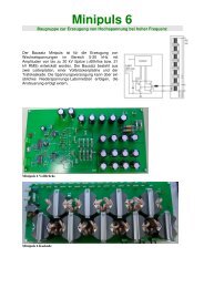
The <strong>pulse</strong> <strong>generator</strong> consists of 3<br />
<strong>pulse</strong> modules with paralelled<br />
outputs which are <strong>power</strong>ed<br />
separately.<br />
The <strong>pulse</strong> modules itself consists of a<br />
capacitor bank of 3mF and a semi full<br />
bridge for switching the output <strong>power</strong>.<br />
The modular design has the<br />
advantage of scaleability and<br />
partitions the energy storage, which<br />
is a safety advantage in case of<br />
failures.<br />
The device is fully protected against<br />
arcs and overloading.<br />
principal scheme of <strong>pulse</strong> module<br />
principal scheme <strong>RUP</strong>7
Technical Data <strong>RUP</strong>7 version3<br />
operation modes<br />
Standard <strong>pulse</strong><br />
Control signal (>8V) switches both transistors<br />
on and off, remaining inductive energy will be<br />
fed back to the capacitor bank through the<br />
diodes.<br />
An overcurrent event will also switch off both<br />
transistors and additionally inhibit <strong>pulse</strong> for 20<br />
ms.<br />
Switch mode supply mode<br />
Is active if control signal is between 2V and 8V.<br />
Similar as standard <strong>pulse</strong>, but the upper<br />
transistor is switched on and off with a<br />
frequency of 15 kHz and a duty cycle<br />
depending on control signal, increasing linear<br />
from 0% to 100% with voltage from 2V to 8V.<br />
The phase between the modules is shifted to<br />
get a more smooth current and voltage<br />
waveform.<br />
DC mode<br />
Both transistors are allways on; an overcurrent<br />
event will switch off both transistors and inhibit<br />
operation for 20 ms.<br />
Voltage and current<br />
• Output voltage 1000V max., adjustable.<br />
• Average output current 3A max.<br />
• peak current 360A positive (adjustable<br />
limit)<br />
• Output voltage is potential free, but any<br />
output should not be al<strong>low</strong>ed to deviate<br />
more than 1kV from ground.<br />
<strong>pulse</strong> shape and frequency<br />
• Intrinsic switching times are in the range<br />
0.1 - 0.5µs.<br />
• square wave, rise and fall time depending<br />
mainly on inductance. Internal inductance<br />
is around 33µH, corresponding to 100µH<br />
per module. So for a 2 Ohm load, the rise<br />
time constant may be around 33µs, wheras<br />
for a high <strong>impedance</strong> load (as non ignited<br />
plasma) the rise may be in the order of the<br />
intrinsic switching time, eventually with an<br />
overshoot of up to factor 2.<br />
• max. <strong>pulse</strong> with is limited by stored energy<br />
in the 9mF total capacitor bank. So a 360A,<br />
5ms <strong>pulse</strong> will cause a 200V voltage drop<br />
during <strong>pulse</strong>.<br />
• duty cycle may be varied from 0% to 100%.<br />
• Frequency: up to 15kHz, as long as<br />
internal switching losses do not exceed<br />
limits.<br />
means of control<br />
• 10-turn potentiometers for adjustment of<br />
• voltage (0-1000V)<br />
• current limit (0-360A)<br />
• Main <strong>power</strong> switch<br />
• buttons for high voltage on / off<br />
• switch for operation mode <strong>pulse</strong>/DC<br />
• LED for <strong>pulse</strong> generation on<br />
• LED for current threshold exeeded<br />
• meters for voltage and average current<br />
connectors<br />
• CE connector for mains supply<br />
• BNC for input control signal; 0-2V off, 2-8V<br />
switch mode supply mode, 8-10V <strong>pulse</strong><br />
mode<br />
• voltage monitor output 1:100<br />
• current output monitor 10mV/A<br />
• high current connectors for <strong>pulse</strong> output,<br />
3m output cable 10mm² included<br />
mechanical, environmental, included items<br />
• 19" rack 1400*600*800 mm<br />
• environmental temperature 5-35°C<br />
• humidity 0-80%, the <strong>pulse</strong> <strong>generator</strong> is<br />
intended for the use in dry rooms.<br />
• protection class I, IP20<br />
• supply voltage 230-240VAC 16A, 50-60Hz<br />
• manual, full schematics included<br />
safety<br />
• external interlock<br />
• outputs are potential free<br />
• The output and everything connected to it<br />
has dangerous voltages and must not be<br />
touched during operation.<br />
• The device contains large capacitors which<br />
may stay charged significant time after<br />
switching off. This has to be considered<br />
when handling the inside of the device.<br />
• The output currents must not be al<strong>low</strong>ed to<br />
f<strong>low</strong> through protective grounding systems<br />
otherwise severe disturbances may result.<br />
• This device is only for laboratory use by<br />
experts.<br />
company address<br />
GBS Elektronik GmbH<br />
Bautzener Landstr. 22<br />
01454 Großerkmannsdorf<br />
Tel.: ++49 351 217007-0<br />
Fax: ++49 351 217007-21<br />
Email: kontakt@gbs-elektronik.de<br />
http://www.gbs-elektronik.de<br />
Stand:19.3.2008