Mini MCA-166 User's Manual - GBS Elektronik GmbH
Mini MCA-166 User's Manual - GBS Elektronik GmbH
Mini MCA-166 User's Manual - GBS Elektronik GmbH

Create successful ePaper yourself
Turn your PDF publications into a flip-book with our unique Google optimized e-Paper software.
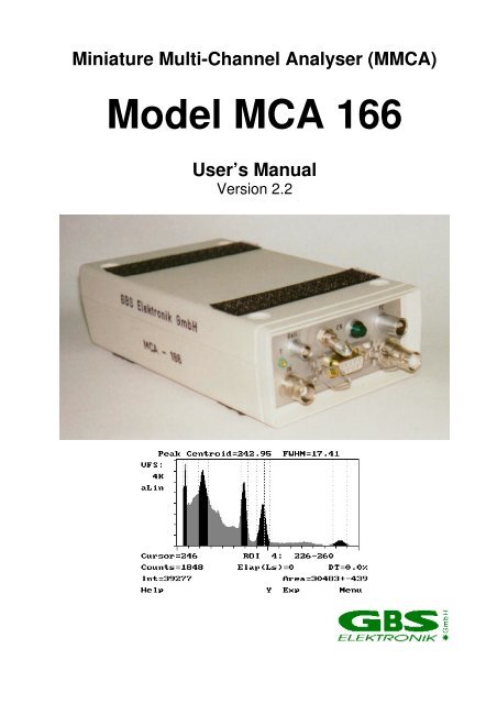
<strong>Mini</strong>ature Multi-Channel Analyser (M<strong>MCA</strong>)<br />
Model <strong>MCA</strong> <strong>166</strong><br />
User’s <strong>Manual</strong><br />
Version 2.2
Exclusion of liability<br />
_______________________________________________________________________<br />
The <strong>GBS</strong> <strong>Elektronik</strong> <strong>GmbH</strong> is not liable for errors and does not guarantee the specific<br />
utility of the <strong>MCA</strong> <strong>166</strong> software or firmware. In particular, the <strong>GBS</strong> <strong>Elektronik</strong> <strong>GmbH</strong> is not<br />
liable for indirect or subsequent damages due to errors of the <strong>MCA</strong> <strong>166</strong> software or<br />
firmware.<br />
The information in this manual has been carefully reviewed and is believed to be accurate<br />
and reliable. However, the <strong>GBS</strong> <strong>Elektronik</strong> <strong>GmbH</strong> assumes no liabilities for inaccuracies<br />
in this manual. This manual is subject to change without notice.<br />
Last update: 15.1.2001<br />
Address:<br />
<strong>GBS</strong>-<strong>Elektronik</strong> <strong>GmbH</strong><br />
Bautzner Landstraße 22<br />
01454 Großerkmannsdorf<br />
Tel.: (0351) 217007-0<br />
Fax: (0351) 217007-21<br />
For software updates or problems exceeding the frame of this manual refer to:<br />
Internet: http://www.gbs-elektronik.de<br />
or send email to: kontakt@gbs-elektronik.de<br />
2
_______________________________________________________________________<br />
Table of Contents<br />
1.0 Introduction<br />
1.1 <strong>Mini</strong> <strong>MCA</strong> (<strong>MCA</strong> <strong>166</strong>) Software Specification<br />
1.1.1 General Concept<br />
1.1.2 Basic Software Functions<br />
2.0 Hardware<br />
2.1 Users safety information<br />
2.1.1 Power source<br />
2.1.2 High Voltage supply<br />
2.2 General description<br />
2.2.1 Power management<br />
2.2.2 Switching on<br />
2.2.3 Connecting the <strong>MCA</strong><strong>166</strong> to the Charger<br />
2.2.4 Connecting the <strong>MCA</strong><strong>166</strong> to a Computer<br />
2.2.5 Connecting the Detectors<br />
2.2.6 Connecting the external additional battery pack<br />
2.2.7 Connecting the Power Pack<br />
3.0 Software<br />
3.1 System requirements, software installation and overview<br />
3.2 The DOS program <strong>MCA</strong> for operating the <strong>Mini</strong> <strong>MCA</strong><br />
3.2.1 File menu<br />
3.2.1.1 Open<br />
3.2.1.2 Save<br />
3.2.1.3 Exit<br />
3.2.2 Acquire menu<br />
3.2.2.1 Start<br />
3.2.2.2 Setup<br />
3.2.2.3 Clear<br />
3.2.2.4 Active group<br />
3.2.2.5 Mode<br />
3.2.3 Setup<br />
3.2.3.1 Detector High voltage setup<br />
3.2.3.2 Amplifier setup<br />
3.2.3.3 Stabilisation setup<br />
3.2.3.4 Preamplifier power setup<br />
3.2.3.5 Setup summary<br />
3.2.4 Analysis<br />
3.2.4.1 E-Calibration<br />
3.2.4.2 Smooth<br />
3.2.4.3 Strip<br />
3.2.4.4 Move<br />
3.2.5 Help<br />
3.2.5.1 Diagnostics<br />
3.3 The DOS program SPEC for measuring spectra<br />
3.3.1 File menu<br />
3.3.1.1 Open<br />
3.3.1.2 Save<br />
3.3.1.3 Autosave<br />
3.3.1.4 Exit<br />
3.3.2 Setup<br />
3.3.2.1 Read setup file<br />
3.3.2.2 Detector High voltage setup<br />
3.3.2.3 Presets<br />
3.3.2.4 <strong>MCA</strong> setup<br />
3.3.2.5 Amplifier setup<br />
3.3.2.6 Stabilisation setup<br />
3.3.2.7 Setup Summary<br />
3.3.3 Data acquisition menu<br />
3.3.3.1 Start<br />
3.3.3.2 Energy calibration<br />
3.3.4 Help<br />
3.3.4.1 Diagnostics<br />
3.4 The DOS program MCS for multi channel scaling<br />
3.4.1 File menu<br />
3.4.1.1 Open<br />
3
_______________________________________________________________________<br />
3.4.1.2 Save<br />
3.4.1.3 Autosave<br />
3.4.2 Setup<br />
3.4.2.1 Read setup file<br />
3.4.2.2 Detector High voltage setup<br />
3.4.2.3 MCS setup<br />
3.4.2.4 Amplifier setup<br />
3.4.2.5 <strong>MCA</strong> Setup<br />
3.4.2.6 Setup summary<br />
3.4.3 Data acquisition menu<br />
3.4.3.1 Measurement<br />
3.4.3.2 Smooth<br />
3.4.3.3 Energy calibration<br />
3.4.4 Help<br />
3.4.4.1 Diagnostics<br />
3.4.4.2 About<br />
3.5 Other DOS software<br />
3.5.1 U235<br />
3.5.2 UF6<br />
3.5.3 LENG<br />
3.5.4 RATE<br />
3.6 Windows software<br />
3.6.1 The program Win<strong>MCA</strong><br />
3.6.2 WinSPEC-I<br />
3.6.3 WinSPEC-A<br />
3.6.4 WinSCAN<br />
3.6.5 WinU235 and WinUF6<br />
3.6.6 Identify<br />
3.6.7 <strong>MCA</strong>Plot and <strong>MCA</strong>Print<br />
3.6.8 M<strong>MCA</strong>EVAL<br />
3.6.9 <strong>MCA</strong>WAND<br />
3.7 Other operating systems<br />
3.7.1 WinSpec CE<br />
3.7.2 SPEC for EPOC<br />
3.8 Example for Making a Measurement with a NaI-Detector<br />
3.9 Example for a Measurement with a CdZnTe Detector<br />
3.10 Example for a Measurement with a HPGe Detector<br />
3.11 Some examples for parameters of <strong>MCA</strong> used with different detectors<br />
3.12 Some of the most important photon energies<br />
4.0 Technical Data<br />
4.1 <strong>Mini</strong> <strong>MCA</strong> (<strong>MCA</strong> <strong>166</strong>) Hardware Specifications<br />
4.1.1 Amplifier<br />
4.1.2 ADC<br />
4.1.3 Power Supply<br />
4.1.4 Preamplifier Voltages<br />
4.1.5 High Voltage<br />
4.1.6 Battery<br />
4.1.7 Computer Interface<br />
4.1.8 Mechanical Specifications<br />
4.1.9 Environmental Ratings<br />
4.2 Block Diagram of the <strong>MCA</strong> <strong>166</strong> and wiring tables of the connectors<br />
5 Troubleshooting<br />
APPENDIX 1 <strong>MCA</strong> <strong>166</strong> spectral format<br />
APPENDIX 2 <strong>MCA</strong> <strong>166</strong> algorithm, formulas<br />
APPENDIX 3 Description of the <strong>MCA</strong> <strong>166</strong> Windows DLL command set<br />
APPENDIX 4 Description of the <strong>MCA</strong> <strong>166</strong> firmware functions<br />
APPENDIX 5 Changing the <strong>MCA</strong> <strong>166</strong> Firmware<br />
4
_______________________________________________________________________<br />
1.0 Introduction<br />
The <strong>Mini</strong> <strong>MCA</strong> (M<strong>MCA</strong>, model <strong>MCA</strong> <strong>166</strong>) is a battery powered high performance 4K Multi-<br />
Channel Analyzer/Multi-Channel Scaler module comparable in its performance with<br />
laboratory grade <strong>MCA</strong>s. High voltage supply for detector and preamplifier power supply<br />
are integrated as well as an internal amplifier and pulse shaping network. The <strong>MCA</strong> is<br />
optimized in its shape for use with a HP 200 Palmtop, but can also be used with any other<br />
Laptop or standard PC. Together with a small detector it forms a pocket-size gamma<br />
spectroscopy system and timer / counter, which is well suited to the demands of field<br />
measurements for international safeguards, environmental monitoring, nuclear waste<br />
treatment facilities, radioactive transport control and similar applications.<br />
Furthermore, the <strong>MCA</strong> <strong>166</strong> supports a vast number of different detectors and its 4k<br />
resolution is adequate to support high resolution gamma spectrometry with HPGe<br />
detectors.<br />
1.1 <strong>Mini</strong> <strong>MCA</strong> (<strong>MCA</strong> <strong>166</strong>) Software<br />
The <strong>Mini</strong> <strong>MCA</strong> software allows to operate the device as a general purpose multi channel<br />
analyzer (<strong>MCA</strong>, SPEC) and multi scaler analyzer (MCS). Additional user programs which<br />
support safeguards specific applications as U-235 enrichment verification (U235), spectral<br />
radiation survey meter mode supporting active length determination (LENG, UF6, RATE)<br />
are available. Since the lowest computer platform is the HP 100LX palmtop computer, the<br />
software works under MS-DOS (5.0 or higher) with the GUI (Graphical User Interface)<br />
optimized for the LCD screen of the HP200LX.<br />
For Win 95/98/NT, the programs WIN<strong>MCA</strong>, WINSPEC, WINSCAN, <strong>MCA</strong>PLOT,<br />
IDENTIFY and SFATWIN are available. More Windows programs are under<br />
development, the actual status can be found on the <strong>GBS</strong> homepage (http://www.gbselektronik.de/mca/software/index_e.htm).<br />
The device can also be operated with the<br />
ORTEC software (MAESTRO, GammaVision, ScintiVision etc.); contact ORTEC for<br />
details.<br />
The firmware of the <strong>MCA</strong> <strong>166</strong> (the software for the internal processor in the <strong>MCA</strong>) is<br />
described in Appendix 3 and 4. Instructions how to change firmware can be found in<br />
Appendix 5.<br />
1.1.1 General DOS software concept<br />
• to the extend possible setup menus provide MS Windows pull down menu’s and<br />
navigation "look and feel"<br />
• easy navigation is also present at the level of the HP 200LX<br />
• screens are easy to read on the HP 200LX palmtop computer LCD<br />
• special display to control and supervise the measurements<br />
1.1.2 Basic software functions<br />
• File menu: write/read functions with drive/path- and file picklist functions<br />
• Setup menu: ADC, Amplifier, Presets, Memory splitting, <strong>MCA</strong> mode, MCS mode, Multi<br />
spectral recording mode, automated instrument configuration using setup files<br />
• Acquire control: Start, Stop, Clear, Presets<br />
• Automated repeated measurement functions<br />
• Display functions: Automated linear and logarithmic, manual linear Y scale, X axis,<br />
expansion and scrolling, Cursor function, ROI setting and processing<br />
5
_______________________________________________________________________<br />
• Peak stabilization<br />
• Analysis functions: ROI peak area and integral, FWHM calculation<br />
• Analysis report function<br />
• Energy calibration function: linear calibration curve using 2 peaks<br />
• Incorporated Help texts<br />
• Print screen for quick documentation<br />
6
_______________________________________________________________________<br />
2.0 Hardware<br />
2.1 Users safety information<br />
Read all these instructions first.<br />
Save these instructions for later use.<br />
Do Not Remove Connectors<br />
To avoid personal injury or damage of equipment, do not remove the connectors<br />
for the High Voltage supply, preamplifier supply, and the input connector until the High<br />
Voltage is shut down and the device is switched off at least for 1 minute.<br />
Do Not Remove Covers<br />
Do not open the device before the power is switched off.<br />
2.1.1 Power Source<br />
This device is intended to operate from an internal accumulator set (high<br />
performance Li-Ion battery) or together with the external charger from a power<br />
source.<br />
Do not apply more than 240 volts rms between the supply conductors of the charger.<br />
The power cord and the connector must be in a good condition.<br />
Do not allow anything to rest on the power cord.<br />
2.1.2 High Voltage Supply<br />
Make sure that the High Voltage connector and the High Voltage supply cable<br />
of the detector are in a good condition before connecting them to the <strong>MCA</strong> <strong>166</strong><br />
or before switching the High Voltage on.<br />
Do not allow anything to rest on the HV cable.<br />
Never insert objects of any kind into the High Voltage connector as they may touch the<br />
dangerous voltage point. This might cause an electric shock or a damage of the device.<br />
2.2 General Description<br />
The <strong>MCA</strong> <strong>166</strong> is an autonomous module. The device has its own battery and provides<br />
power supply to radiation detectors. Together with a computer the <strong>MCA</strong> <strong>166</strong> forms a multi<br />
channel analyzer. The spectra are collected in the memory of the <strong>MCA</strong> <strong>166</strong> and are<br />
transferred via a serial interface periodically to the computer. The computer is used to<br />
setup the <strong>MCA</strong> <strong>166</strong>, to display and process the measurement results, and to store the<br />
data. The design concept of the <strong>MCA</strong> <strong>166</strong> also supports a Multi-Channel Scaler mode.<br />
For operation the <strong>MCA</strong> <strong>166</strong> itself has only a power switch and a green LED indicator.<br />
2.2.1 Power management<br />
The <strong>MCA</strong> <strong>166</strong> works with a built in re-chargeable Li-Ion battery, which has no memory<br />
effect and is deep discharge and short circuit protected. If the device is working, the<br />
remaining battery life time is permanently checked. When the battery voltage has dropped<br />
down to 6.8 Volts, while a data collection is in progress, the <strong>MCA</strong> <strong>166</strong> gives out a warning<br />
to the user (the lamp will flash irregularly and the software will show an error message).<br />
The running measurement is automatically stopped and the detector high voltage<br />
together with the preamplifier power supply will be switched off.<br />
The user can now transfer the measured spectrum to the computer, but should switch the<br />
device off afterwards or connect the charger. If the user does not respond, and the<br />
battery life time is nearly used up (battery voltage 6.5 Volts) , the device switches off<br />
7
_______________________________________________________________________<br />
automatically. It is made sure, that the set up and the spectrum previously gathered is<br />
saved in the memory of the <strong>MCA</strong> <strong>166</strong> for at least several month.<br />
The remaining battery life time is sufficient to transfer the measured spectrum to a<br />
computer. It is recommended, before reading out the <strong>MCA</strong> <strong>166</strong>, to connect it to the<br />
charger.<br />
In the case that the battery voltage drops below its lowest value, the battery itself switches<br />
off. This can be, for example, the result of a lasting short circuit at the preamplifier power<br />
supply. As a consequence the internal setup and the measured values are lost. The<br />
<strong>MCA</strong> <strong>166</strong> has to be connected to the charger to recharge the battery.<br />
2.2.2 Switching on<br />
The <strong>MCA</strong> <strong>166</strong> is set into operation by turning the power switch on (see Fig. 1 for it’s<br />
location). After a waiting time of a few seconds for the internal reset and check up, the<br />
green power ON LED flashes with a frequency of 2.5 Hz if no M<strong>MCA</strong> software runs on the<br />
connected computer. If the power switch is already in position ON (for example after an<br />
automatic switch off due to a complete loss of battery power) switch OFF and to ON<br />
again. When the power ON LED does not flash, connect the <strong>MCA</strong> <strong>166</strong> with the charger<br />
and repeat once more. The <strong>MCA</strong><strong>166</strong> is online with the computer if the LED flashes with<br />
1.2 Hz. Irregular flashing of the lamp indicates an error.<br />
Figure 1 Front Panel of <strong>MCA</strong> <strong>166</strong><br />
2.2.3 Connecting the <strong>MCA</strong> <strong>166</strong> to the Charger<br />
Before connecting the charger to the <strong>MCA</strong> <strong>166</strong> pull out the mains power connector of the<br />
charger! Otherwise the charger does not work properly.<br />
In one version of the charger, make sure that the switch is in the “charge” position.<br />
First connect the Lemo (see Table 1 in chapter 4.2 for a wiring diagram) to the <strong>MCA</strong><strong>166</strong>.<br />
Then plug the power connector (see Fig. 12 in chapter 4.2 for a block diagram) into the<br />
power socket. The CHARGE lamp (orange) of the charger will light and charging will<br />
begin. When the charging is completed, the CHARGE lamp will switch off.<br />
If the CHARGE lamp flashes permanently, check the connection to the <strong>MCA</strong> <strong>166</strong>, and<br />
disconnect and connect the power connector to the power socket again.<br />
It is possible to work with the charger permanently connected to the <strong>MCA</strong> <strong>166</strong>.<br />
2.2.4 Connecting the <strong>MCA</strong><strong>166</strong> to a Computer<br />
The <strong>MCA</strong><strong>166</strong> is interfaced to the serial port (Table 2) with a fixed baudrate of 38.4 kBaud.<br />
The baudrate on the computer is set automatically by the M<strong>MCA</strong> software. The special<br />
short serial interface cable is used to connect the HP 200LX proprietary connector to the<br />
8
_______________________________________________________________________<br />
serial interface Lemo connector, type 0S-303 of <strong>MCA</strong> <strong>166</strong>. To<br />
connect the <strong>MCA</strong> <strong>166</strong> with a notebook PC or any other industry standard PC, the<br />
interface cable with the standard D9 connector of the computer will be used.<br />
For use with the HP680 request a special cable.<br />
For proper wiring see 4.2.<br />
2.2.5 Connection of detectors<br />
To connect a detector switch the device off.<br />
Before connecting the high voltage connector of the detector:<br />
Make sure that the built in High Voltage supply has the right polarity and that the power<br />
consumption of the detector does not exceed the maximum value ( 0.5 mA or 0.25<br />
Watt).<br />
Polarity can be checked by Software; go to the menu setup-high voltage and look at<br />
indicated polarity. You can also open the <strong>MCA</strong> and check the HV module itself (red HV<br />
module - positive, blue HV module - negative). The correct values for HV, polarity, and<br />
power consumption should be found in the detectors manual.<br />
• Check by the detector manual that the pin assignment of the preamplifier power supply<br />
connector is compatible with the <strong>MCA</strong> <strong>166</strong>, and that the power consumption does not<br />
exceed the maximum ratings (see Table 3, Chapter 4.2).<br />
• Connect the cable for the preamplifier power supply of the detector to the concerning<br />
female D9 connector on the <strong>MCA</strong> <strong>166</strong> and attach it by the clamps.<br />
• Plug the BNC Signal connector of the detector to the female BNC input connector of<br />
<strong>MCA</strong> <strong>166</strong>.<br />
• Plug the High Voltage connector of detector into the female SHV connector of<br />
<strong>MCA</strong> <strong>166</strong>.<br />
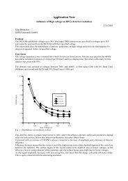
If problems occur it is possible to check the detector signal and the main amplifier signal<br />
(Amplifier Test out, see figure 1) with a scope. A typical signal which should be seen is<br />
shown in figure 2.<br />
Detector Signal (V)<br />
Amplifier (V)<br />
0<br />
-0.01<br />
-0.02<br />
-0.03<br />
-0.04<br />
1<br />
0<br />
0 5 10 15<br />
Time (µs)<br />
Figure 2: Typical signals which can be seen at the detector preamplifier out and the<br />
amplifier test out. This example: CdZnTe Detector SDP310/Z/60, measuring a Cs137<br />
9
_______________________________________________________________________<br />
sample, amplifier setting 200*0.91, negative pulses, 1µs shaping time, pulse height<br />
equals to about channel 662 of 1024 channels.<br />
Typical errors which may be observed with the detector preamp signal are:<br />
-Rise time is too slow (>0.5 µs). This may cause the pile up rejector not to work correctly.<br />
There may be even a large amount of regular pulses rejected and especially the high<br />
energetic part of the spectrum seriously affected. When using such detectors switch pile<br />
up rejection off.<br />
-The fall time is too fast (time constant resp. 1/e fall time < 40µs). This causes that the<br />
pole/zero setting cannot be correctly adjusted. Consequences may be peak shift and<br />
peak broadening with higher countrates and increased low energy spectrum cutoff. Try to<br />
used another preamplifier.<br />
2.2.6 Connecting the external additional battery pack<br />
The additional battery pack can be used to extend measuring time up to 250% of that of<br />
the stand-alone <strong>MCA</strong> (e.g. to 20 hours with a HPGe detector and to about 35 hours with a<br />
NaI or CdZnTe detector. The “<strong>MCA</strong>” cable has to be plugged into the “Batt.” connector of<br />
the <strong>MCA</strong>. By the electronics in the battery pack, charge exchange current between the<br />
batteries is limited to 1A and reverse current (if an empty battery pack is connected to the<br />
<strong>MCA</strong>) is inhibited. The current from the battery pack can be seen in the diagnostics menu<br />
as “charger current”. The amount of current from the battery pack depends on voltage<br />
differences between the batteries and the impedance off the <strong>MCA</strong> battery (about 1 Ohm).<br />
If there is no current from the battery pack (or only something like 2 mA) then the voltage<br />
of the battery pack is lower than voltage of the <strong>MCA</strong> battery. It should also be noted that<br />
in the diagnostic menu only the amount and not the sign of a charging current is<br />
registered. So a power consumer (e.g. a resistor) placed willfully at the “Batt.” connector<br />
may be not distinguished from a power source.<br />
The battery pack can be connected to a charger via the “Batt.” connector.<br />
For even longer measurement times, infinite numbers of battery packs can be connected<br />
in chain.<br />
Battery Charge state (%)<br />
100<br />
80<br />
60<br />
40<br />
20<br />
0<br />
6 7 8<br />
Battery Voltage (V)<br />
Fig. 3: Charge state of the <strong>MCA</strong> battery in dependence of the battery voltage.<br />
The charge state off the additional battery pack alone can be evaluated by measuring its<br />
voltage at the “Batt.” connector. This is practically best done by plugging in the cable to<br />
the charger with the connecting block on the charger side removed. Then the voltage can<br />
be measured easily with a multimeter at the plug inserts of the connecting block.<br />
10
_______________________________________________________________________<br />
2.2.6 Connecting the Power Pack<br />
The powerpack is an extension of the akkupack with an high performance integrated<br />
power supply. Standard detector preamplifier voltages as well as an extra 5V supply are<br />
delivered.<br />
The Powerpack may be used to manage also power-hungry detectors or detectors with a<br />
5V demand.<br />
It may be used it as backup battery for the <strong>MCA</strong><strong>166</strong> similar as the akkupack.<br />
Or use just as a stand-alone versatile power supply for many nuclear electronics.<br />
11
_______________________________________________________________________<br />
Specifications:<br />
All outputs are short circuit proof. Overloading of any output leads to shutdown of all<br />
output supply voltages (except the <strong>MCA</strong> Batt output)<br />
Ripple on all regulated outputs:
_______________________________________________________________________<br />
3.0 Software<br />
3.1 System Requirements, Software Installation and Overview<br />
<strong>Mini</strong>mal system and software requirements for MS-DOS based user programs:<br />
• PC - XT compatible computer<br />
• CGA compatible display adapter<br />
• 640 KB conventional RAM (550 KB free lower DOS memory)<br />
• 1 MB disk space<br />
• COM 1 port (16550 compatible UART recommended)<br />
• MS-DOS V5.0 or higher<br />
For PCs running Windows 3.xx it is strongly recommended to start the <strong>MCA</strong> software in<br />
MS-DOS mode to prevent problems in serial communication. See also chapter 5,<br />
troubleshooting.<br />
<strong>Mini</strong>mal system requirements for the Windows based user programs:<br />
Any PC able to run Windows 95/98<br />
COM port<br />
VGA Screen<br />
Windows 95/98/NT<br />
Some programs (<strong>MCA</strong>Plot, Identify) are also available in Windows 3.1 version<br />
The <strong>MCA</strong> DOS-software usually consists of the following 3 files:<br />
• the executable file (e.g. mca.exe)<br />
• the screen file (e.g. mca.lnf)<br />
• the help file (e.g. mca.hlp)<br />
To install the <strong>MCA</strong> software from the MS-DOS prompt:<br />
• Insert the <strong>MCA</strong> <strong>166</strong> distribution disk in drive A:<br />
• Type A: and press ENTER<br />
• Type XCOPY A:\ C:\ /S and press ENTER.<br />
The programs must always be started from their directory in order to run correctly. After<br />
starting the program it will try to detect the default data directory and creates one in the<br />
root of the actual drive (e.g. c:\data).<br />
On the HP200LX, the software is preinstalled on the flashdisk a:\ .<br />
All programs are called from the Main Menu, which appears automatically when the<br />
computer has booted or re-booted (for the HP 200LX from drive a:). Before you start<br />
measurements check or reset date and time on the computer and check its battery status.<br />
If the HP main battery level is < 2.4 V and the backup battery level is < 2.7 V, replace it.<br />
At the DOS prompt, use the "dir a:" command to make sure that you have enough storage<br />
space on drive a: (or c: if a notebook computer is used).<br />
Use the Norton Commander to delete old files if there is less than 1 Mb free space.<br />
CTRL-ALT-DEL resets the computer and brings up the Menu again. CTRL-ALT-ON does<br />
a hard reset of the HP 200LX computer and brings also up the menu again. All programs<br />
13
_______________________________________________________________________<br />
can also be used offline for data viewing and evaluation without a M<strong>MCA</strong> module<br />
connected.<br />
The <strong>MCA</strong> software will fully use all the hardware and firmware features of the <strong>MCA</strong>. This<br />
includes setup, measurement control, data display and analysis, storage and retrieval of<br />
data. In the <strong>MCA</strong> emulation software only data evaluation features are implemented. For<br />
more advanced processing the data can be read in other software packages.<br />
The program "<strong>MCA</strong>" was the first emulation program for the <strong>MCA</strong>, all other programs are<br />
derived from it. This program is mainly used for testing and general applications.<br />
For measuring spectra, the program "SPEC" is more recommended.<br />
The program "MCS" allows to measure time-dependent count rates; there is also a mode<br />
where amplitude and time spectra can be recorded simultaneously.<br />
There exist also further programs for special applications at IAEA, such as U235, UF6,<br />
RATE, LENG. These programs are not described here in short form only.<br />
Note that the <strong>MCA</strong> emulation software is DOS based, written and optimized for the HP<br />
Palmtop hardware (i80x86 CPU, CGA/VGA video adapter, monochrome display and<br />
special keyboard layout). Some features are therefore not optimum for desktop or laptop<br />
computers.<br />
If you want a more convenient working with a desktop, WIN<strong>MCA</strong> or WINSPEC are<br />
recommended.<br />
For creating own software for the <strong>MCA</strong>, the <strong>MCA</strong> command set is described in appendix 3<br />
and 4.<br />
For the newest software versions, refer to the <strong>GBS</strong> homepage<br />
http://www.gbs-elektronik.de/mca/software/index_e.htm and ask for updates.<br />
3.2 The DOS program <strong>MCA</strong> for operating the <strong>Mini</strong> <strong>MCA</strong><br />
The emulation software has one startup screen and three different screens - one<br />
character based menu screen and two almost similar graphical screens showing the<br />
spectra. This variety of screens might seem to be confusing, but has advantages. The<br />
screens are clearly separated according to their functions.<br />
The start up screen (Fig. 4) shows general information about the software, the attached<br />
<strong>Mini</strong> <strong>MCA</strong> and its state of operation. Here you are asked whether you want to reset the<br />
<strong>MCA</strong>. It also complains if <strong>MCA</strong> power is off or no <strong>MCA</strong> is connected, but you can use the<br />
software also offline. If you start the <strong>MCA</strong> program offline, the "start" command is<br />
disabled, and in all the setup menus changes are possible but will have no effect.<br />
<strong>MCA</strong> Emulation Program<br />
Copyright (C) 1997<br />
Forschungszentrum Rossendorf e. V.<br />
Software Version: 1.61<br />
<strong>Mini</strong> <strong>MCA</strong> Number: 129<br />
Hardware Release: 9701<br />
Firmware Release: 9801<br />
Reset M<strong>MCA</strong> to default setup<br />
and clear all spectra (y/n)?<br />
14
_______________________________________________________________________<br />
Figure 4. Startup Screen<br />
The MENU screen (Fig. 5) with the main menu bar and the sub-menus is mainly used for<br />
instrument setup and control.<br />
File Acquire Setup aNalysis Help<br />
<strong>MCA</strong> <strong>166</strong> online HV: Off Group:1<br />
Figure 5. Menu Screen<br />
General Navigating through this program:<br />
• Use the arrow keys to move the cursor around<br />
• Use the enter key to enter a menu or to confirm an action<br />
• Use the space key to toggle between settings<br />
• Use the ESC key to exit a menu, you are then asked if you want to accept the<br />
settings; (this does not comply with Windows GUI standards but was caused by the<br />
DOS GUI development tool used to develop the software)<br />
3.2.1 File menu<br />
The file menu allows to open and to save files. Files are spectral data files with setup<br />
information.<br />
3.2.1.1 Open<br />
Here you reach a submenu with the choices to open a drive and file selection box or to<br />
set file retrieve options.<br />
Another "Open" leads to a file selection box. Under "Dir", you can type the drive letter, for<br />
e.g., "a:\". In the right part of the box, the roots directory and subdirectories of the drive<br />
are shown. Move the cursor bar to the desired subdirectory and press Enter to select it.<br />
Pick the file in the left box with the cursor bar and press Enter to retrieve it.<br />
"Options" leads to a menu to set the options for retrieving a file. Normally, all options are<br />
set to "yes" to retrieve a file with all setup, ROI and calibration information. If, for e.g., only<br />
the ROI option would be set to "yes", only the ROI list would be retrieved and could be<br />
15
_______________________________________________________________________<br />
overlayed to a spectrum already stored in the memory. Use the spacebar to toggle the<br />
options between "yes" and "no".<br />
3.2.1.2 Save<br />
Here you reach a submenu offering the choice to open a drive box or to set file save<br />
options.<br />
With "Save" you enter a drive and file box. Under Dir, you can type the drive letter, e.g.,<br />
a:\ and press Enter. Using the Arrow and Enter keys, select the subdirectory into which<br />
the file is to be saved. Type the filename under File. Move the cursor bar to OK and press<br />
Enter to save the file.<br />
With "Option" you reach an options setting menu for saving a file. Normally all options are<br />
set to "yes" to save a file with all setup, ROI and calibration information. If, for e.g., only<br />
the ROI option would be set to "yes", then only the ROI list would be saved. Use the<br />
spacebar to toggle the options between "yes" and "no".<br />
3.2.1.3 Exit<br />
Leaves the <strong>MCA</strong> emulation program and exits to the DOS prompt. The <strong>MCA</strong> module,<br />
however, may continue to collect a spectrum. So you can disconnect the computer and<br />
leave the <strong>MCA</strong> measuring on its own. But, if you want to do this, leave the high voltage on<br />
when exiting, and, after connecting the <strong>MCA</strong> again and starting the <strong>MCA</strong> program, do not<br />
reset the <strong>MCA</strong>, otherwise the measurement will be deleted.<br />
3.2.2 Acquire menu<br />
The acquire menu provides a start function to begin data collection. The data gathering is<br />
controlled from the graphic screen. It further provides acquire presets and <strong>MCA</strong> or MCS<br />
mode selection including their setup. One of the three memory groups of the <strong>MCA</strong> can be<br />
chosen as an active group for data collection. A clear function allows to clear all ROIs and<br />
data.<br />
3.2.2.1 Start<br />
The first graphic screen is the ACQUIRE screen, which contains operative information like<br />
count rate, presets for the measurement and which provides a quickly updated live<br />
display of the spectrum. To start a measurement, press F4. During a measurement only<br />
256 channels (the width of the spectral display) are transferred automatically every 2 sec.<br />
from the <strong>Mini</strong> <strong>MCA</strong> to the (Palmtop-) PC.<br />
16
_______________________________________________________________________<br />
Figure 6. Aquire Screen that will appear after selecting START from the Acquire menu<br />
If an intermediate evaluation is needed, a full spectrum (snap shot, no life spectrum<br />
display; not updated unless requested by pressing F2 again) is presented on a second<br />
graphical screen (EVALUATION screen) showing the evaluation information (peak<br />
information, numeric calculations, ...) To enter the evaluation screen, press F2.<br />
Figure 7 Evaluation Screen.<br />
A cursor (bold dotted line) is available on both screens and ROIs are indicated (intense<br />
regions in between two dotted lines).<br />
• To move the cursor, use right and left arrow key<br />
• To mark a ROI, press the SHIFT key while moving the cursor and release SHIFT<br />
and then the arrow key after the end of the ROI has been reached.<br />
• To delete a ROI, move the cursor into the ROI and press the DELETE key.<br />
Both screens have the same principal layout. The top line shows the path and filename<br />
of the spectrum. On the left side the vertical full scale (VFS) is displayed together with the<br />
Y scale mode (either automated linear, logarithmic or manual linear), change this with F6.<br />
In addition, the ACQUIRE screen shows the remaining battery capacity of the <strong>MCA</strong>.<br />
Under the spectra display, there are four lines with status information, some of them<br />
appearing on both the ACQUIRE and EVALUATION screens (e.g. the cursor information,<br />
ROI- resp. X-range and the dead time). If the cursor is within a ROI, its number and<br />
boundaries are shown. On the EVALUATION screen is then additionally the peak<br />
17
_______________________________________________________________________<br />
information (integral, area, centroid and FWHM) shown. If the <strong>MCA</strong> is calibrated, peak<br />
information is shown in keV, otherwise in channels.<br />
The last row of the graphics screens shows the actual functions of the function keys.<br />
(From left -F1- to right -F10- ; on the HP200LX the corresponding function keys are just<br />
below the screen).<br />
3.2.2.2 Setup<br />
Allows to setup the acquire functions like Presets, <strong>MCA</strong> channels, Threshold, Upper and<br />
lower Level discriminators (LLD, ULD), ADC input and automated repetitive<br />
measurements. The parameters asked for depend on if the <strong>MCA</strong> is set to <strong>MCA</strong> or MCS<br />
mode.<br />
Stop condition (Only in <strong>MCA</strong> mode)<br />
Allows to set the preset choices. Possible are: Real time (just the elapsed time, sec.), live<br />
time (the elapsed time subtracted by the <strong>MCA</strong> dead time, in sec., default), Integral, Peak<br />
Area (peak integral subtracted by background, see appendix 2 for the formula) and infinite<br />
measurement. For integral and peak area a ROI must be set. Use the space bar to toggle<br />
between the choices.<br />
Value (only <strong>MCA</strong> mode)<br />
Use this field to input a preset value - this can either be set as the number of seconds or<br />
the number of counts. The maximum number of preset seconds is 65536, the maximum<br />
number of preset counts is 10.000.000 . Default is 300s or counts.<br />
ROI (only <strong>MCA</strong> mode)<br />
Allows to select one of the ROIs which is used as preset for the integral counts or the<br />
peak area in that ROI.<br />
Channels (<strong>MCA</strong> mode)<br />
Allows to set the number of <strong>MCA</strong> channels. Use the space bar to toggle between<br />
128....4096 channels. Note that the last 128 channels of 4096 can not be used and<br />
remain empty (and correspondingly the last 64 of 2048, etc.). Default is 4096 channels.<br />
For a HPGe detector, the choice will be in most cases 4096 channels, whereas for a<br />
CdZnTe detector 1024 channels are enough. For a NaI 256 channels are sufficient.<br />
Channels (MCS mode)<br />
Use the spacebar to select between 128...4096 MCS channels. Default is 4096 channels.<br />
Time per Channel (only MCS mode)<br />
Enter the time per channel in increments of 10 msec.<br />
Threshold<br />
Allows to set a threshold value between 2% and 60% of the current <strong>MCA</strong> scale. Default is<br />
2%. This analogue threshold cuts the pulses before they reach the ADC. Setting the<br />
threshold high discriminates unwanted pulses and reduces the dead time of the ADC.<br />
Do visual threshold adjustment<br />
Allows to adjust the threshold using visual control of the spectrum.<br />
18
_______________________________________________________________________<br />
LLD, ULD<br />
LLD allows to set the lower level discriminator of the ADC. All channels below the LLD<br />
value remain empty. The ADC deadtime, however, is not reduced. The value for LLD<br />
must be < ULD. Default is 0.<br />
ULD allows to set the upper level discriminator (ULD) of the ADC. All channels above the<br />
ULD value remain empty. The ADC deadtime is not reduced. The value for ULD must be<br />
> LLD. Default is highest possible channel.<br />
In MCS mode (main application for this), if LLD/ULD is set, LLD and ULD define the limits<br />
within impulses are counted.<br />
In <strong>MCA</strong> mode, it is more recommended to use Threshold than LLD to remove noise and<br />
low energy components of the spectrum.<br />
ADC input (<strong>MCA</strong> mode)<br />
Use the spacebar to toggle between the 2 different direct inputs ("+ 3V dir.", "-3 V dir.") if<br />
you want to use, for e.g., an external amplifier, or select "Amplifier" in order to use the<br />
internal amplifier. Default is amplifier.<br />
Input Type (MCS mode)<br />
Use the spacebar to select between "extern TTL" (pulses), "Input Rate" (from the M<strong>MCA</strong><br />
count rate meter) or LLD/ULD (Only impulses between the LLD/ULD limit are counted).<br />
Default is TTL. This provides the highest countrate capability up to 10 6 cps.<br />
Repeat (<strong>MCA</strong> mode)<br />
Allows automated data collection and saving of spectra. After the preset is reached, the<br />
spectrum is automatically recorded into a pre-selected subdirectory and then the next<br />
measurement is started. At first a file with a filename using the scheme XXX00000.spe (3<br />
letters and 5 digits) must be saved. XXX is user selected to distinguish between<br />
measurement series kept in the same subdirectory. File name and directory are set under<br />
File Save. Up to 65535 files can be automatically recorded. Default is 0 (no repetitive<br />
measurements).<br />
Sweeps (MCS mode)<br />
Allows automated repetitive MCS spectra collection like Repeat in <strong>MCA</strong> mode.<br />
3.2.2.3 Clear<br />
Allows to clear all ROIs and all data in either the active or all memory groups. Clear ROIs:<br />
Use the spacebar to select the right choice. Note: Set data option to "no", if only ROIs<br />
should be cleared! Clear Data: Use the spacebar to toggle between "all" and "active<br />
group" depending on which data should be deleted.<br />
3.2.2.4 Active group<br />
Allows to set one of 3 memory groups into which a spectrum is collected. The first group<br />
is selected by default. Use the spacebar to toggle between active group 1, 2 and 3.<br />
There are still some bugs within this function.<br />
3.2.2.5 Mode<br />
You can set the acquisition mode here either to <strong>MCA</strong> or to MCS mode. <strong>MCA</strong> mode<br />
measures pulse height spectra which corresponds almost always to measure energy<br />
spectra. MCS measures time dependent count rates. All channels correspond to an<br />
equidistant sequence of time windows, the number of counts in the time window is stored<br />
19
_______________________________________________________________________<br />
in the corresponding channel. Parameters can be adjusted in the acquisition-setup menu.<br />
A possible application for MCS mode are decay time measurements or unattended<br />
monitoring measurements.<br />
3.2.3 Setup<br />
The setup menu provides hardware setup functions related to the amplifier and<br />
detector/preamplifier power supply. The default values for different settings are:<br />
Parameter default<br />
High voltage 0<br />
Coarse gain 100<br />
Fine gain 1.0000<br />
Shaping time 1<br />
Input polarity pos<br />
Pile up rejector on<br />
PZC 1600 mV<br />
3.2.3.1 Detector High voltage setup<br />
Allows to set the value for the high voltage which is used by the detector. Input the value<br />
for the detector high voltage here. The polarity is automatically set through the hardware,<br />
depending on what bias module is plugged in. The high voltage is turned on after this<br />
dialogue box is left with ESC and the corresponding message to turn the high voltage on<br />
is acknowledged. The status of the high voltage is shown on the status bar at the lowest<br />
line of the screen.<br />
The voltage as well as the polarity necessary is normally indicated on the detector or at<br />
least in the detector's manual. Do not exceed the maximum voltage for the detector! Use<br />
the right polarity! Using lower voltages is possible, in the case of HPGe detectors the<br />
resolution will degrade a bit using lower voltages. For a NaI-detector with a<br />
photomultiplier, the amplification will change with high voltage.<br />
3.2.3.2 Amplifier setup<br />
This submenu can only be activated if ADC input (see 3.2.2.2) is set to Amplifier<br />
Allows to setup the amplifier parameters like gain, shaping time, input polarity, pile up<br />
rejector (PUR) and pole zero cancellation (PZC). PZC and gain can also be adjusted<br />
using a graphic screen to support fine tuning.<br />
Coarse gain<br />
Use space bar to select the value for the coarse gain (2-1000).<br />
Fine Gain<br />
Input the value for the fine gain (0.5000 - 1.5000).<br />
Do visual gain adjustment<br />
Press Enter to switch to a graphical screen with the spectrum. Use the screen to adjust<br />
the fine gain while observing the spectrum. If the cursor is currently in a ROI then the<br />
peak centroid will be shown. This is useful to do some coarse calibration by adjusting fine<br />
gain in a way that an even proportion between channel numbers and photon energy is<br />
achieved.<br />
20
_______________________________________________________________________<br />
Shaping time<br />
Use the space bar to toggle between the two time constants 1 and 2 microseconds. The<br />
shaping time is the time constant of the RC in the pulse shaping network. The pulse<br />
FWHM time is about 3.5 times the shaping time, the total pulse time (from 1% peak<br />
amplitude to 1% peak amplitude) may be as long as 10 times the shaping time. Use 2<br />
microsec for low countrate measurements with a HPGe detector where the best<br />
resolution is needed and 1 microsec in all other cases.<br />
Polarity<br />
Use the spacebar to toggle between amplifier input pulses with negative or positive input<br />
polarity. Remember: Wrong polarity is a common reason for measuring strange spectra or<br />
getting no signal at all.<br />
PUR<br />
Use the spacebar to turn the pile up rejector (PUR) "on" or "off". The pile up rejector<br />
should cancel pulses which are very close together in time in order to avoid registering<br />
them as one pulse with the energy summed. The corresponding dead time is accounted<br />
for by the dead time correction scheme.<br />
Do visual PZC adjustment<br />
Press Enter to access the graphical screen which visualizes the pole zero adjustment. For<br />
adjusting PZC a count rate of 1000 - 10000 should be optimum, (300 - 30000 may still<br />
work) and the majority of these pulses should fill the measurement range at least to the<br />
half. The bar indicates the difference between the voltage at the ADC 11 µs after the<br />
pulse peak (22 µs for 2 µs shaping time) and 100 µs after the pulse peak. This voltage<br />
should be adjusted to zero. A wrong PZC setting may lead to a degraded resolution, in<br />
particular at high countrates.<br />
It is also possible to observe the amplifier signal at the amplifier test output with a scope<br />
using a high impedance, low capacitance probe and to adjust PZC.<br />
3.2.3.3 Stabilization setup<br />
This function is mostly useful for scintillation detectors as NaI. The pulse amplitude of<br />
these detectors depends not only on photon energy, but is also sensitive to<br />
photomultiplier voltage and crystal temperature. This drift can be compensated by<br />
regulating the fine gain of the amplifier to keep the position of a reference peak. The<br />
reference peak has to be marked as a ROI. Usual is to use the alpha peak of an Am241 -<br />
source. Some detectors have for this purpose a built-in Am241 source. In enrichment<br />
measurements, it is also possible to stabilize on the 186 keV peak of U235.<br />
To activate stabilization, turn on stabilization by toggling the stabilization on/off setting<br />
with the spacebar. You are then asked to accept or to change the stabilization ROI<br />
settings.<br />
3.2.3.4 Preamplifier power setup<br />
Allows to turn certain preamplifier supply voltages off to extend battery life by about 10%.<br />
Use the spacebar to turn a preamplifier supply voltage off in case the used preamplifier<br />
21
_______________________________________________________________________<br />
does not use a certain voltage. If supply voltages which are not needed are turned off, the<br />
battery lasts longer !<br />
3.2.3.5 Setup Summary<br />
This feature provides an overview on the setup parameters. It does not allow any editing<br />
and is meant to give an overview on the current setup parameters.<br />
3.2.4 Analysis<br />
The analysis menu allows to perform basic <strong>MCA</strong> analysis functions like energy calibration,<br />
the movement of a spectrum from one memory group to another, smoothing of a<br />
spectrum, and subtraction of spectra.<br />
3.2.4.1 E-Calibration<br />
Allows to perform a two point energy calibration. The calibration coefficients can be set as<br />
numeric values (channel energy pairs), as cursor position, or as peak centroid using the<br />
graphic screen.<br />
E-Calibration<br />
Use the spacebar to turn the energy calibration "on" or "off".<br />
Peak-Position<br />
Use the space bar to switch between the use of the peak centroid, the cursor position to<br />
determine the peak location, or manual input of coefficients.<br />
Do calibration now<br />
Switches to a graphic screen to do the energy calibration.<br />
Input Channel 1<br />
Enter lower channel number (in manual mode only) and corresponding energy<br />
Input Channel 2<br />
Enter upper channel number (in manual mode only) and corresponding energy<br />
Input Coefficients (manual mode only)<br />
Enter the slope in keV/channel and the offset in keV.<br />
3.2.4.2 Smooth<br />
Allows to smooth a spectrum. The smoothed spectrum overwrites the original spectrum.<br />
Use the space bar to switch between a 3 or 5 point smoothing.<br />
3.2.4.3 Strip<br />
Allows to subtract or add two spectra which must be stored in two groups of the M<strong>MCA</strong><br />
memory. The resulting spectrum overwrites the spectrum in the first group. Sign of<br />
stripping factor: A positive sign (default) leads to the subtraction of the spectrum stored in<br />
the background group, a negative sign adds the spectrum.<br />
You can input a stripping factor (default: 1). The spectrum stored in the background group<br />
will be multiplied with this factor before it is subtracted (or added) to the spectrum stored<br />
22
_______________________________________________________________________<br />
in the sample group. Use the spacebar to select the number of the<br />
memory group where the sample spectrum is stored and where the background spectrum<br />
is stored.<br />
There are still some bugs within the memory groups.<br />
3.2.4.4 Move<br />
Allows to move a spectrum from one memory group to another.<br />
Using the space bar, select the source group where the spectrum which you want to<br />
move is located. The content of this group will be cleared after the transfer is complete.<br />
Then select the destination group into which you want to move the spectrum. The content<br />
of this group will be overwritten when Move is executed.<br />
There are still some bugs within the memory groups.<br />
3.2.5 Help<br />
You can get a short help screen by moving the cursor to the menu item you want more<br />
information about and pressing F1. The help menu gives also information about the used<br />
software version (command: about). The Help menu is context sensitive. To get help on a<br />
certain function - press F1 - and a context sensitive message will pop up. If the Help text<br />
exceeds the length of the screen, use the arrow keys to scroll. Use ESC to leave a Help<br />
screen and return to the menu. The Help menu also includes a <strong>MCA</strong> Diagnostics screen.<br />
3.2.5.1 Diagnostics<br />
Shows useful information about the attached <strong>Mini</strong> <strong>MCA</strong> (version, voltages and currents).<br />
Also displayed is the actual <strong>MCA</strong> Battery voltage and current. A blinking current value<br />
means overload or low battery voltage. All battery currents used for the preamplifier<br />
supply voltages and for high voltage are shown. Remember: The currents are battery<br />
currents and not the actual currents at +/- 12V and +/- 24V or high voltage currents.<br />
To get an idea of the actual currents, a converter efficiency of about 80% can be<br />
assumed. The following formula will help:<br />
U Batt<br />
I aus = 08 . * I Batt *<br />
U<br />
aus<br />
If now, for example a current off 120 mA is shown for the +24V, and the actual battery<br />
voltage is 7.5 V, then the current at the +24V output is approximately:<br />
7 5V<br />
I aus = 08 . * 120mA<br />
* = 30mA<br />
24V<br />
.<br />
3.3 The DOS program SPEC for measuring spectra<br />
The user program SPEC is the default program for measuring spectra. It supports semiautomated<br />
measurements of gamma-ray spectra, e.g. for the IAEA safeguards procedures MGA and MGAU, with the<br />
portable multi channel analyzer <strong>MCA</strong>-<strong>166</strong>. The spectra are stored on mass storage media on a PC and can<br />
be analyzed with standard codes like VBMGAU.<br />
Getting Started<br />
23
_______________________________________________________________________<br />
The <strong>MCA</strong>-<strong>166</strong> must be connected to the detector of your choice (usually HPGe or other high-resolution<br />
detector) and to the computer (see chapter 2). Place the detector in correct position for a measurement.<br />
Switch on the <strong>MCA</strong>-<strong>166</strong> and the computer, and start the SPEC User Program. Usually you will have a setup<br />
file prepared and stored on your computer, which is specific for your task and the detector to be used. By<br />
reading this file, the correct settings of the M<strong>MCA</strong> will automatically be restored. You will need only switch on<br />
the HV and a fine tuning of the gain (in case of high-resolution measurements also of the pole-zero<br />
adjustment) before starting a measurement.<br />
Once SPEC is started, you should reset the M<strong>MCA</strong> (answer the corresponding question in the startup screen<br />
with Yes). Navigate through the menus with the Arrow and Tab keys, open a menu with the Enter key, accept<br />
settings by leaving a menu with the Escape and Enter keys. Use the context-sensitive on-line help which is<br />
available if you press the function key F1. In the menu screens which are used to define or change settings,<br />
the active fields are highlighted. You will find information on how to change the highlighted parameter in the<br />
bottom line of the active menu screen. The user interface of the SPEC program is almost identical with the<br />
generic multi channel analyzer program <strong>MCA</strong>, which is described in chapter 3.2<br />
To start a measurement, proceed as follows:<br />
• Read the setup file prepared previously: Setup => Read setup file.<br />
• Switch on the HV: Setup => Detector high voltage setup.<br />
• Choose your preset (life time, real time, or none): Setup => Presets.<br />
• Check - or change, if necessary - the <strong>MCA</strong> resolution (channels), thresholds, lower/upper levels for<br />
spectrum collection: Setup => <strong>MCA</strong> Setup.<br />
The optimum choice for your task is probably already defined in the setup you read in, but you have access<br />
to all of these parameters. Here you can also toggle the options for the signal input (internal amplifier,<br />
direct input of positive or negative signals from external amplifier).<br />
• Adjust the fine gain:<br />
Setup => Amplifier setup => Do visual gain adjustment.<br />
• Check the PZC adjustment:<br />
Setup => Amplifier setup => Do visual PZC adjustment.<br />
The displayed value of Zero offset should be 0±2. Correct if necessary.<br />
Check again the fine gain adjustment if large changes were necessary in the PZC adjustment.<br />
Now you are ready to measure a spectrum. With Data acquisition => Measurement you<br />
enter the graphics screen (Acquire screen). Possible operations like Start / Stop / Expand / Change vertical<br />
full scale (Y) and others are indicated at the bottom text line (which is adapted to the HP 200LX Palmtop<br />
computer) and controlled by the function keys F2 - F10. Use F1 to obtain more detailed information about<br />
possible operations in the Acquire Screen!<br />
Other operations like saving spectra and getting information about peak areas, centroids, and integrals in<br />
regions of interest (ROIs) are possible only if you enter the Evaluation screen (press F2!). Once a<br />
measurement is finished - either by pressing F5 or by reaching the chosen preset - the Evaluation screen is<br />
automatically activated. Now you may save a spectrum by pressing F4. To start the next measurement, you<br />
must switch back to the Acquire Screen (F2). Exiting the graphic screen is always possible (press F10), even<br />
if a measurement is still running. You may come back later to the Acquire Screen (choose Data<br />
acquisition => Measurement) and inspect your running (or finished) measurement.<br />
Here you find a brief list of features which are available in SPEC:<br />
• Defining ROIs: Move the cursor to the ROI begin, press the Shift key, move the cursor to the ROI end<br />
while pressing Shift, release the Shift key. The selected ROI is highlighted.<br />
• Deleting ROIs: Move the cursor into the ROI, press the Del key.<br />
24
_______________________________________________________________________<br />
• Autosave mode ( File => Autosave): You may initiate automatic file<br />
saving after each measurement. If the options Prompt before overwrite and Remarks are<br />
switched off, a one-button-regime to measure and store spectra is realized. The file names in the format<br />
xxxxnnnn.spe are automatically created if a first file xxxx0000.spe is saved; nnnn means a<br />
number which is incremented after each saving.<br />
.<br />
M<strong>MCA</strong> Appl. Program: SPEC<br />
Version: 1.20<br />
Copyright (C) 1997<br />
Forschungszentrum Rossendorf e. V.<br />
Previous appl. mode was: SPEC<br />
Reset M<strong>MCA</strong> to SPEC defaults<br />
and clear all spectra (y/n)?<br />
Figure 8. SPEC Startup Screen<br />
Description of the SPEC program by the order of the commands<br />
3.3.1 File menu<br />
The file menu allows to open and to save files. Files are spectral data files with setup<br />
information.<br />
3.3.1.1 Open<br />
This leads to a file selection box. Under "Dir", you can type the drive letter, for e.g., "a:\".<br />
In the right part of the box, the roots directory and subdirectories of the drive are shown.<br />
Move the cursor bar to the desired subdirectory and press Enter to select it. Pick the file<br />
in the left box with the cursor bar and press Enter to retrieve it. You first can read the<br />
comment to the spectrum, ESC then leads to the evaluation screen with opened spectrum<br />
3.3.1.2 Save<br />
Here you enter a drive and file box. Under Dir, you can type the drive letter, e.g., a:\ and<br />
press Enter. Using the Arrow and Enter keys, select the subdirectory into which the file is<br />
to be saved. Type the filename under File. Move the cursor bar to OK and press Enter to<br />
save the file. After that you can enter a comment or a short description of the spectrum.<br />
3.3.1.3 Autosave<br />
The autosave option causes a measured spectrum to be immediately saved after<br />
recording. Options are to ask for a remark before saving and to prompt before overwriting<br />
an existing spectrum. The spectra are saved in the format XXXX0000.SPE,<br />
XXXX0001.SPE ... Before the first spectrum in autosave mode is recorded, it is asked for<br />
an appropriate name.<br />
Defaults are “no” for autosave and “yes” for remarks and prompt before overwrite.<br />
3.3.1.4 Exit<br />
25
_______________________________________________________________________<br />
Leaves the SPEC program and exits to the DOS prompt. The <strong>MCA</strong> module, however,<br />
may continue to collect a spectrum. So you can disconnect the computer and leave the<br />
<strong>MCA</strong> measuring on its own. If you want to do this, leave the high voltage on when exiting,<br />
and, after connecting the <strong>MCA</strong> again and starting the SPEC program, do not reset the<br />
<strong>MCA</strong>, otherwise the measurement will be deleted.<br />
3.3.2 Setup<br />
The setup menu provides hardware setup functions related to the amplifier and<br />
detector/preamplifier power supply. The default values for different settings are:<br />
Parameter Default<br />
High voltage 0<br />
Coarse gain 100<br />
Fine gain 1.0000<br />
Shaping time 1<br />
Input polarity pos.<br />
Pile up rejector on<br />
PZC 1600 mV<br />
Channels 512<br />
3.3.2.1 Read setup file<br />
Read setup file from memory. Default directory is \SETUP\ .<br />
3.3.2.2 Detector High voltage setup<br />
Allows to set the value for the high voltage which is used by the detector. Input the value<br />
for the detector high voltage here. The polarity is automatically set by the hardware,<br />
depending on which bias module is plugged in. The high voltage is turned on after this<br />
dialogue box is left with ESC and the corresponding message to turn the high voltage on<br />
is acknowledged. The default value is the value of the setup file or the last used value or<br />
0V after reset. The status of the high voltage is shown on the status bar at the lowest line<br />
of the screen.<br />
The voltage as well as the polarity necessary is normally indicated on the detector or at<br />
least in the detector's manual. Do not exceed the maximum voltage for the detector! Use<br />
the right polarity! Using lower voltages is possible, in the case of HPGe detectors the<br />
resolution will degrade a bit using lower voltages. For a NaI-detector with a<br />
photomultiplier, the amplification will change with high voltage.<br />
The <strong>MCA</strong> also supports the possibility of shutting down the high voltage if a detector<br />
warm-up or another malfunction is registered. For enabling this, the HV inhibit adapter<br />
cable may be connected and the appropriate HV inhibit setting chosen.<br />
setting HV inhibit HV is shut down at Detector cold<br />
unused no action<br />
Canberra HPGe
_______________________________________________________________________<br />
Choice<br />
Allows to set the preset choices. Possible are: Real time (just the elapsed time, sec.), live<br />
time (the elapsed time subtracted by the <strong>MCA</strong> dead time, in sec., default), Integral (the<br />
total number of counts in a ROI), Peak Area (peak integral subtracted by background, see<br />
appendix 2 for the formula) and None for an infinite measurement. For integral and peak<br />
area a ROI must be set. Use the space bar to toggle between the choices.<br />
Default is live time.<br />
Value:<br />
Use this field to input a preset value - this can either be set as the number of seconds or<br />
the number of counts. The maximum number of preset seconds is 65536, the maximum<br />
number of preset counts is 10.000.000 . Default is 300s or counts.<br />
ROI<br />
Allows to select one of the ROIs which is used as preset for the integral counts or the<br />
peak area in that ROI.<br />
3.3.2.4 <strong>MCA</strong> setup<br />
Allows to setup the acquire functions like <strong>MCA</strong> channels, Threshold, Upper and lower<br />
Level discriminators (LLD, ULD) and ADC input.<br />
Channels<br />
Allows to set the number of <strong>MCA</strong> channels. Use the space bar to toggle between<br />
128...4096 channels. Note that the last 128 channels of 4096 can not be used and remain<br />
empty (and correspondingly the last 64 of 2048, etc.). Default is 512 channels. For a<br />
HPGe detector, the choice will be in most cases 4096 channels, whereas for a CdZnTe<br />
detector 1024 channels are enough. For a NaI 256 channels are sufficient.<br />
Threshold<br />
Allows to set a threshold value between 2% and 60% of the current <strong>MCA</strong> scale. Default is<br />
2%. This analogue threshold cuts the pulses before they reach the ADC. Setting the<br />
threshold high discriminates unwanted pulses and reduces the dead time of the ADC.<br />
Do visual threshold adjustment<br />
Allows to adjust the threshold using visual control of the spectrum.<br />
LLD, ULD<br />
LLD allows to set the lower level discriminator of the ADC. All channels below the LLD<br />
value remain empty. The ADC dead time, however, is not reduced. The value for LLD<br />
must be < ULD. Default is 0.<br />
ULD allows to set the upper level discriminator (ULD) of the ADC. All channels above the<br />
ULD value remain empty. The ADC dead time is not reduced. The value for ULD must be<br />
> LLD. Default is the highest possible channel.<br />
It is more recommended to use Threshold than LLD to remove noise and low energy<br />
components of the spectrum.<br />
Do visual LLD/ULD adjustment<br />
27
_______________________________________________________________________<br />
Starts acquiring a full spectrum, by pressing F5 and by not accepting the current values<br />
you can enter new values by moving the cursor to LLD and ULD channel.<br />
ADC input<br />
Use the spacebar to toggle between the 2 different direct inputs ("+ 3V dir.", "-3 V dir.") if<br />
you want to use, for e.g., an external amplifier, or select "Amplifier" in order to use the<br />
internal amplifier. Default is amplifier.<br />
3.3.2.5 Amplifier setup<br />
This submenu can only be activated if ADC input (see 3.3.2.4) is set to Amplifier<br />
Allows to setup the amplifier parameters like gain, shaping time, input polarity and pole<br />
zero cancellation (PZC). PZC and gain can also be adjusted using a graphic screen to<br />
support fine tuning.<br />
Coarse gain<br />
Use space bar to select the value for the coarse gain (2-1000).<br />
Fine Gain<br />
Input the value for the fine gain (0.5000 - 1.5000).<br />
Do visual gain adjustment<br />
Press Enter to switch to a graphical screen with the spectrum. Use the screen to adjust<br />
the fine gain while observing the spectrum. If the cursor is currently in a ROI then the<br />
peak centroid will be shown. This is useful to do some coarse calibration, e.g. adjust fine<br />
gain in a way that 1 channel corresponds to 0.5 keV energy using a germanium detector.<br />
Shaping time<br />
Use the space bar to toggle between the two time constants 1 and 2 microseconds. Use 2<br />
microsec for low countrate measurements with a HPGe detector where the best<br />
resolution is needed and 1 microsec in all other cases.<br />
Input polarity<br />
Use the spacebar to toggle between amplifier input pulses with negative or positive input<br />
polarity. Remember: Wrong polarity is a common reason for measuring strange spectra or<br />
getting no signal at all.<br />
PZC Mode<br />
Is always “manual”. Only in WIN<strong>MCA</strong> there is a automatic option.<br />
Adjust PZC now<br />
Press Enter to get access to the graphical screen which visualizes the pole zero<br />
adjustment. For adjusting PZC a count rate of 1000 - 10000 should be optimum, and the<br />
majority of these pulses should fill the measurement range at least to the half. The bar<br />
indicates the voltage at the ADC 8µs after the pulse peak maximum. This voltage should<br />
be adjusted to zero. A wrong PZC setting may lead to a degraded resolution.<br />
3.3.2.6 Stabilization setup<br />
This function is mainly useful for scintillation detectors as NaI. The pulse amplitude of<br />
these detectors depends not only on photon energy, but is also sensitive to<br />
28
_______________________________________________________________________<br />
photomultiplier voltage and temperature. This drift can be<br />
compensated by regulating the fine gain of the amplifier on the position of a reference<br />
peak. The reference peak has to be marked as a ROI. Usual is to use the 60 keV - Peak<br />
of an Am241 - source. Some detectors have for this purpose a built-in Am241 source. In<br />
enrichment measurements, it is also possible to stabilize on the 186 keV peak of U235.<br />
To activate stabilization, turn on stabilization by toggling the stabilization on/off setting<br />
with the spacebar.<br />
With “Do visual Stab.” you can adjust the values for Stabilization ROI begin, Stabilization<br />
ROI end and Stabilization Centroid (target channel where the peak should be).<br />
When stabilization is enabled; in the acquisition screen can be found Stab: / x% / y . Here<br />
x is the change in gain in percent of the regulation range. As the regulation range is +/-<br />
20%, an indicated change of 100% means a change of gain by a factor 1.2.<br />
y represents the current number of the stabilization cycles. Every 25000 counts in the<br />
peak area the centroid of this period is recalculated, the gain adjusted and the<br />
stabilization counter is advanced by one unit.<br />
3.3.2.7 Setup Summary<br />
This feature provides an overview on the setup parameters. It does not allow any editing<br />
and is meant to give an overview on the current setup parameters.<br />
3.3.3 Data acquisition menu<br />
The acquire menu provides a start function to start data collection. The data gathering is<br />
controlled from the graphic screen. It further provides an energy calibration menu.<br />
3.3.3.1 Measurement<br />
The first graphic screen is the ACQUIRE screen, which contains operative information like<br />
count rate, stabilization status, presets for the measurement and which provides a quickly<br />
updated live display of the spectrum. To start a measurement, press F4. During a<br />
measurement only 256 channels (the width of the spectral display) are transferred<br />
automatically every 2 sec. from the <strong>Mini</strong> <strong>MCA</strong> to the (Palmtop-) PC.<br />
Figure 9. Acquire Screen that will appear after selecting START from the Acquire menu<br />
If an intermediate evaluation is needed, a full spectrum (snap shot, not updated unless<br />
requested) is presented on a second graphical screen (EVALUATION screen) showing<br />
29
_______________________________________________________________________<br />
the evaluation information (peak information, numeric calculations, ...) To enter the<br />
evaluation screen, press F2.<br />
Figure 10 Evaluation Screen.<br />
A cursor (bold dotted line) is available on both screens and ROIs are indicated (intense<br />
regions in between two dotted lines). ROIs may not overlap.<br />
• To move the cursor, use right and left arrow key<br />
• To mark a ROI, press the SHIFT key while moving the cursor<br />
• To delete a ROI, move the cursor into the ROI and press the DELETE key.<br />
Both screens have the same principal layout. The top line shows the path and filename<br />
of the spectrum. On the left side the vertical full scale (VFS) is displayed together with the<br />
Y scale mode (either automated linear, logarithmic or manual linear), change this with F6.<br />
In addition, the ACQUIRE screen shows the remaining battery capacity of the <strong>MCA</strong>.<br />
Under the spectra display, there are four lines with status information, some of them<br />
appearing on both the ACQUIRE and EVALUATION screens (e.g. the cursor information,<br />
ROI- resp. X-range and the dead time). If the cursor is within a ROI, its number and<br />
boundaries are shown. On the EVALUATION screen is then additionally peak information<br />
(integral, area, centroid and FWHM) shown. If the <strong>MCA</strong> is calibrated, peak information is<br />
shown in keV (with F9 can be toggled between channels and keV), otherwise in channels.<br />
The last row of the graphics screens shows the actual functions of the function keys.<br />
(From left -F1- to right -F10- ; on the HP200LX the corresponding function keys are just<br />
below the screen).<br />
3.3.3.2 Energy calibration<br />
Allows to perform a two point energy calibration. The calibration coefficients can be set as<br />
numeric values (manual input, channel energy pairs), as cursor positions or as peak<br />
centroids using the graphic screen.<br />
E-Calibration<br />
Use the spacebar to turn the energy calibration "on" or "off".<br />
Peak-Position<br />
Use the space bar to switch between the use of the peak centroid, the cursor position to<br />
determine the peak location, or manual input of coefficients.<br />
30
_______________________________________________________________________<br />
Channel 1<br />
Enter lower channel number (in manual mode only) and the corresponding energy.<br />
Channel 2<br />
Enter upper channel number (in manual mode only) and the corresponding energy.<br />
Do visual calibration (not in manual mode)<br />
Switches to a graphic screen to do the energy calibration. In cursor mode it is asked for<br />
two cursor positions, in centroid mode it is asked for two calibration peak ROIs.<br />
Input Coefficients (manual mode only)<br />
Enter the slope in keV/channel and the offset in keV. “Actual Calibration” shows the actual<br />
used calibration coefficients.<br />
3.3.4 Help<br />
You can get a short help screen by moving the cursor to the menu item you want more<br />
information about and pressing F1. The help menu gives also information about the used<br />
software version (command: about). The Help menu is context sensitive. To get help on a<br />
certain function - press F1 - and a context sensitive message will pop up. If the Help text<br />
exceeds the length of the screen, use the arrow keys to scroll. Use ESC to leave a Help<br />
screen and return to the menu. The Help menu also includes a <strong>MCA</strong> Diagnostics screen.<br />
3.3.4.1 Diagnostics<br />
Shows useful information about the attached <strong>Mini</strong> <strong>MCA</strong> (serial number, hardware version,<br />
firmware version, voltages and currents). Also displayed is the actual <strong>MCA</strong> Battery voltage<br />
and current. A blinking current value means overload or low battery voltage. All battery<br />
currents used for the preamplifier supply voltages and for high voltage are shown.<br />
Remember: The currents are battery currents and not the actual currents at +/- 12V and<br />
+/- 24V or high voltage currents.<br />
To get an idea of the actual currents, a converter efficiency of about 80% can be<br />
assumed. The following formula will help:<br />
U Batt<br />
I aus = 08 . * I Batt *<br />
U<br />
aus<br />
If now, for example a current off 120 mA is shown for the +24V, and the actual battery<br />
voltage is 7.5 V, then the current at the +24V output is approximately:<br />
7 5V<br />
I aus = 08 . * 120mA<br />
* = 30mA<br />
24V<br />
.<br />
3.4 The DOS program MCS for time dependent measurements (Multi<br />
Channel Scaler)<br />
Overview:<br />
This program supports semi-automated measurements of time distributions with any<br />
radiation detector (HPGe, NaI, CdTe, CdZnTe and neutron counters), as e.g. used for<br />
CANDU canister verification. In the most convenient mode of operation only the F4<br />
31
_______________________________________________________________________<br />
(Start) key needs to be pressed to start and automatically save a measurement.<br />
Optionally a remark can be saved. For CANDU canister verification, the averaged<br />
amplitude spectrum (512 channels) is being collected simultaneously in the background<br />
for each scan. The corresponding spectrum file is optionally recorded together with the<br />
time distribution. The following input options are available for multi channel scaling: cps<br />
(MCS count proportional to input rate), ULD/ULD (MCS count proportional to the rate<br />
between LLD and ULD) and TTL (MCS count proportional to rate of external TTL signal,<br />
in this case no spectrum is recorded). The first option is used for canister scanning and<br />
the last is used for criticality tests.<br />
To use the MCS program:<br />
1. Connect the detector and afterwards turn the M<strong>MCA</strong> module on (toggle switch at the<br />
front side).<br />
2. Turn on the computer (right upper corner of the keyboard, also used if the HP 200LX<br />
went into the sleep mode). Start the program by pushing the corresponding numeric key<br />
and reset the M<strong>MCA</strong>.<br />
3. Read in the setup file for your detector ("Setup", "Read setup file", use arrow down key<br />
to move the cursor bar to the setup file and press Enter twice).<br />
4. Check the appearance of the file and turn on the high voltage ("Menu", "Setup",<br />
"Detector high voltage", ENTER; verify that the HV value and sign correspond to what is<br />
written on the detector and follow the instructions in the dialogue box.<br />
5. Go to "File", "Autosave" to check or set the File saving options. Default settings are<br />
"Autosave" no, "Save also ampl. spectrum" yes and "Remarks" yes. If Autosave is turned<br />
on, a startup file name must be saved first, e.g., "mba-0001.spe". During the automated<br />
measurement existing files will be overwritten without or after a warning. You can control<br />
this by setting "Autosave", "Prompt before overwrite" yes or no. To avoid data losses, give<br />
a new name, e.g., “MBA-0100.spe” to start a new series of measurements. The amplitude<br />
spectrum information, if save is desired, is contained in the same file. The amplitude<br />
spectrum is always acquired in 512 channels regardless of the number of time channels<br />
used by the MCS.<br />
6. Go to "Setup mcS" and check the input mode, the number of time channels and the<br />
time/channel (=dwell time). The total measurement time will be calculated automatically<br />
when you leave the input field. <strong>MCA</strong> and amplifier settings are not available if the external<br />
TTL mode is chosen. If the cps or ULD/ULD input mode is chosen, check the <strong>MCA</strong> setup<br />
parameters against your calibration sheet.<br />
7. In case the amplifier or <strong>MCA</strong> is used (cps or LLD/ULD options of the MCS input) put a<br />
source on the detector. Go to "Amplifier Setup" - "Switch to visual gain adjustment",<br />
Enter. Use +/- keys to move the peak into the desired channel, Press ESC, Y to check<br />
the PZC adjustment by minimizing the vertical bar on the left side of the screen using the<br />
+/- keys. The source strength must be between 300 and 30000 cps and the spectrum<br />
must reach at least 50% of the <strong>MCA</strong> range. Leave the dialogue box accepting all settings.<br />
8. Go to "Data acquisition" - "Measurement" to start a MCS measurement.<br />
Description of the MCS program in order of the commands<br />
3.4.1 File menu<br />
The file menu allows to open and to save files. Files contain MCS spectrum data with<br />
setup information and may also contain amplitude spectrum data.<br />
32
_______________________________________________________________________<br />
3.4.1.1 Open<br />
This leads to a file selection box. Under "Dir", you can type the drive letter, for e.g., "a:\".<br />
In the right part of the box, the roots directory and subdirectories of the drive are shown.<br />
Move the cursor bar to the desired subdirectory and press Enter to select it. Pick the file<br />
in the left box with the cursor bar and press Enter to retrieve it. You first can read the<br />
comment to the spectrum, ESC then leads to the evaluation screen with opened spectrum<br />
3.4.1.2 Save<br />
Here you enter a drive and file box. Under Dir, you can type the drive letter, e.g., a:\ and<br />
press Enter. Using the Arrow and Enter keys, select the subdirectory into which the file is<br />
to be saved. Type the filename under File. Move the cursor bar to OK and press Enter to<br />
save the file. Afterwards you can enter a comment or a short description of the spectrum.<br />
3.4.1.3 Autosave<br />
The autosave option causes a measured spectrum to be immediately saved after<br />
recording. Options are to prompt before overwriting an existing spectrum, to include also<br />
the amplitude spectrum and to ask for a remark before saving. The spectra are saved in<br />
the format XXXX0000.SPE, XXXX0001.SPE ... Before the first spectrum in autosave<br />
mode is recorded, it is asked for an appropriate name.<br />
Defaults are “no” for autosave and “yes” for remarks, amplitude spectrum and prompt<br />
before overwrite.<br />
3.4.2 Setup<br />
The setup menu provides hardware setup functions related to the MCS settings and<br />
amplifier.<br />
3.4.2.1 Read setup file<br />
Read setup file from memory. Default directory is \SETUP\ .<br />
3.4.2.2 Detector High voltage setup<br />
Allows to set the value for the high voltage which is used by the detector. Input the value<br />
for the detector high voltage here. The polarity is automatically set through the hardware,<br />
depending on which bias module is plugged in. The high voltage is turned on after this<br />
dialogue box is left with ESC and the corresponding message to turn the high voltage on<br />
is acknowledged. The default value is the value of the setup file or the last used value or<br />
0V after reset. The status of the high voltage is shown on the status bar at the lowest line<br />
of the screen.<br />
The voltage as well as the polarity necessary is normally indicated on the detector or at<br />
least in the detector's manual. Do not exceed the maximum voltage for the detector! Use<br />
the right polarity! Using lower voltages is possible, in the case of HPGe detectors the<br />
resolution will degrade a bit using lower voltages. For a NaI-detector with a<br />
photomultiplier, the amplification will change with high voltage.<br />
3.4.2.3 MCS setup<br />
Time Channels<br />
Use the spacebar to select between 128...4096 MCS channels. Default is 4096 channels<br />
Time per Channel (Dwell time)<br />
33
_______________________________________________________________________<br />
Enter the time per channel. <strong>Mini</strong>mum step: 10 msec.<br />
Maximum value: 500s.<br />
The calculated total measuring time is then shown below the time per channel setting.<br />
Input Type (MCS mode)<br />
Use the spacebar to select between "extern TTL" (pulses), "Input Rate" (from the count<br />
rate meter) or LLD/ULD (Only impulses between the LLD/ULD limit are counted). Default<br />
is TTL.<br />
3.4.2.4 Amplifier setup (not available if input set to TTL)<br />
This submenu can only be activated if input Type (see 3.4.2.3) is set to LLD/ULD or input<br />
rate.<br />
Allows to setup the amplifier parameters like gain, shaping time, input polarity and pole<br />
zero cancellation (PZC). PZC and gain can also be adjusted using a graphic screen to<br />
support fine tuning.<br />
Coarse gain<br />
Use the space bar to select the value for the coarse gain (2-1000).<br />
Fine Gain<br />
Input the value for the fine gain (0.5000 - 1.5000).<br />
Do visual gain adjustment<br />
Press Enter to switch to a graphical screen with the spectrum. Use the screen to adjust<br />
the fine gain while observing the spectrum. If the cursor is currently in a ROI then the<br />
peak centroid will be shown. This is useful to do some coarse calibration, e.g. adjust fine<br />
gain in a way that 1 channel corresponds to 0.5 keV energy using a germanium detector.<br />
Shaping time<br />
Use the space bar to toggle between the two time constants 1 and 2 microseconds. Use 2<br />
microsec for low countrate measurements with a HPGe detector where the best<br />
resolution is needed and 1 microsec in all other cases.<br />
Input polarity<br />
Use the spacebar to toggle between amplifier input pulses with negative or positive input<br />
polarity. Remember: Wrong polarity is a common reason for measuring strange spectra or<br />
getting no signal at all.<br />
PZR Mode<br />
Is always “manual”. Only in WIN<strong>MCA</strong> there is a automatic option.<br />
Adjust PZC now<br />
Press Enter to access the graphical screen which visualizes the pole zero adjustment. For<br />
adjusting PZC a count rate of 1000 - 10000 should be optimum, and the majority of these<br />
pulses should fill the measurement range at least to the half. The bar indicates the<br />
voltage at the ADC 8µs after the pulse peak maximum. This voltage should be adjusted to<br />
zero. A wrong PZC setting may lead to a degraded resolution.<br />
34
_______________________________________________________________________<br />
3.4.2.5 <strong>MCA</strong> Setup (only in LLD/ULD mode)<br />
Allows to setup the acquire functions like <strong>MCA</strong> channels, Threshold, Upper and lower<br />
Level discriminators (LLD, ULD) and ADC input<br />
Channels<br />
In the MCS program always 512.<br />
Threshold<br />
Allows to set a threshold value between 2% and 60% of the current <strong>MCA</strong> scale. Default is<br />
2%. This analogue threshold cuts the pulses before they reach the ADC. Setting the<br />
threshold high discriminates unwanted low energy pulses.<br />
Do visual threshold adjustment<br />
Allows to adjust the threshold using visual control of the spectrum.<br />
LLD, ULD<br />
LLD allows to set the lower level discriminator of the ADC. The value for LLD must be <<br />
ULD. Default is 0.<br />
ULD allows to set the upper level discriminator (ULD) of the ADC. The value for ULD must<br />
be > LLD. Default is highest possible channel.<br />
In LLD/ULD mode, only these counts are used for the MCS spectrum which are between<br />
the LLD and the ULD limit. LLD and ULD do not affect the measured amplitude spectrum.<br />
Do visual LLD/ULD adjustment<br />
Starts acquiring a full spectrum, by pressing F5 and by not accepting the current values<br />
you can enter new values by moving the cursor to LLD and ULD channel.<br />
3.4.2.6 Setup Summary<br />
This feature provides an overview on the <strong>MCA</strong> setup parameters. It does not allow any<br />
editing. The MCS setup parameters can only be seen in the mcS setup menu.<br />
3.4.3 Data acquisition menu<br />
The acquire menu provides a start function to start data collection. The data gathering is<br />
controlled from the graphic screen. It further provides an energy calibration menu.<br />
3.4.3.1 Measurement<br />
The first graphic screen is the ACQUIRE screen, which contains operative information like<br />
actual counts per channel rate, real time preset for the measurement and which provides<br />
a quickly updated live display of the spectrum. To start a measurement, press F4. During<br />
a measurement only 256 channels (the width of the display) are transferred automatically<br />
every 2 sec. from the <strong>Mini</strong> <strong>MCA</strong> to the (Palmtop-) PC.<br />
If an intermediate evaluation is needed, a full spectrum (snap shot, not updated unless<br />
requested) is presented on a second graphical screen (EVALUATION screen) showing<br />
the evaluation information (integral counts, ect.) To enter the evaluation screen, press F2.<br />
35
_______________________________________________________________________<br />
The amplitude spectrum is shown on a third graphical screen, which can be entered from<br />
the evaluation screen by pressing F5.<br />
A cursor (bold dotted line) is available on all three screens and ROIs are indicated<br />
(intense regions in between two dotted lines).<br />
• To move the cursor, use right and left arrow key<br />
• To mark a ROI, press the SHIFT key while moving the cursor<br />
• To delete a ROI, move the cursor into the ROI and press the DELETE key.<br />
All three screens have the same principal layout. The top line shows the path and<br />
filename of the spectrum. On the left side the vertical full scale (VFS) is displayed<br />
together with the Y scale mode (either automated linear, logarithmic or manual linear),<br />
change this with F6. In addition, the ACQUIRE screen shows the remaining battery<br />
capacity of the <strong>MCA</strong>. Under the spectra display, there are four lines with status<br />
information, some of them appearing on both the ACQUIRE and EVALUATION screen<br />
(e.g. the cursor information, ROI- resp. X-range). If the cursor is within a ROI, its number<br />
and boundaries are shown. On the EVALUATION screen is then additionally information<br />
(integral, ROI integral) shown.<br />
The <strong>MCA</strong>-evaluation screen shows amplitude information. If the <strong>MCA</strong> is calibrated, peak<br />
information is shown in keV (F9 toggles between channels and keV), otherwise in<br />
channels.<br />
The last row of the graphics screens shows the actual functions of the function keys.<br />
(From left -F1- to right -F10- ; on the HP200LX the corresponding function keys are just<br />
below the screen).<br />
3.4.3.2 Smooth<br />
Allows to smooth a spectrum. The smoothed spectrum overwrites the original spectrum.<br />
Use the space bar to switch between a 3 or 5 point smoothing.<br />
3.4.3.3 Energy calibration<br />
Allows to perform a two point energy calibration. The calibration coefficients can be set as<br />
numeric values (manual input, channel energy pairs), as cursor positions or as peak<br />
centroids using the graphic screen.<br />
E-Calibration<br />
Use the spacebar to turn the energy calibration "on" or "off".<br />
Peak-Position<br />
Use the space bar to switch between the use of the peak centroid, the cursor position to<br />
determine the peak location, or manual input of coefficients.<br />
Channel 1<br />
Enter lower channel number (in manual mode only) and the corresponding energy<br />
Channel 2<br />
Enter upper channel number (in manual mode only) and the corresponding energy<br />
Do visual calibration (not in manual mode)<br />
Switches to a graphic screen to do the energy calibration. In cursor mode it is asked for<br />
two cursor positions, in centroid mode it is asked for two calibration peak ROIs.<br />
36
_______________________________________________________________________<br />
Input Coefficients (manual mode only)<br />
Enter the slope in keV/channel and the offset in keV. “Actual Calibration” shows the actual<br />
used calibration coefficients.<br />
3.4.4 Help<br />
You can get a short help screen by moving the cursor to the menu item you want more<br />
information about and pressing F1. The help menu gives also information about the used<br />
software version (command: about). The Help menu is context sensitive. To get help on a<br />
certain function - press F1 - and a context sensitive message will pop up. If the Help text<br />
exceeds the length of the screen, use the arrow keys to scroll. Use ESC to leave a Help<br />
screen and return to the menu. The Help menu also includes a <strong>MCA</strong> Diagnostics screen.<br />
3.4.4.1 Diagnostics<br />
Shows useful information about the attached <strong>Mini</strong> <strong>MCA</strong> (serial number, hardware version,<br />
firmware version, voltages and currents). Also displayed is the actual <strong>MCA</strong> Battery voltage<br />
and current. A blinking current value means overload or low battery voltage. All battery<br />
currents used for the preamplifier supply voltages and for high voltage are shown.<br />
Remember: The currents are battery currents and not the actual currents at +/- 12V and<br />
+/- 24V or high voltage currents.<br />
To get an idea of the actual currents, a converter efficiency of about 80% can be<br />
assumed. The following formula will help:<br />
U Batt<br />
I aus = 08 . * I Batt *<br />
U<br />
aus<br />
If now, for example a current off 120 mA is shown for the +24V, and the actual battery<br />
voltage is 7.5 V, then the current at the +24V output is approximately<br />
7 5V<br />
I aus = 08 . * 120mA<br />
* = 30mA<br />
24V<br />
.<br />
.<br />
The settings of Discriminator threshold fast and -slow are also shown. These settings<br />
have influence on pile up, count rate, dead time and noise suppression performance and<br />
are normally fixed with the software. There may be differences between some older<br />
software versions and values may only be influenced by setup files.<br />
3.4.1.2 About<br />
Gives Program version information.<br />
3.5 Other DOS software<br />
For a detailed description of the following programs, look at their specific documentation /<br />
help files included.<br />
3.5.1 U235<br />
This program supports stabilized U-235 enrichment verification measurements with a NaI or<br />
CdZnTe detector (PMCN, PMCC). The algorithm bases on absolute intensity measurement of the<br />
186 keV photon energy. It also needs a two point intensity calibration with two standards.<br />
Re-evaluation/re-calibration using previously recorded spectra is possible. Verification results are<br />
documented in a report file, which is automatically saved with the extension *.rep if the the<br />
dialogue box.<br />
3.5.4 UF6<br />
37
_______________________________________________________________________<br />
Similar to U235, but optimized for HPGe detectors. Only one intensity calibration measurement is<br />
necessary.<br />
3.5.2 LENG<br />
This program supports semi-automated active length measurement (HM-4) using a miniature NaI<br />
or CdZnTe detector.<br />
3.5.3 RATE<br />
This program supports measurements of count rates with any radiation detector (HPGe, NaI,<br />
CdTe, CdZnTe and neutron counters). In the most convenient mode of operation only the menu<br />
button "measurement" needs to be "pressed" to start a measurement and showing the count rates<br />
in form of a LCD display and a bar graph.<br />
3.6 Windows software<br />
3.6.1 The program Win<strong>MCA</strong><br />
The program Win<strong>MCA</strong> has mostly the same features as <strong>MCA</strong>, but for a Windows 95<br />
environment. It is written under Visual Basic in 32 bit code.<br />
To install, copy all files to a temporary directory and then start setup.exe or install from<br />
the floppy disks.<br />
The main differences to DOS <strong>MCA</strong> are:<br />
• supports saving of spectral data in *.tka format (only ASCII string of channel data, e.g.<br />
for use in a spread sheet)<br />
• supports saving of report files (no spectral data, but all ROI information, begin, end,<br />
centroid, FWHM, FWTM, Integral, Area, Area error).<br />
• Open/Save options can be accessed via File/Preferences<br />
• Also some more options concerning display (graph style, color) and general program<br />
options are found<br />
• In MCS operation mode, different firmware / software acquisition modes can be found,<br />
some of them offering absolute continuous measurements, avoiding gaps for file<br />
saving. So, up to 65536 MCS spectra with up to 4096 channels can be measured in<br />
series, which results in a theoretical maximum of 256 M channels in total.<br />
• MCS mode offers the possibility to measure simultaneous MCS and amplitude<br />
spectrum.<br />
• Some bugs concerning the active groups, strip, compare and move have been fixed.<br />
• PZC offers now also an automatic option.<br />
• SCANDU option<br />
• CdTe detector test option.<br />
• Supports using signals at the HV inhibit connector for triggering<br />
3.6.2 WinSPEC-I (for Inspectors)<br />
WinSPEC-I was developed for the IAEA. It is derived from Win<strong>MCA</strong>. It is used for spectrum<br />
measurements (equivalent to SPEC DOS programs, but with more advanced features; as e.g.,<br />
integration of MGAU for U enrichment measurements.<br />
Special attention was spent to the design of the GUI to make its use intuitive and easy.<br />
3.6.3 WinSPEC-A (for Automation)<br />
WinSPEC-A is an extended variant of WinSPEC-I. It was designed for unattended<br />
measurements.<br />
Special features of this variant are:<br />
38
_______________________________________________________________________<br />
• Automatic restart of the program after lost of mains power,<br />
program or operating system crash<br />
• Sending commands to a special hardware module on LPT1 for monitoring the “State of<br />
health” (already integrated) and other states (not integrated yet)<br />
• Writing zip files<br />
• Data file retrieval to a flashcard<br />
• Archiving of data files<br />
• Writing a log file<br />
• This new variant of WinSPEC contains all features of WinSPEC-I, except the firmware<br />
repeat mode 1.<br />
3.6.4 WinSCAN<br />
WinSCAN is used for candu bundle verifications. WinSCAN is in its features somewhere<br />
between <strong>MCA</strong> and MCS. It can measure up to 500 Spectra and save them in one file.<br />
Evaluation is similar to MCS, just that there is not only an integral spectrum but one<br />
spectrum for every point so it is possible to evaluate courses off arbitrary net or integral<br />
ROI areas.<br />
3.6.5 WinU235 and WinUF6<br />
WinU235 and WinUF6 are the corresponding Windows applications for the DOS<br />
applications U235 and UF6.<br />
3.6.6 Identify<br />
Identify is an intelligent, interactive software tool to evaluate spectra measured with the<br />
<strong>MCA</strong> <strong>166</strong> or other <strong>MCA</strong>s. It does peak search and nuclide identification. HPGe, CdZnTe<br />
and NaI detector gamma spectra are supported. For correct peak search a starting point<br />
for the detector resolution and efficiency is assumed based on detector type and size.<br />
Features:<br />
♦ includes full master library of gamma lines (derived from table of radioactive isotopes)<br />
♦ editor for creating application specific evaluation libraries<br />
♦ detector function is calculated from detector data sheet, no efficiency calibration<br />
needed<br />
♦ automatic determination of FWHM of the peaks found in a spectrum as function of<br />
energy<br />
♦ supports 1- to 3-point energy calibration<br />
♦ linear, logarithmic, square root, and double log representation possible<br />
♦ error estimations/confidence assessment for identified isotopes and visualization (by<br />
overlay of calculated spectrum for a certain isotope)<br />
♦ switching between English and German languages<br />
♦ interactive nuclide pattern identification<br />
♦ nuclide assignment suggestions also for each single peak<br />
♦ instant graphical comparison to simulated spectra by clicking on a nuclide<br />
♦ Win 3.1 version also available<br />
IDENTIFY is not included in the <strong>MCA</strong> price<br />
3.6.7 <strong>MCA</strong>Plot and <strong>MCA</strong>Print<br />
<strong>MCA</strong>Plot and <strong>MCA</strong>Print are programs to view and print spectra recorded with the <strong>MCA</strong>-<br />
<strong>166</strong>. Up to 32 spectra can be viewed at the same time and be printed on one page. Also<br />
39
_______________________________________________________________________<br />
some evaluation functions are available. <strong>MCA</strong>Plot is not included in the <strong>MCA</strong> price.<br />
<strong>MCA</strong>Print is a free downgraded version of <strong>MCA</strong>Plot.<br />
3.6.8. M<strong>MCA</strong>EVAL<br />
M<strong>MCA</strong>EVAL is a program for evaluating groups of spectra and extracting information to a<br />
MS Access style data base.<br />
3.6.9. <strong>MCA</strong>WAND<br />
<strong>MCA</strong>Wand is a program for converting different file formats. Please note that there may<br />
be always a loss of information as not all kind of information about the spectrum is<br />
supported by every file format<br />
The following information is converted:<br />
• Channel Data<br />
• Energy Calibration<br />
• Energy Calibration points<br />
• Livetime<br />
• Realtime<br />
• Date and Time of measurement<br />
• Spectrum Remark<br />
The following file formats are supported:<br />
Source Target<br />
*.spe (<strong>MCA</strong> <strong>166</strong> native) *.spe (<strong>MCA</strong> <strong>166</strong> native)<br />
*.chn (Ortec) *.chn (Ortec)<br />
*.spe (Interwinner) *.spe (Interwinner)<br />
*.spc (Target)<br />
*.dat *.dat (two column: energy, Channel content)<br />
3.7 Other operating systems<br />
3.7.1 WinSpec CE<br />
WinSpec CE is similar to Winspec, but for Windows CE environment. It was developed<br />
using a HP680 Palmtop Computer.<br />
3.7.2 SPEC for EPOC<br />
Spec for EPOC (use with Psion 5 or similar devices) is in preparation. Check our<br />
homepage for availability.<br />
40
_______________________________________________________________________<br />
3.8 Example for Making a Measurement with a NaI<br />
detector using the <strong>MCA</strong> program on the HP200LX<br />
Assuming that the <strong>Mini</strong> <strong>MCA</strong> (with a positive HV module) is connected to the PC, and the<br />
detector and the software is installed:<br />
Step 1:<br />
• Turn the <strong>MCA</strong> on, and wait until the LED starts flashing. Start the <strong>MCA</strong> emulation<br />
software (mca.exe) from the DOS-PROMPT (current directory must contain all software<br />
components) by typing ”mca”. On the HP 200, just press “1” in the menu to start the <strong>MCA</strong><br />
program.<br />
• Press ”Y” when you are prompted with ”Reset M<strong>MCA</strong> to default setup and clear all<br />
spectra (y/n) ?”.<br />
Step 2:<br />
• Go to the Acquire menu, select ”Setup” (by using either letters or arrow keys)<br />
and press ENTER. Move down to Channels and set the value to 512 (toggle Channel<br />
value with the space bar) .<br />
• Press ESC and ENTER to store the Channel value.<br />
Step 3:<br />
• Go to the Setup menu, select ”Detector high voltage setup” and press ENTER.<br />
Type in 500 for the value, and press ESC and ENTER to turn the detector high voltage<br />
on.<br />
Step 4:<br />
• Now move on to ”Amplifier setup” and press ENTER. Use the space bar to<br />
toggle the Coarse gain to a value suitable for the detector. Now move to ”Adjust<br />
amplifier now” and press ENTER. You will now be prompted with a graphic screen. If the<br />
radio active probe was placed near the detector, a growing spectrum will appear.<br />
• If you can not see the spectrum, change the coarse gain !<br />
• You may adjust the fine gain to shift the peak by using the ”+” and ”-” keys. Once<br />
you have finished press ESC and ”Y” to save the value.<br />
Step 5:<br />
• Move on to ”Do PZC” and press ENTER. You will be prompted with the screen<br />
”<strong>Manual</strong> PZC Adjustment” . Press ”+” or ”-” to minimize the zero offset (minimize the<br />
deviations of the shaded bar on the left from the middle). Once the offset is equal or close<br />
to 0, press ESC and ”Y” to save the value.<br />
Step 6:<br />
• Press ESC and ENTER to accept the amplifier settings and quit the Setup menu<br />
by pressing ESC again.<br />
Step 7:<br />
• Go to the Acquire menu , select ”Start” and press ENTER. You will now see the<br />
graphical ”Acquire” screen.<br />
• Press the F4 softkey to start the measurement. You will now see the growing<br />
spectrum and other frequently updated values (such as elapsed time, dead time,<br />
countrate in counts per second, etc.) .<br />
41
_______________________________________________________________________<br />
Step 8:<br />
• Press the F5 softkey to stop the measurement and to transfer the spectrum to the<br />
PC. The acquire screen will change to the evaluation screen and you will see the entire<br />
spectrum<br />
• Move the cursor to the begin of a peak (use arrow keys) and, while holding down<br />
the shift key, move to the end of the peak.<br />
• Release the shift key and keep moving one or two channels.<br />
• Now move the cursor back into the ROI (highlighted region) to see peak<br />
characteristics (such as Centroid, FWHM, Area, Area-error, and Integral).<br />
Step 9:<br />
• Try other functions such as F7 (expand Y vertical full scale). Press F1 for help on<br />
the options available.<br />
Step 10:<br />
• Press ESC or F10 to return to the main menu<br />
Step 11:<br />
• Go to the File menu ,select ”Exit” and press Enter.<br />
• Select ”yes” and press ENTER when the question ”Turn HV off now ?” will pop up.<br />
• Press ENTER again to leave the spectrum unsaved.<br />
Step 12:<br />
• Turn off the <strong>MCA</strong>.<br />
You are now back to the MS-DOS prompt.<br />
3.9 Example for a Measurement with a CdZnTe Detector<br />
Used in this case: SDP310/Z/60 from Ritec.<br />
Step 1: Connecting cables<br />
The Palmtop 200 LX has to be connected by cable to the <strong>MCA</strong>-<strong>166</strong>, the detector<br />
SDP310/Z/60 with its 3 different connectors has also to be connected to the <strong>MCA</strong>-<strong>166</strong>.<br />
Step 2: Switching on<br />
Switch on <strong>MCA</strong>, the green lamp should start to flash. Switch on Palmtop (the key in the<br />
uppermost right edge, “ON”). A menu with options for different programs should appear.<br />
(If not, try Ctrl-Alt-Del or Shift (yellow arrow)-Ctrl-ON).<br />
Step 3: Starting program<br />
Type “3” to start SPEC program. Answer “y” and “Enter” (The big key with the left arrow)<br />
on the question ”Reset M<strong>MCA</strong> to SPEC defaults and clear all spectra (y/n) ?”.<br />
General use of the software<br />
-To navigate use the arrow keys.<br />
-To enter a menu or to confirm something use the “Enter”-key<br />
-To toggle between settings use the space key (big key in the lowermost line).<br />
42
_______________________________________________________________________<br />
-To exit a menu use the “ESC” -key.<br />
Step 4: Loading setup file<br />
Navigate with the arrow keys to setup menu, press “Enter", goto “read setup file", press<br />
“Enter”. Choose with the arrow keys sdp31060.spe, press “Enter”, “Enter”, “ESC”, ”ESC”.<br />
All parameters can also be modified manually, they are: Detector high voltage: +300V /<br />
Presets-Choice: None / <strong>MCA</strong> setup-channels: 1024 / -Treshold: 2 / -LLD: 0 / -ULD 991 / -<br />
ADC Input: Amplifier / Amplifier setup-Coarse gain: 200 / -fine gain: 0.9100 / -Shaping<br />
time(µs): 1 / -Input polarity: neg / Stabilization setup-Stabilization: off.<br />
Step 5: Switching on high voltage<br />
Choose “Detector high voltage setup” in the setup menu; behind high voltage should<br />
appear +300. Press “ESC” and “Enter” to switch on high voltage. In the lowermost line on<br />
the screen should appear now “HV = +300V”.<br />
Step 6: starting measurement<br />
Now choose Data acquisition - Measurement, press “Enter”. The acquisition screen<br />
should appear. “F4” starts a measurement, “F5” stops it. During the measurement the<br />
growing spectrum can be seen, also some additional parameters (e.g. elapsed time,<br />
cursor position, actual count rate) are shown.<br />
The arrow keys will move the cursor and change the vertical scale on this screen. When a<br />
sufficient accurate spectrum is acquired, (maybe 300 s at 100 cps), stop by “F5”.<br />
Step 7: Saving spectrum<br />
Leave measurement screen with “ESC”, choose “File - Save”, press “Enter”. Now a file<br />
menu should appear. Choose a filename like xxxxxxxx.spe and enter it in the line “File”.<br />
Press “Enter” two times. Another box appears where you can enter a remark to the<br />
spectrum. Exit this box with “ESC”. Press another time “ESC” to go back to the menus.<br />
Step 8: Switching off<br />
Choose “File - eXit”. Press “Enter”. Confirm “Turn off HV” - “yes” by pressing “Enter”.<br />
Confirm “Don’t forget to turn off M<strong>MCA</strong>” by pressing “Enter”. Switch off <strong>MCA</strong>-<strong>166</strong> and<br />
Palmtop HP200LX. Now you can disconnect the cables.<br />
3.10 Example for a Measurement with a HPGe Detector<br />
Step 1: Connecting cables<br />
The Palmtop 200 LX has to be connected by cable to the <strong>MCA</strong> <strong>166</strong>, the HPGe detector S<br />
with its 3 different connectors has also to be connected to the <strong>MCA</strong> <strong>166</strong>. There may be a<br />
fourth cable (HV inhibit), if so, use the HV inhibit adapter to connect it.<br />
Step 2: Switching on<br />
Switch on <strong>MCA</strong>, the green lamp should start to flash. Switch on Palmtop (the key in the<br />
uppermost right edge, “ON”). A menu with options for different programs should appear.<br />
(If not, try Ctrl-Alt-Del or Shift (yellow arrow)-Ctrl-ON).<br />
Step 3: Starting program<br />
Type “3” to start SPEC program. Answer “y” and “Enter” (The big key with the left arrow)<br />
to the question ”Reset M<strong>MCA</strong> to SPEC defaults and clear all spectra (y/n) ?” .<br />
43
_______________________________________________________________________<br />
General use of the software<br />
-To navigate use the arrow keys.<br />
-To enter a menu or to confirm something use the “Enter”-key<br />
-To toggle between settings use the space key (big key in the lowermost line).<br />
-To exit a menu use the “ESC” -key.<br />
Step 4: Loading settings<br />
Navigate with the arrow keys to setup menu, press “Enter”, go to “read setup file”, press<br />
“Enter”. Choose by using the arrow keys the setup file for the detector, press “Enter”,<br />
“Enter”, “ESC”, ”ESC”.<br />
All parameters can also be set manually, they are: Detector high voltage: see detector, in<br />
most cases 2000 or 3000V negative or positive (check polarity!) / Presets-Choice: None /<br />
<strong>MCA</strong> setup-channels: 4096 / -Threshold: 2 / -LLD: 0 / -ULD 3967 / -ADC Input: Amplifier /<br />
Amplifier setup-Coarse gain: try at first something between 5 and 50 / -fine gain: 1 / -<br />
Shaping time(µs): 1 or 2 / -Input polarity: look detector manual or just try / Stabilization<br />
setup-Stabilization: off.<br />
Step 5: Switching on high voltage<br />
Chose “Detector high voltage setup” in the setup menu; behind high voltage should<br />
appear the correct voltage and polarity for the detector (check this!). Press “ESC” and<br />
“Enter” to switch on high voltage. In the lowermost line on the screen should appear the<br />
actual voltage now.<br />
Step 6: Starting measurement<br />
Now choose Data acquisition - Measurement, press “Enter”. The acquisition screen<br />
should appear. “F4” starts a measurement, “F5” stops it. During the measurement the<br />
growing spectrum can be seen, also some additional parameters (e.g. elapsed time,<br />
cursor position, actual count rate) are shown.<br />
The arrow keys move the cursor and change vertical scale on this screen. When a<br />
sufficient accurate spectrum is acquired, (maybe 300 s at 100 cps), stop by “F5”.<br />
Step 7: Saving spectrum<br />
Leave measurement screen with “ESC”, choose “File - Save”, press “Enter”. Now a file<br />
menu should appear. Choose a filename like xxxxxxxx.spe and enter it in the line “File”.<br />
Press “Enter” two times. Another box appears where you can enter a remark to the<br />
spectrum. Exit this box with “ESC”. Press another time “ESC” to go back to the menus.<br />
Step 8: Switching off<br />
Choose “File - eXit”. Press “Enter”. Confirm “Turn off HV” - “yes” by pressing “Enter”.<br />
Confirm “Don’t forget to turn off M<strong>MCA</strong>” by pressing “Enter”. Switch off <strong>MCA</strong> <strong>166</strong> and<br />
Palmtop HP200LX. Now you can disconnect the cables.<br />
44
_______________________________________________________________________<br />
3.11 Some examples for parameters of <strong>MCA</strong> used<br />
with different detectors<br />
This table shall just give an overview of possible settings useful with the <strong>MCA</strong>. It is far<br />
from being complete. For actual settings with your detector, see the detectors manual.<br />
Type Model Manufacturer HV (V) +<br />
12<br />
V<br />
45<br />
-<br />
12<br />
V<br />
+<br />
24<br />
V<br />
-<br />
24<br />
V<br />
Input<br />
signal<br />
polarity<br />
Channels Gain for 2<br />
MeV full<br />
range<br />
CdZnTe SDP/Z/60 Ritec +300 x x - - neg 1024 90 1<br />
CdZnTe SDP/Z/20 Ritec +500 x x - - neg 1024 80 1<br />
CdZnTe CZT500 Ritec +600 x x - - pos 1024 128 1<br />
NaI Scintiblock Crismatec +500 pos 512 7.2 1<br />
NaI 25825 Scionix +550 x x - - pos 512 90 1<br />
NaI 72016 Robotron -800 neg 512 14 1<br />
72000 Messelektroni<br />
k<br />
CsI Sc1010 Eurorad - x x - - neg 256 160 1<br />
HPGe GMX-20190-<br />
S<br />
Ortec -3000 neg 4096 18 2<br />
HPGe GEM 15-190 Ortec +3000 pos 4096 24 2<br />
HPGe GR 2018 Canberra -3000 neg 4096 11 2<br />
HPGe GL 0310 Canberra -2000 x x x - neg 4096 2.3 2<br />
Si<br />
planar<br />
7865S Ortec -1000 neg 4096 1.9 2<br />
HPGe EGC 30-190R Eurisys -3000 pos 4096 52 2<br />
HPGe EGPC 25-185 Eurisys +2000 neg 4096 35 2<br />
3.12 Some of the most important photon energies<br />
Isotope Half-life Energy (keV) Branching ratio (%)<br />
Am241 432.2y 26.34/59.54 2.4/36<br />
Cd109 462.6d 88.03 3.63<br />
Bi214<br />
19.9min, daughter<br />
of Ra226<br />
609.31 46.09<br />
Ce139 137.64d 165.86 79.87<br />
Co60 5.271y 1173.23/1332.49 99.85/99.98<br />
Co57 271.8d 14.4/122.06/136.47 9.16/85.6/10.68<br />
Cs137 30.07y 661.66 85.1<br />
Eu152 13.3.y 121.77/344.28/778.91/<br />
964.11/1112.07/1408.0<br />
0<br />
28.38/26.59/12.98/14.46/1<br />
3.57/20.85<br />
Hg203 46.61d 279.19 81.84<br />
Mn54 312.2d 834.82 99.98<br />
Pb214<br />
26.8min, daughter<br />
of Ra 226<br />
241.91/295.09/351.86 7.46/19.17/37.06<br />
Ra226 1600y 186.11 3.28<br />
Sn113 115.09d 391.7 64.89<br />
Sr85 64.84d 514.0 98.4<br />
U235 7.04E8y 143.78/163.37/185.73/<br />
205.33<br />
10.53/4.7/53.15/4.7<br />
Y88 106.65 898.04 94<br />
Shaping<br />
time<br />
(µs)
Pb fluorescence<br />
x-rays<br />
_______________________________________________________________________<br />
- 74.96/72.79/84.99/<br />
87.34<br />
46
_______________________________________________________________________<br />
4 Technical Data<br />
4. 1. <strong>Mini</strong> <strong>MCA</strong> (<strong>MCA</strong> <strong>166</strong>) Hardware Specifications<br />
4.1.1 Amplifier:<br />
1. Type<br />
• Gaussian programmable shaping amplifier with pile-up rejector and gated base line<br />
restorer<br />
2. Gain<br />
• From 1 ... 1000<br />
• <strong>Mini</strong>mum gain step 0.5 channel for 2K scale<br />
• Gain tuning under visual control of spectrum<br />
• Gain adjustment by peak stabilizer<br />
• Integral linearity of amplifier 40 µsec ; screen indicator<br />
allows PZC without scope<br />
7. Pile UP Rejector (PUR)<br />
• settings: OFF and ON<br />
4.1.2. ADC<br />
1. Successive approximation ADC with sliding scale liniarization<br />
• Channel splitting 128, 256, 512, 1K, 2K, or 4K<br />
• Full input voltage range 3V, positive and negative (10V with external attenuator)<br />
2. ADC Dead time (including time needed to write into memory)<br />
• < 8 µsec<br />
47
_______________________________________________________________________<br />
3. Nonlinearities<br />
• Differential non-linearity (over 95% channel range)
_______________________________________________________________________<br />
• Maximum current: 30 mA for each of the voltages<br />
• Maximum total power: at least 2 W<br />
4.1.5 High Voltage:<br />
• Single positive or negative modular HV supply reaching from 50 to 3000 V<br />
• Indication of high voltage sign and value by software<br />
• Calibration within 1% at maximum of bias voltage<br />
• Maximum current 0.5 mA or 0.25 W (e.g. 1000 V and 0.25 mA)<br />
4.1.6 Battery:<br />
• Rechargeable Li battery with no memory effect<br />
• Deep discharge protected<br />
• Battery capacity 2.5 Ah at 20 °C<br />
Measured values of the battery life time<br />
• If no detector connected: 16 hours<br />
• Expected battery life time with detection systems connected:<br />
Standard IAEA NaI detector (ORTEC/SCIONIX): 14 hours<br />
Bias: 500 V, 100 µA<br />
Preamplifier: 100 mW<br />
<strong>Mini</strong>ature CdTe detection probe (SDP310, RITEC, Latvia): 12 hours<br />
Bias: 400 V, 100 nA<br />
Preamplifier: +12 V/20 mA, -12 V/9.5 mA<br />
Standard planar HPGe detector (e.g. Canberra, Ortec): 6 hours<br />
Bias: 2000V, 1 nA<br />
Preamplifier: +12 V/21 mA, -12 V/7 mA;<br />
+24 V/18 mA, -24 V/8 mA<br />
4.1.7 Computer Interface<br />
RS-232C port (Baud rate: 38400, proprietary software protocol)<br />
4.1.8 Mechanical specification<br />
Size: 155 mm x 95 mm x 45 mm (footprint of palmtop HP 200LX)<br />
Weight: Box (incl. battery) ca. 700 g<br />
Line voltage sensing Charger ca. 320 g<br />
4.1.9 Environmental ratings<br />
• Range of storage temperature:<br />
• -20 ... +60 degrees C<br />
• Range of operational temperatures:<br />
• 0 - 50 degrees C<br />
49
_______________________________________________________________________<br />
• Range of humidity:<br />
• up to 90 %, non-condensing<br />
• EMC (Electro Magnetic Compatibility) according to European standard EN 55022<br />
50
_______________________________________________________________________<br />
4.2. Diagrams and pin connections<br />
Figure 11 Block Diagram of the <strong>MCA</strong> <strong>166</strong><br />
51
_______________________________________________________________________<br />
Figure 12 Block Diagram of the <strong>MCA</strong> <strong>166</strong> Power Supply<br />
Contact Signal<br />
1 + charge voltage<br />
2 - charge voltage<br />
Table1 Wiring Diagram of the Charger Input Connector (female Lemo 00-303)<br />
Contact Signal<br />
1 TxD<br />
2 RxD<br />
3 SGND<br />
Table 2 Wiring Diagram of the PC Serial Interface (RS232) Connector<br />
(female Lemo 0S-303)<br />
Contact Voltage max.<br />
Current<br />
1 GND<br />
2 GND<br />
3 -<br />
4 +12 V 60 mA<br />
5 HV-Inhibit Signal 1 /<br />
ext. Trigger<br />
6 -24 V 30 mA<br />
7 +24 V 30 mA<br />
8 -<br />
9 -12 V 60 mA<br />
Table 3 Preamplifier Power Supply Connector (D9 female)<br />
1 see Table 4<br />
52
_______________________________________________________________________<br />
High Voltage Inhibit Signal for HV shutdown<br />
HV-Inhibit mode 2 Voltage at Pin 5<br />
off -<br />
Canberra, DFG < 0.5V<br />
Ortec +5V<br />
Table 4 HV-Inhibit Signal<br />
2 see Windows DLL description<br />
53
_______________________________________________________________________<br />
5 Troubleshooting<br />
General Remark:<br />
Before changing anything concerning the hardware, plugging or pulling cables etc. shut<br />
down the high voltage and switch off the <strong>MCA</strong>.<br />
Soldering or manipulating with the SMD boards is strongly not recommended for users.<br />
We have specialists for that. If you have a problem which cannot be solved by the table<br />
below, contact us. If it is really a hardware fault, we can repair this for a fair price.<br />
Software tells "<strong>MCA</strong> not connected!"<br />
• Switch on the <strong>MCA</strong>.<br />
• Check cable between <strong>MCA</strong> and Computer. Serial cable at HP200LX may be loose or connected upside<br />
down. Connect cable correctly<br />
• Check <strong>MCA</strong> battery. Charge <strong>MCA</strong> battery<br />
The <strong>MCA</strong> is not recognized (“<strong>MCA</strong> not connected”) running <strong>MCA</strong> DOS Software in a DOS-Box on<br />
Notebooks<br />
• Disable Power Save Mode for COM1 Port<br />
<strong>MCA</strong> lamp does not flash regardless if the switch is on or off<br />
• <strong>MCA</strong> battery empty. Charge <strong>MCA</strong> battery.<br />
• The <strong>MCA</strong> firmware programming switches are in a wrong position. The firmware programming switches<br />
must be all in “off” position. Do not play around with them!<br />
<strong>MCA</strong> lamp flashes irregularly, Computer tells "<strong>MCA</strong> power failure" or beeps<br />
• <strong>MCA</strong> battery very low. Charge <strong>MCA</strong> battery.<br />
• <strong>MCA</strong> internal or communication error. Switch off and on <strong>MCA</strong>, restart software.<br />
Power Supply Error: Goto Diagnostics, Measurement is not possible<br />
• <strong>MCA</strong> battery very low. Charge <strong>MCA</strong> battery and switch on HV and preamplifier supplies again.<br />
• Go to diagnostics, blinking power supply currents indicate overload.<br />
• Short circuit in detector? Check if detector is defective. Disconnect detector, try again. (Do not pull or<br />
plug connectors when <strong>MCA</strong> is on!) Change detector.<br />
• Too power-hungry preamplifier. A fully charged <strong>MCA</strong> battery may help sometimes. Otherwise you have<br />
get a powerpack supply with increased current capability from <strong>GBS</strong>, or you have to exchange the<br />
preamplifier.<br />
• If the diagnostics menu shows irregular high currents or even overload although there is no detector<br />
connected to the <strong>MCA</strong> and the battery voltage is ok, there may be a fault in the internal power supply.<br />
Contact <strong>GBS</strong> for repair.<br />
The threshold of the spectrum seems to be much higher than expected.<br />
• The input polarity may be wrong. Does the threshold depend on radioactive source and count rate? Try<br />
some other input polarity.<br />
• P/Z may not be set correctly. Please check if P/Z is correctly adjusted.<br />
• If the lower cutoff rises by itself, this is most probable caused by the autothreshold circuit which is<br />
responsible for detecting the noise level and adjusting the threshold to it. This autothreshold circuit uses<br />
the negative part of the amplifier output pulses to estimate noise. If now pole zero is severely<br />
misadjusted with strong undershoot, the undershoot is misinterpreted as noise and the threshold is<br />
increased, especially at medium and high count rates.<br />
• Please check the detector preamplifier waveform. The decay half time of the signal should be optimum<br />
40 us, but never shorter than 25 us. If it is shorter (as experienced with some NaI's) then it is not<br />
possible to adjust P/Z correctly, the time constant of the preamp has to be adjusted instead.<br />
The high energy part of the spectrum is reduced or even missing<br />
54
_______________________________________________________________________<br />
• Check if the behavior changes if the pile up rejector is switched off. Check the signal from the<br />
preamplifier. If the preamplifier signal rise time is slower than 500ns, then there is the danger that regular<br />
pulses (especially the large ones) are misinterpreted as pile-up. Try to use another preamplifier or just<br />
switch the pile-up rejector off.<br />
• Similar effects can be seen if detector cables longer than 50m are used.<br />
Dead time shown is very high although the countrate is low.<br />
• This problem occurred with some older firmware versions and NaI detectors connected. Ignore it or<br />
install newer firmware.<br />
• There may be some detectors with excessive electronic noise. Try higher fast and slow threshold (You<br />
have to edit a setup file with a text editor for this).<br />
Too high background rate with BICRON detectors<br />
• Set Fast Threshold to 600 (You have to edit a setup file with a text editor for this) for gain > 50 (Edit<br />
setup file)<br />
<strong>MCA</strong> battery does not charge correctly<br />
• You have connected charger in a wrong order. Connect charger first to <strong>MCA</strong> and then charger to mains<br />
HP 200 tells “main battery low” or “Hauptbatter. schwach”<br />
• This is the battery of the HP and not the <strong>MCA</strong> battery! You can continue measuring, but should switch<br />
the HP off most of the time to save its battery. Charge or change HP battery.<br />
Everything should be okay, but the <strong>MCA</strong> gets no signals or just measures strange spectra<br />
• wrong input polarity. Check input polarity, just toggle it for a test.<br />
• The amplification is severely wrong set.<br />
• wrong input mode. Check also ADC input mode<br />
Strange error messages<br />
• <strong>MCA</strong> opened recently, flat cables loose? Connect flat cable again .<br />
Very bad resolution in a HPGe spectrum<br />
• Detector worn out or defective. Change and regenerate detector.<br />
• Problems with the high voltage module. Try another high voltage module.<br />
Bad resolution in a HPGe spectrum or from a test generator, specially at high amplification factors<br />
• Check electrical noise and EMC compatibility of surroundings. Some laptops and also some switch<br />
mode power supply battery chargers may disturb. Remove all connections from the <strong>MCA</strong> to ground or to<br />
mains voltages. Try a different computer / laptop / palmtop.<br />
• Winding the cable to the detector / computer several times around a ferrite ring also may help<br />
While opening a spectrum, the <strong>MCA</strong> program tells "Wrong data format" or "data format error"<br />
• spectrum was created by another program or another program version Check results, do not mind<br />
too high count rate<br />
• Keep a bigger distance to radiation source. Try a less sensitive detector. Watch for your personal safety<br />
• Check detector<br />
Unexpected errors from the HP 200, “Memory allocation error”, total system crash of the HP200LX<br />
55
_______________________________________________________________________<br />
• There are some versions of SPEC with a bug which may cause this problem First try: Control-Alt-Delete<br />
(Strg-Alt-ENTF on german keyboard). Try: Shift-Control-On (Shift-Strg-Ein on German<br />
keyboard)=Palmtop reset. Last try: remove batteries (also the backup battery on the right side), wait a<br />
moment and place them again.<br />
The <strong>MCA</strong> DOS Software does not run on my WIN’95 computer<br />
• There are problems. No problems with following notebooks: Gateway 2000, HP800, Panasonic CF-25,<br />
CF-35, HP 4000, Toshiba Libretto. Use Win<strong>MCA</strong> instead.<br />
56