Mini MCA-166 User's Manual - GBS Elektronik GmbH
Mini MCA-166 User's Manual - GBS Elektronik GmbH
Mini MCA-166 User's Manual - GBS Elektronik GmbH

You also want an ePaper? Increase the reach of your titles
YUMPU automatically turns print PDFs into web optimized ePapers that Google loves.
_______________________________________________________________________<br />
sample, amplifier setting 200*0.91, negative pulses, 1µs shaping time, pulse height<br />
equals to about channel 662 of 1024 channels.<br />
Typical errors which may be observed with the detector preamp signal are:<br />
-Rise time is too slow (>0.5 µs). This may cause the pile up rejector not to work correctly.<br />
There may be even a large amount of regular pulses rejected and especially the high<br />
energetic part of the spectrum seriously affected. When using such detectors switch pile<br />
up rejection off.<br />
-The fall time is too fast (time constant resp. 1/e fall time < 40µs). This causes that the<br />
pole/zero setting cannot be correctly adjusted. Consequences may be peak shift and<br />
peak broadening with higher countrates and increased low energy spectrum cutoff. Try to<br />
used another preamplifier.<br />
2.2.6 Connecting the external additional battery pack<br />
The additional battery pack can be used to extend measuring time up to 250% of that of<br />
the stand-alone <strong>MCA</strong> (e.g. to 20 hours with a HPGe detector and to about 35 hours with a<br />
NaI or CdZnTe detector. The “<strong>MCA</strong>” cable has to be plugged into the “Batt.” connector of<br />
the <strong>MCA</strong>. By the electronics in the battery pack, charge exchange current between the<br />
batteries is limited to 1A and reverse current (if an empty battery pack is connected to the<br />
<strong>MCA</strong>) is inhibited. The current from the battery pack can be seen in the diagnostics menu<br />
as “charger current”. The amount of current from the battery pack depends on voltage<br />
differences between the batteries and the impedance off the <strong>MCA</strong> battery (about 1 Ohm).<br />
If there is no current from the battery pack (or only something like 2 mA) then the voltage<br />
of the battery pack is lower than voltage of the <strong>MCA</strong> battery. It should also be noted that<br />
in the diagnostic menu only the amount and not the sign of a charging current is<br />
registered. So a power consumer (e.g. a resistor) placed willfully at the “Batt.” connector<br />
may be not distinguished from a power source.<br />
The battery pack can be connected to a charger via the “Batt.” connector.<br />
For even longer measurement times, infinite numbers of battery packs can be connected<br />
in chain.<br />
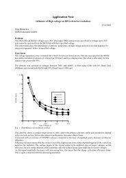
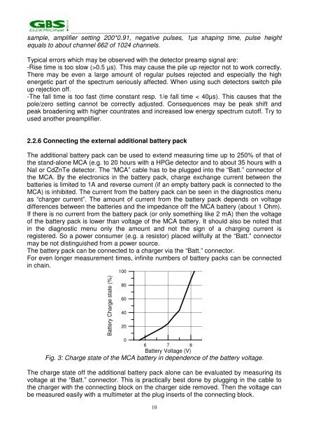
Battery Charge state (%)<br />
100<br />
80<br />
60<br />
40<br />
20<br />
0<br />
6 7 8<br />
Battery Voltage (V)<br />
Fig. 3: Charge state of the <strong>MCA</strong> battery in dependence of the battery voltage.<br />
The charge state off the additional battery pack alone can be evaluated by measuring its<br />
voltage at the “Batt.” connector. This is practically best done by plugging in the cable to<br />
the charger with the connecting block on the charger side removed. Then the voltage can<br />
be measured easily with a multimeter at the plug inserts of the connecting block.<br />
10