Service manual and spare parts list - BUKH Bremen
Service manual and spare parts list - BUKH Bremen
Service manual and spare parts list - BUKH Bremen

Create successful ePaper yourself
Turn your PDF publications into a flip-book with our unique Google optimized e-Paper software.
1.3 Gear Casing<br />
The oil-tight gearbox housing is made of<br />
a corrosion-resistant aluminium alloy<br />
chromized for added protection from corrosion.<br />
The gear casing is divided in a<br />
vertical plane into two equal halves.<br />
Cooling fins ensure good heat dissipation<br />
<strong>and</strong> mechanical rigidity.<br />
The oil filter screw with dipstick <strong>and</strong> the<br />
oil drain plug are screwed into the gear<br />
casing. The filler screw is provided with<br />
a breather hole.<br />
The actuating lever, actuating cam <strong>and</strong><br />
cover plate are a pre-assembled unit fitted<br />
laterally to the gearbox unit.<br />
Holes (see «Main dimensions» item 1.2<br />
pos. c) are provided for bolting the transmission<br />
to a flywheel housing or an<br />
adapter flange.<br />
1.4 Gear set<br />
The transmission is equipped with case<br />
hardened helical gears made of forged<br />
low-carbon alloy steel <strong>and</strong> case hardened<br />
spiral bevel gears (V drive). The<br />
drive shaft with the drive gears are an<br />
integral unit.<br />
The splined input shaft connecting the<br />
transmission with the engine is hardened<br />
as well.<br />
The driven shaft (propeller side) of the<br />
transmission, with the exception of the<br />
ZF15 MIV model, is fitted with an integrally<br />
forged coupling flange.<br />
The servo-automatic clutch system governs<br />
the direction of rotation of the input<br />
shaft, <strong>and</strong> ZF M transmission units are<br />
available for clockwise:<br />
(RH = right h<strong>and</strong>) or counterclockwise<br />
(LH = left h<strong>and</strong>) rotation.<br />
Manual <strong>and</strong> Spare Parts List ZF M line<br />
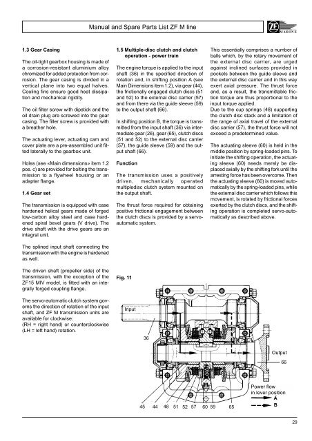
1.5 Multiple-disc clutch <strong>and</strong> clutch<br />
operation - power train<br />
The engine torque is applied to the input<br />
shaft (36) in the specified direction of<br />
rotation <strong>and</strong>, in shifting position A (see<br />
Main Dimensions item 1.2), via gear (44),<br />
the frictionally engaged clutch discs (51<br />
<strong>and</strong> 52) to the external disc carrier (57)<br />
<strong>and</strong> from there via the guide sleeve (59)<br />
to the output shaft (66).<br />
In shifting position B, the torque is transmitted<br />
from the input shaft (36) via intermediate<br />
gear (26), gear (65), clutch discs<br />
(51 <strong>and</strong> 52) to the external disc carrier<br />
(57), the guide sleeve (59) <strong>and</strong> the output<br />
shaft (66).<br />
Function<br />
The transmission uses a positively<br />
driven, mechanically operated<br />
multipledisc clutch system mounted on<br />
the output shaft.<br />
The thrust force required for obtaining<br />
positive frictional engagement between<br />
the clutch discs is provided by a servoautomatic<br />
system.<br />
Fig. 11<br />
Input<br />
36<br />
45 44 48 51 52 57 60 59 65<br />
This essentially comprises a number of<br />
balls which, by the rotary movement of<br />
the external disc carrier, are urged<br />
against inclined surfaces provided in<br />
pockets between the guide sleeve <strong>and</strong><br />
the external disc carrier <strong>and</strong> in this way<br />
exert axial pressure. The thrust force<br />
<strong>and</strong>, as a result, the transmittable friction<br />
torque are thus proportional to the<br />
input torque applied.<br />
Due to the cup springs (48) supporting<br />
the clutch disc stack <strong>and</strong> a limitation of<br />
the range of axial travel of the external<br />
disc carrier (57), the thrust force will not<br />
exceed a predetermined value.<br />
The actuating sleeve (60) is held in the<br />
middle position by spring-loaded pins. To<br />
initiate the shifting operation, the actuating<br />
sleeve (60) needs merely be displaced<br />
axially by the shifting fork until the<br />
arresting force has been overcome. Then<br />
the actuating sleeve (60) is moved automatically<br />
by the spring-loaded pins, while<br />
the external disc carrier which follows this<br />
movement, is rotated by frictional forces<br />
exerted by the clutch discs, <strong>and</strong> the shifting<br />
operation is completed servo-automatically<br />
as described above.<br />
Output<br />
66<br />
Power flow<br />
in lever position<br />
A<br />
B<br />
29