Service manual and spare parts list - BUKH Bremen
Service manual and spare parts list - BUKH Bremen
Service manual and spare parts list - BUKH Bremen

Create successful ePaper yourself
Turn your PDF publications into a flip-book with our unique Google optimized e-Paper software.
6.12 Final assembly of gearbox<br />
6.12.1 Place pre-assembled gearbox<br />
section (1) - (with intermediate gear) -<br />
on side wall.<br />
6.12.2 Place pre-assembled output shaft<br />
(66) in lower part of gearbox with flange<br />
side towards intermediate gear side (on<br />
ZF 15 MIV, bevel gear towards intermediate<br />
gear side).<br />
6.12.3 Place pre-assembled input shaft<br />
(36) in upper part of gearbox.<br />
6.12.4 (ZF 15 MIV only) Place pre-assembled<br />
quill shaft (73) in lower part of<br />
gearbox (watching to correct engagement<br />
of marked teeth).<br />
Add shims 78 on quill shaft:<br />
1.2 mm on side input shaft <strong>and</strong> 2.2 mm<br />
on side output flange.<br />
Add shims (70) on clutch shaft 2 x 0.1<br />
mm on side output flange.<br />
6.12.5 (ZF 15 MIV only) Check backlash<br />
0.08 to 0.13 mm (0.003 to 0.005 in). Between<br />
teeth of bevel gears using a dial<br />
indicator in contact with tooth surface.<br />
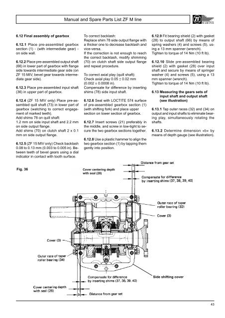
Fig. 36<br />
Manual <strong>and</strong> Spare Parts List ZF M line<br />
To correct backlash:<br />
Replace shim 78 side output flange with<br />
a thicker one to decrease backlash <strong>and</strong><br />
vice-versa.<br />
If the correction is not enough to reach<br />
the correct backlash, modify shimming<br />
(70) on clutch shaft side output flange<br />
<strong>and</strong> repeat procedure.<br />
To correct axial play (quill shaft):<br />
Check axial play 0.05 ± 0.02 mm<br />
(0.002 ± 0.0008 in).<br />
Compensate for difference by inserting<br />
shims (78) side input shaft.<br />
6.12.6 Seal with LOCTITE 574 surface<br />
of pre-assembled gearbox section (1)<br />
(with shifting fork) <strong>and</strong> place upper<br />
section on lower section of gearbox.<br />
6.12.7 Insert screws (21) preferably in<br />
the middle, <strong>and</strong> screw in low-tight to secure<br />
the two gearbox sections together.<br />
6.12.8 Use a plastic hammer to align the<br />
two gearbox section (1) by tapping them<br />
gently into position.<br />
Cover centering depth<br />
with seal (28)<br />
6.12.9 Fit bearing shield (2) with gasket<br />
(28) to output shaft (66) by means of<br />
spring washers (4) <strong>and</strong> screws (5), using<br />
a 13 mm spanner (wrench).<br />
Tighten to torque of 14 Nm (10 ft lb).<br />
6.12.10 Slide pre-assembled bearing<br />
shield (2) with gasket (28) over input<br />
shaft <strong>and</strong> secure by means of springer<br />
washer (4) <strong>and</strong> screws (5), using a 13<br />
mm spanner (wrench).<br />
Tighten to torque of 14 Nm (10 ft lb).<br />
6.13 Measuring the gears sets of<br />
input shaft <strong>and</strong> output shaft<br />
(see illustration)<br />
6.13.1 Tap outer races (32) <strong>and</strong> (34) on<br />
output <strong>and</strong> input shafts to eliminate bearing<br />
play, simultaneously rotating the<br />
shafts.<br />
6.13.2 Determine dimension «b» by<br />
means of depth gauge (see illustration).<br />
Side shifting cover<br />
43