"Civil Engineering" section of the FE Supplied-Reference Handbook ...
"Civil Engineering" section of the FE Supplied-Reference Handbook ...
"Civil Engineering" section of the FE Supplied-Reference Handbook ...

Create successful ePaper yourself
Turn your PDF publications into a flip-book with our unique Google optimized e-Paper software.
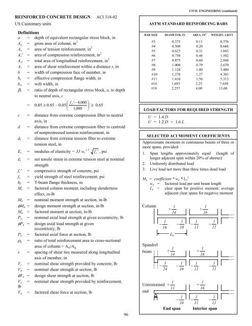
REINFORCED CONCRETE DESIGN ACI 318-02US Customary unitsDefinitionsa = depth <strong>of</strong> equivalent rectangular stress block, inA g = gross area <strong>of</strong> column, in 2A s = area <strong>of</strong> tension reinforcement, in 2A s ' = area <strong>of</strong> compression reinforcement, in 2A st = total area <strong>of</strong> longitudinal reinforcement, in 2A v = area <strong>of</strong> shear reinforcment within a distance s, inb = width <strong>of</strong> compression face <strong>of</strong> member, inb e = effective compression flange width, inb w = web width, inβ 1 = ratio <strong>of</strong> depth <strong>of</strong> rectangular stress block, a, to depthto neutral axis, cf c= ' − 4,000 0.85 ≥ 0.85 – 0.05 ≥ 0.65 1,000 c = distance from extreme compression fiber to neutralaxis, ind = distance from extreme compression fiber to centroid<strong>of</strong> nonprestressed tension reinforcement, ind t = distance from extreme tension fiber to extremetension steel, in1.5E c = modulus <strong>of</strong> elasticity = 33 w c f c ' , psiε t = net tensile strain in extreme tension steel at nominalstrengthf c ' = compressive strength <strong>of</strong> concrete, psif y = yield strength <strong>of</strong> steel reinforcement, psih f = T-beam flange thickness, inM c = factored column moment, including slendernesseffect, in-lbM n = nominal moment strength at <strong>section</strong>, in-lbφM n = design moment strength at <strong>section</strong>, in-lbM u = factored moment at <strong>section</strong>, in-lbP n = nominal axial load strength at given eccentricity, lbφP n = design axial load strength at giveneccentricity, lbP u = factored axial force at <strong>section</strong>, lbρ g = ratio <strong>of</strong> total reinforcement area to cross-<strong>section</strong>alarea <strong>of</strong> column = A st /A gs = spacing <strong>of</strong> shear ties measured along longitudinalaxis <strong>of</strong> member, inV c = nominal shear strength provided by concrete, lbV n = nominal shear strength at <strong>section</strong>, lbφV n = design shear strength at <strong>section</strong>, lbV s = nominal shear strength provided by reinforcement,lbV u = factored shear force at <strong>section</strong>, lbCIVIL ENGINEERING (continued)ASTM STANDARD REINFORCING BARSBAR SIZE DIAMETER, IN AREA, IN 2 WEIGHT, LB/FT#3 0.375 0.11 0.376#4 0.500 0.20 0.668#5 0.625 0.31 1.043#6 0.750 0.44 1.502#7 0.875 0.60 2.044#8 1.000 0.79 2.670#9 1.128 1.00 3.400#10 1.270 1.27 4.303#11 1.410 1.56 5.313#14 1.693 2.25 7.650#18 2.257 4.00 13.60LOAD FACTORS FOR REQUIRED STRENGTHU = 1.4 DU = 1.2 D + 1.6 LSELECTED ACI MOMENT COEFFICIENTSApproximate moments in continuous beams <strong>of</strong> three ormore spans, provided:1. Span lengths approximately equal (length <strong>of</strong>longer adjacent span within 20% <strong>of</strong> shorter)2. Uniformly distributed load3. Live load not more than three times dead load2M u = coefficient * w u * L nw u = factored load per unit beam lengthL n = clear span for positive moment; averageadjacent clear spans for negative momentColumnSpandrelbeam− 161− 241+ 141L n+ 1411Unrestrained + 11end− 101− 101− 101− 111− 111− 111+ 161+ 161+ 161− 111− 111− 11196End spanInterior span