"Civil Engineering" section of the FE Supplied-Reference Handbook ...
"Civil Engineering" section of the FE Supplied-Reference Handbook ...
"Civil Engineering" section of the FE Supplied-Reference Handbook ...

You also want an ePaper? Increase the reach of your titles
YUMPU automatically turns print PDFs into web optimized ePapers that Google loves.
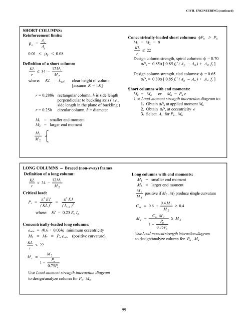
CIVIL ENGINEERING (continued)SHORT COLUMNS:Reinforcement limits:Astρg=Ag0.01 ≤ ρ g ≤ 0.08Definition <strong>of</strong> a short column:KL 12M1≤ 34 −rM 2where: KL = L col clear height <strong>of</strong> column[assume K = 1.0]r = 0.288h rectangular column, h is side lengthperpendicular to buckling axis ( i.e.,side length in <strong>the</strong> plane <strong>of</strong> buckling )r = 0.25h circular column, h = diameterM 1 = smaller end momentM 2 = larger end momentConcentrically-loaded short columns: φP n ≥ P uM 1 = M 2 = 0KL≤ 22rDesign column strength, spiral columns: φ = 0.70φP n = 0.85φ [ 0.85 f c ' ( A g − A st ) + A st f y ]Design column strength, tied columns: φ = 0.65φP n = 0.80φ [ 0.85 f c ' ( A g − A st ) + A st f y ]Short columns with end moments:M u = M 2 or M u = P u eUse Load-moment strength interaction diagram to:1. Obtain φP n at applied moment M u2. Obtain φP n at eccentricity e3. Select A s for P u , M uMM12LONG COLUMNS − Braced (non-sway) framesDefinition <strong>of</strong> a long column:KL 12M1> 34 −rM 2Critical load:2π EIP c =2( KL )π2E I=2( Lcol)where: EI = 0.25 E c I gConcentrically-loaded long columns:e min = (0.6 + 0.03h) minimum eccentricityM 1 = M 2 = P u e min (positive curvature)KL> 22rMcM 2=Pu1 −0.75PcUse Load-moment strength interaction diagramto design/analyze column for P u , M uLong columns with end moments:M 1 = smaller end momentM 2 = larger end momentM 1 positive if M1 , M 2 produce single curvatureMC m2=0.6+0.4 MM21≥0.4CmM 2M c =≥ M 2Pu1 −0.75PcUse Load-moment strength interaction diagramto design/analyze column for P u , M u99